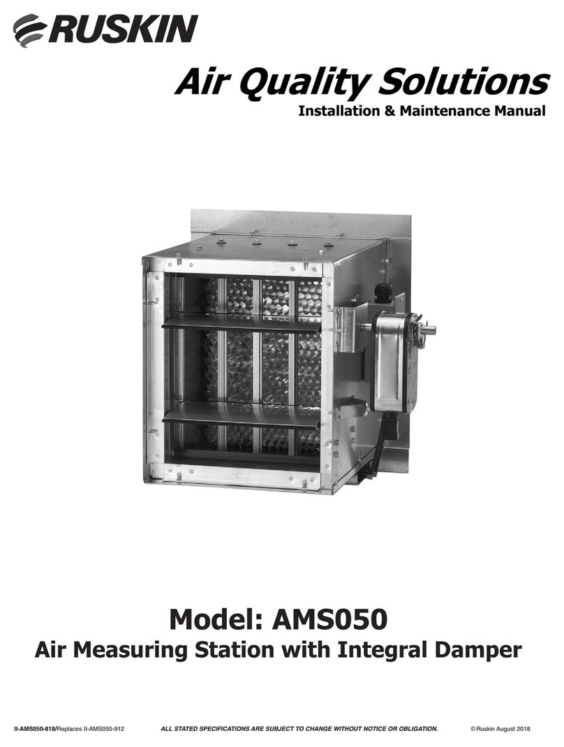
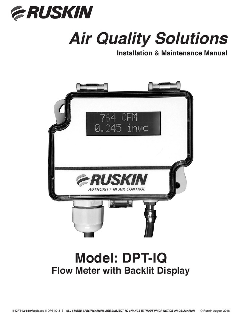
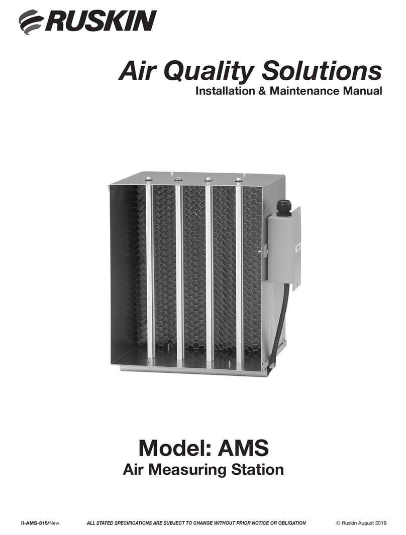
Ruskin AIRFLOW-IQ User manual

1
Airflow-IQ Start-up & Commissioning Guide
Air Quality Solutions
Start-up & Commissioning Guide
Model: AIRFLOW-IQ
Electronic Air Measuring Station with BACnet
Actuator and Class 1A Damper
ALL STATED SPECIFICATIONS ARE SUBJECT TO CHANGE WITHOUT PRIOR NOTICE OR OBLIGATION
II-AIRFLOW-IQ 718/Replaces II-AIRFLOW-IQ 418 ©Ruskin July 2018

2
Airflow-IQ Start-up & Commissioning Guide
AIRFLOW-IQ Electronic Air Measuring Station
with BACnet Actuator and Class 1A Damper
Table of Contents
Product Application ..................................................................3
General Information ..................................................................3
Electrical Guidelines ................................................................. 4
Receiving, Handling and Installation Guidelines ..............................................5
Construction Details ..................................................................6
Ideal Installations Air Measurement Station Placements ..................................... 7,8
Actuator Product Description ...........................................................9
BACnet Enabled Factory Supplied Controller ............................................. 9,10
Log on to Actuator ..................................................................11
WebServer Screenshots ..............................................................12
BACnet Object List ..................................................................13
Actuator Product Description ..........................................................14
BACnet Object Processing ............................................................15
TDP05K Wiring.................................................................16,17,18
Control Damper Information ...........................................................19
Menu Structure ................................................................. 20,21
Troubleshooting ....................................................................22
Maintenance ......................................................................23
Specifications......................................................................24
Warranty ..........................................................................

3
Airflow-IQ Start-up & Commissioning Guide
AIRFLOW-IQ Electronic Air Measuring Station
with BACnet Actuator and Class 1A Damper
Refer to the Ruskin.com website for the most up-to-date version of this document.
APPLICATIONS
Ruskin model AIRFLOW-IQ is a turn-key solution that combines the features of Ruskin’s TDP05K air flow and tem-
perature measuring probe(s) with Ruskin’s CD50 or CD60 control damper and Ruskin’s VAFB24-BAC RAMS Air Mea-
surement BACnet actuator/controller. The complete unit is factory assembled and calibrated to provide effective
setpoint air flow control from 0 to 5000 FPM (0 to 25 m/s) using analog or BACnet interface. The ultra low-leak,
class 1A rated CD50/CD60 damper meets leakage requirements of the International Energy Conservation Code.
This product is designed to be installed in almost any location that airflow needs to be measured. Measurements
may be improved by following the placement guidelines in this document. When adequate space is not available,
more probes and/or sensors are recommended.
Installation of the AIRFLOW-IQ Airflow Measuring Station placed directly downstream of heating coils, cooling coils,
or humidifiers is not recommended.
NORTH AMERICAN EMISSIONS COMPLIANCE
United States
This equipment has been tested and found to comply with the limits for a Class A digital device pursuant to Part
15 of the FCC Rules. These limits are designed to provide reasonable protection against harmful interference when
this equipment is operated in a commercial environment. This equipment generates, uses, and can radiate radio
frequency energy and, if not installed and used in accordance with the instruction manual, may cause harmful
interference to radio communications. Operation of this equipment in a residential area is likely to cause harmful
interference, in which case the user will be required to correct the interference at his/her own expense.
Canada
This Class (A) digital apparatus meets all the requirements of the Canadian Interference-Causing Equipment
Regulations.
Cet appareil numérique de la Classe (A) respecte toutes les exigences du Règlement sur le matériel brouilleur du
Canada.
All Airflow-IQ systems are supplied with a TDP05K Primary Display that is factory wired and may be connected
to up to 15 TDP05K Ancillary probe(s). The Primary Display is configured at the factory with customer supplied
parameters. For normal applications the Primary Display’s configuration should not need to be modified in the
field. However, if field configuration is necessary please reference the TDP05K Installation and Maintenance
Manual available at www.Ruskin.com, at this URL: http://www.ruskin.com/catalog/servefile/id/6766 or via this
QR Code:
APPLICATIONS
Ruskin model AIRFLOW-IQ is a turn-key solution that combines the features of Ruskin's TDP05K air flow and
temperature measuring probe(s) with Ruskin’s CD50 or CD60 control damper and Ruskin's VAFB24-BAC
RAMS Air Measurement BACnet actuator/controller. The complete unit is factory assembled and calibrated
to provide effective setpoint air flow control from 0 to 5000 FPM (0 to 25 m/s) using analog or BACnet
interface. The ultra low-leak, class 1A rated CD50/CD60 damper meets leakage requirements of the International
Energy Conservation Code.
This product is designed to be installed in almost any location that airflow needs to be measured.
Measurements may be improved by following the placement guidelines in this document. When adequate space is
not available, more probes and/or sensors are recommended.
Installation of the AIRFLOW-IQ Airflow Measuring Station placed directly downstream of heating coils, cooling
coils, or humidifiers is not recommended.
NORTH AMERICAN EMISSIONS COMPLIANCE
United States
This equipment has been tested and found to comply with the limits for a Class A digital device pursuant to Part
15 of the FCC Rules. These limits are designed to provide reasonable protection against harmful interference when
this equipment is operated in a commercial environment. This equipment generates, uses, and can radiate radio
frequency energy and, if not installed and used in accordance with the instruction manual, may cause harmful
interference to radio communications. Operation of this equipment in a residential area is likely to cause harmful
interference, in which case the user will be required to correct the interference at his/her own expense.
Canada
This Class (A) digital apparatus meets all the requirements of the Canadian Interference-Causing Equipment
Regulations.
Cet appareil numérique de la Classe (A) respecte toutes les exigences du Règlement sur le matériel brouilleur du
Canada.
AIRFLOW-IQ Electronic Air Measuring Station
with BACnet Actuator and Class 1A Damper
Refer to the Ruskin.com website for the most up-to-date version of this document.
2
All Airflow-IQ systems are supplied with a TDP05K Primary Display that is factory wired and may be connected to
up to 15 TDP05K Ancillary probe(s). The Primary Display is configured at the factory with customer supplied
parameters. For normal applications the Primary Display’s configuration should not need to be modified in the
field. However, if field configuration is necessary please reference the TDP05K Installation and Maintenance
Manual available at www.Ruskin.com, at this URL: http://www.ruskin.com/catalog/servefile/id/6766
or via this QR Code:
Airflow-IQ Start-up & Commissioning Guide
3

4
Airflow-IQ Start-up & Commissioning Guide
IMPORTANT: Only a qualified service technician should install this system. To avoid unsatisfactory operation
or damage to the product, strictly follow the instructions provided and do not substitute parts. Damage to the
product resulting from not following the instructions or using unauthorized parts may be excluded from the
manufacturer’s warranty coverage.
IMPORTANT: In addition to these instructions, the installation contractor shall comply with all local and
International codes and standards to ensure proper and safe installation.
Software Configuration Information for Commissioning:
After the installation described in this document is complete, please refer to the TDP05K Technical Bulletin for
information regarding configuration options.
The Technical Bulletin document can be viewed or downloaded at this location:
http://www.ruskin.com/catalog/servefile/id/6767.
The Technical Bulletin document can also be accessed via this QR Code:
Confirm power requirements before wiring actuator. Ruskin is not responsible for any damage to, or failure of
the unit caused by incorrect field wiring.
3
AD-1252 Thermal Dispersion Probe Airflow Measuring System Installation Instructions 1
preliminary - this information may change
Applications
The AD-1252 Thermal Dispersion Probe Airflow
Measuring System is an air-measurement device that
uses thermal dispersion technology to measure the
airflow velocity and temperature in duct and plenum
applications. Insertion probes are typically installed in
retrofit applications but may also be specified on new
construction projects.
The product may be used in rectangular, oval or round
applications when installed in accordance with this
installation manual. Use behind a rain hood, in front of
an outside air damper, return air duct, downstream of a
fan discharge or in the exhaust duct.
North American Emissions Compliance
United States
Canada
Installation
Mounting
The sensor density is based on extensive lab testing to
optimize the accuracy of the electronic controller.
When installing the thermal dispersion probe(s), use
the Square Duct Mounting and Round Duct Mounting
sections to determine the proper spacing between
each probe within the opening. Contact your local
Johnson Controls® representative if you have
questions regarding a particular application.
This equipment has been tested and found to
comply with the limits for a Class A digital device
pursuant to Part 15 of the FCC Rules. These limits
are designed to provide reasonable protection
against harmful interference when this equipment is
operated in a commercial environment. This
equipment generates, uses, and can radiate radio
frequency energy and, if not installed and used in
accordance with the instruction manual, may cause
harmful interference to radio communications.
Operation of this equipment in a residential area is
likely to cause harmful interference, in which case
the user will be required to correct the interference
at his/her own expense.
This Class (A) digital apparatus meets all the
requirements of the Canadian Interference-Causing
Equipment Regulations.
Cet appareil numérique de la Classe (A) respecte
toutes les exigences du Règlement sur le matériel
brouilleur du Canada.
ARNING: Risk of Electric Shock
nnect power supply before making
ectrical connections. Contact with
nents carrying hazardous voltage can
electrical shock and may result in
severe personal injury or death.
IMPORTANT: Only a qualified service technician
should install this system. To avoid unsatisfactory
operation or damage to the product, strictly follow
the instructions provided and do not substitute parts.
Damage to the product resulting from not following
the instructions or using unauthorized parts may be
excluded from the manufacturer’s warranty
coverage.
AD-1252 Thermal Dispersion Probe Airflow Measuring
System
Installation Instructions Part No. 44-1122-2, Rev. -
Issued June 30, 2009
Software Configuration Information for Commissioning:
After the installation described in this document is complete, please refer to the TDP05K Technical Bulletin
for information regarding conguration options.
The Technical Bulletin document can be viewed or downloaded at this location:
http://www.ruskin.com/catalog/servele/id/6767.
The Technical Bulletin document can also be accessed via this QR Code:
AD-1252 Thermal Dispersion Probe Airflow Measuring System Installation Instructions 1
preliminary - this information may change
Applications
The AD-1252 Thermal Dispersion Probe Airflow
Measuring System is an air-measurement device that
uses thermal dispersion technology to measure the
airflow velocity and temperature in duct and plenum
applications. Insertion probes are typically installed in
retrofit applications but may also be specified on new
construction projects.
The product may be used in rectangular, oval or round
applications when installed in accordance with this
installation manual. Use behind a rain hood, in front of
an outside air damper, return air duct, downstream of a
fan discharge or in the exhaust duct.
North American Emissions Compliance
United States
Canada
Installation
Mounting
The sensor density is based on extensive lab testing to
optimize the accuracy of the electronic controller.
When installing the thermal dispersion probe(s), use
the Square Duct Mounting and Round Duct Mounting
sections to determine the proper spacing between
each probe within the opening. Contact your local
Johnson Controls® representative if you have
questions regarding a particular application.
This equipment has been tested and found to
comply with the limits for a Class A digital device
pursuant to Part 15 of the FCC Rules. These limits
are designed to provide reasonable protection
against harmful interference when this equipment is
operated in a commercial environment. This
equipment generates, uses, and can radiate radio
frequency energy and, if not installed and used in
accordance with the instruction manual, may cause
harmful interference to radio communications.
Operation of this equipment in a residential area is
likely to cause harmful interference, in which case
the user will be required to correct the interference
at his/her own expense.
This Class (A) digital apparatus meets all the
requirements of the Canadian Interference-Causing
Equipment Regulations.
Cet appareil numérique de la Classe (A) respecte
toutes les exigences du Règlement sur le matériel
brouilleur du Canada.
WARNING: Risk of Electric Shock
Disconnect power supply before making
electrical connections. Contact with
components carrying hazardous voltage can
cause electrical shock and may result in
severe personal injury or death.
IMPORTANT: Only a qualified service technician
should install this system. To avoid unsatisfactory
operation or damage to the product, strictly follow
the instructions provided and do not substitute parts.
Damage to the product resulting from not following
the instructions or using unauthorized parts may be
excluded from the manufacturer’s warranty
coverage.
AD-1252 Thermal Dispersion Probe Airflow Measuring
System
Installation Instructions Part No. 44-1122-2, Rev. -
Issued June 30, 2009
MPORTANT: Only a qualied service technician Ishould install this system. To avoid unsatisfactory operation
or damage to the product, strictly follow the instructions provided and do not substitute parts. Damage to the
product resulting from not following the instructions or using unauthorized parts may be excluded from the
manufacturer’s warranty coverage.
Confirm power requirements before wiring actuator. Ruskin is not responsible for any damage to, or failure of
the unit caused by incorrect field wiring.
IMPORTANT: In addition to these instructions, the installation contractor shall comply with all local and Interna-
tional codes and standards to ensure proper and safe installation.
Airflow-IQ Start-up & Commissioning Guide
4
Risk of Electric Shock.
Disconnect the power supply before making electrical connections. Contact with components carrying hazardous
voltage can cause electric shock and may result in severe personal injury or death.
Risque de décharge électrique.
Débrancher l'alimentation avant de réaliser tout branchement électrique. Tout contact avec des composants
conducteurs de tensions dangereuses risque d'entraîner une décharge électrique et de provoquer des blessures
graves, voire mortelles.
Risk of Electric Shock.
Disconnect the power supply before making electrical connections. Contact with components carrying hazardous
voltage can cause electric shock and may result in severe personal injury or death.
Risque de décharge électrique.
Débrancher l’alimentation avant de réaliser tout branchement électrique. Tout contact avec des composants
conducteurs de tensions dangereuses risque d’entraîner une décharge électrique et de provoquer des blessures
graves, voire mortelles.

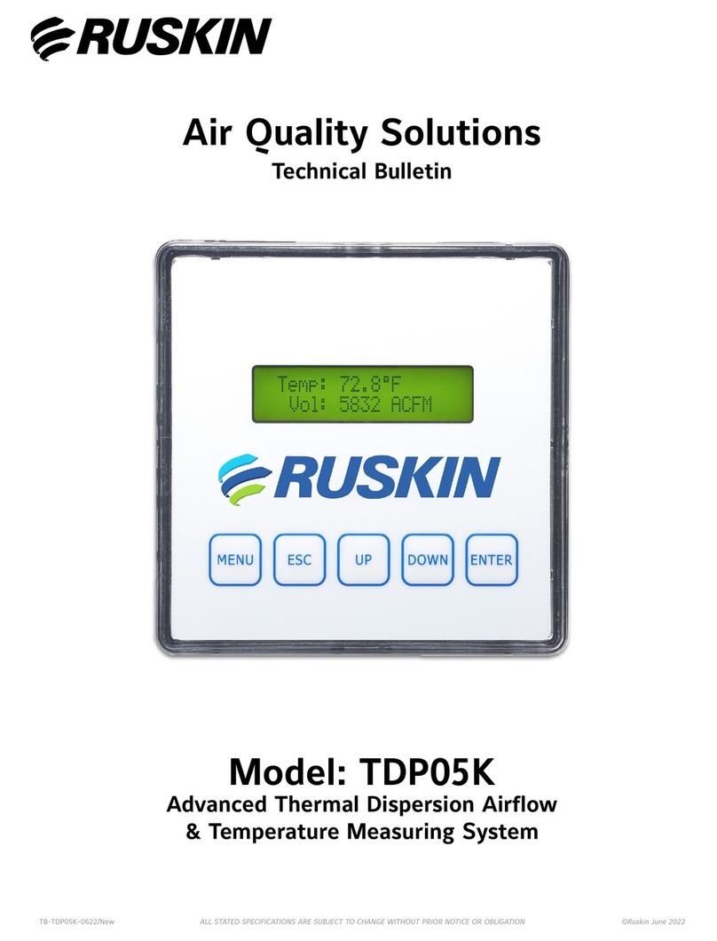
5
Airflow-IQ Start-up & Commissioning Guide
Unpacking and Installing the AIRFLOW-IQ Electronic Air Measuring Station
Remove the AIRFLOW-IQ from its shipping container and inspect for damage, rust or corrosion. Care must be taken
in handling the unit. Always handle the AIRFLOW-IQ by its frame. Do not lift it by the blade, linkage, axle, motor
or jackshaft. Do not drop, drag, step on or apply excessive bending, twisting or racking loads to the AIRFLOW-IQ.
Improper handling of the unit will have adverse affects on the calibration and could result in cancellation of the
warranty.
Inspect the ductwork and/or the opening where AIRFLOW-IQ will be installed for any obstructions or irregularities
that might interfere with the probes, blade, linkage rotation or the actuator. When installed in the ductwork, the
ductwork should be supported in the area of the AIRFLOW-IQ to prevent sagging.
The AIRFLOW-IQ must be installed with the frame square and without twisting or bending. Unless specifically
designed for a vertical blade application, the unit must be mounted with its blade axis in the horizontal plane.
The damper blades, axles and linkage must be able to operate without binding.
Ensure that the air enters the probes upstream and exits the damper downstream.
The best location for the extended shaft or jackshaft must be determined before installing the damper. After the
damper is installed the shaft location cannot be changed without removing the damper. The jackshaft, when pres-
ent, will always be in the leaving air stream. The AIRFLOW-IQ has a specific inlet and outlet and must be installed
in the correct orientation. The air enters through the air measurement probe(s) and exits the unit from the damper
frame side. Use appropriate shims between damper frame and duct opening to prevent distortion of the frame by
the fasteners holding the unit in place.
After installing the assembly in the ductwork or mounting hole, caulk around the damper frame to ensure that there
is no leakage or bypass air around the air measuring station.
The TDP05K probes are factory calibrated and tested in order to perform correctly in its job specific application.
Refer to the wiring schematic and controls section of this document for necessary field power connections.
Once electrical power is applied, the Primary display will go through a start-up sequence during which it will identify
and communicate with each airflow sensor. Once the start-up sequence has been complete, the Primary display will
show the measured airflow rate, velocity, and ambient air temperature.
Reasonable access must be provided to allow inspection and maintenance of the actuator, probes and damper.
The sensor density is based on extensive lab testing to optimize the accuracy of the AIRFLOW-IQ Electronic
Air Measuring Station. Contact your local Ruskin®representative if you have questions regarding a particular
application.

6
Airflow-IQ Start-up & Commissioning Guide
5
Duct
Height, in.
(mm)
Duct Width, in. (mm)
12
(305)
14
(356)
16
(406)
18
(457)
20
(508)
22
(559)
24
(610)
30
(762)
36
(914)
42
(1,067)
48
(1,219)
54
(1,372)
60
(1,524)
66
(1,676)
72
(1,829)
84
(2,134)
96
(2,438)
108
(2,743)
120
(3,048)
12 (305) 1/2 1/4 1/4 1/4 1/4 1/4 1/4 1/6 1/6 1/6 1/6 1/8 1/8 1/8 1/8 1/8 1/8 1/8 1/8
14 (356) 1/4 1/4 1/4 1/4 1/4 1/6 1/6 1/6 1/6 1/8 1/8 1/8 1/8 1/8 1/8 1/8 1/8 1/8 1/8
16 (406) 2/2 2/2 2/2 2/2 2/3 2/3 2/3 1/6 1/6 1/8 1/8 1/8 1/8 1/8 1/8 1/8 1/8 1/8 1/8
18 (457) 2/2 2/2 2/2 2/2 2/3 2/3 2/2 2/2 1/8 1/8 1/8 1/8 1/8 1/8 1/8 1/8 1/8 1/8 1/8
20 (508) 2/2 2/2 2/3 2/3 2/3 2/3 2/3 2/4 1/8 1/8 1/8 1/8 2/6 2/6 2/6 2/6 2/7 2/8 1/8
22 (559) 2/2 3/2 2/3 2/3 2/3 2/3 2/3 2/4 1/8 1/8 1/8 2/6 2/6 2/6 2/6 2/7 2/8 2/8 2/8
24 (610) 2/2 3/2 2/3 2/3 2/3 2/3 2/3 2/4 2/4 1/8 1/8 2/6 2/6 2/6 2/6 2/7 2/8 2/8 2/8
30 (762) 3/2 3/2 3/2 3/2 2/4 2/4 2/4 2/4 2/4 2/6 2/6 2/6 2/7 2/7 2/8 2/8 2/8 2/8 2/8
36 (914) 3/2 3/2 3/2 4/2 4/2 4/2 2/4 2/4 2/6 2/6 2/6 2/7 2/8 2/8 2/8 2/8 2/8 2/8 2/8
42 (1,067) 3/2 4/2 4/2 4/2 4/2 4/2 4/2 2/6 2/6 2/7 2/7 2/8 2/8 2/8 2/8 2/8 2/8 2/8 2/8
48 (1,219) 3/2 4/2 4/2 4/2 4/2 4/2 4/2 3/4 2/6 2/7 2/8 2/8 2/8 2/8 2/8 2/8 2/8 2/8 2/8
54 (1,372) 4/2 4/2 4/2 4/2 4/2 3/4 3/4 3/4 2/7 2/8 2/8 2/8 2/8 2/8 4/4 2/8 2/8 2/8 2/8
60 (1,524) 4/2 4/2 4/2 4/2 3/4 3/4 3/4 4/4 4/4 2/8 2/8 2/8 4/4 4/4 4/4 4/4 2/8 2/8 2/8
66 (1,676) 4/2 4/2 4/2 4/3 3/4 3/4 3/4 4/4 4/4 4/4 2/8 2/8 4/4 4/4 4/4 4/4 4/4 2/8 2/8
72 (1,829) 4/2 4/2 4/2 4/3 3/4 3/4 3/4 4/4 4/4 4/4 2/8 4/4 4/4 4/4 4/4 4/4 4/4 4/4 2/8
84 (2,134) 4/2 4/2 4/2 4/3 3/4 4/4 4/4 4/4 4/4 4/4 4/4 4/4 4/4 4/4 4/4 4/4 4/4 4/4 4/4
96 (2,438) 4/2 4/2 4/2 4/3 4/4 4/4 4/4 4/4 4/4 4/4 4/4 4/4 4/4 4/4 4/4 4/4 4/4 4/4 4/4
108 (2,743) 4/2 4/2 4/2 4/3 4/4 4/4 4/4 4/4 4/4 4/4 4/4 4/4 4/4 4/4 4/4 4/4 4/4 4/4 4/4
120 (3,048)4/2 4/2 4/2 4/3 4/4 4/4 4/4 4/4 4/4 4/4 4/4 4/4 4/4 4/4 4/4 4/4 4/4 4/4 4/4
1. The minimum diameter size is 12 x 6.5 inches (304 x 165 mm) for rectangular duct applications. Smaller sizes can be special
ordered. For sizes less than 12 x 6.5 inches (304 x 165 mm), use the same number of probes and sensors as the 12 x 12 in.
(304 x 304 mm) size.
TDP05K Advanced Thermal Dispersion Probe Airow Measuring System Installation Instructions
5
Table 1: Number of Probes/Sensors per Probe for Rectangular Duct Applications
1
Duct
Height, in.
(mm)
Duct Width, in. (mm)
12
(305)
14
(356)
16
(406)
18
(457)
20
(508)
22
(559)
24
(610)
30
(762)
36
(914)
42
(1,067)
48
(1,219)
54
(1,372)
60
(1,524)
66
(1,676)
72
(1,829)
84
(2,134)
96
(2,438)
108
(2,743)
120
(3,048)
12 (305) 1/2 1/4 1/4 1/4 1/4 1/4 1/4 1/6 1/6 1/6 1/6 1/8 1/8 1/8 1/8 1/8 1/8 1/8 1/8
14 (356) 1/4 1/4 1/4 1/4 1/4 1/6 1/6 1/6 1/6 1/8 1/8 1/8 1/8 1/8 1/8 1/8 1/8 1/8 1/8
16 (406) 2/2 2/2 2/2 2/2 2/3 2/3 2/3 1/6 1/6 1/8 1/8 1/8 1/8 1/8 1/8 1/8 1/8 1/8 1/8
18 (457) 2/2 2/2 2/2 2/2 2/3 2/3 2/2 2/2 1/8 1/8 1/8 1/8 1/8 1/8 1/8 1/8 1/8 1/8 1/8
20 (508) 2/2 2/2 2/3 2/3 2/3 2/3 2/3 2/4 1/8 1/8 1/8 1/8 2/6 2/6 2/6 2/6 2/7 2/8 1/8
22 (559) 2/2 3/2 2/3 2/3 2/3 2/3 2/3 2/4 1/8 1/8 1/8 2/6 2/6 2/6 2/6 2/7 2/8 2/8 2/8
24 (610) 2/2 3/2 2/3 2/3 2/3 2/3 2/3 2/4 2/4 1/8 1/8 2/6 2/6 2/6 2/6 2/7 2/8 2/8 2/8
30 (762) 3/2 3/2 3/2 3/2 2/4 2/4 2/4 2/4 2/4 2/6 2/6 2/6 2/7 2/7 2/8 2/8 2/8 2/8 2/8
36 (914) 3/2 3/2 3/2 4/2 4/2 4/2 2/4 2/4 2/6 2/6 2/6 2/7 2/8 2/8 2/8 2/8 2/8 2/8 2/8
42 (1,067) 3/2 4/2 4/2 4/2 4/2 4/2 4/2 2/6 2/6 2/7 2/7 2/8 2/8 2/8 2/8 2/8 2/8 2/8 2/8
48 (1,219) 3/2 4/2 4/2 4/2 4/2 4/2 4/2 3/4 2/6 2/7 2/8 2/8 2/8 2/8 2/8 2/8 2/8 2/8 2/8
54 (1,372) 4/2 4/2 4/2 4/2 4/2 3/4 3/4 3/4 2/7 2/8 2/8 2/8 2/8 2/8 4/4 2/8 2/8 2/8 2/8
60 (1,524) 4/2 4/2 4/2 4/2 3/4 3/4 3/4 4/4 4/4 2/8 2/8 2/8 4/4 4/4 4/4 4/4 2/8 2/8 2/8
66 (1,676) 4/2 4/2 4/2 4/3 3/4 3/4 3/4 4/4 4/4 4/4 2/8 2/8 4/4 4/4 4/4 4/4 4/4 2/8 2/8
72 (1,829) 4/2 4/2 4/2 4/3 3/4 3/4 3/4 4/4 4/4 4/4 2/8 4/4 4/4 4/4 4/4 4/4 4/4 4/4 2/8
84 (2,134) 4/2 4/2 4/2 4/3 3/4 4/4 4/4 4/4 4/4 4/4 4/4 4/4 4/4 4/4 4/4 4/4 4/4 4/4 4/4
96 (2,438) 4/2 4/2 4/2 4/3 4/4 4/4 4/4 4/4 4/4 4/4 4/4 4/4 4/4 4/4 4/4 4/4 4/4 4/4 4/4
108 (2,743) 4/2 4/2 4/2 4/3 4/4 4/4 4/4 4/4 4/4 4/4 4/4 4/4 4/4 4/4 4/4 4/4 4/4 4/4 4/4
120 (3,048)4/2 4/2 4/2 4/3 4/4 4/4 4/4 4/4 4/4 4/4 4/4 4/4 4/4 4/4 4/4 4/4 4/4 4/4 4/4
1. The minimum diameter size is 12 x 6.5 inches (304 x 165 mm) for rectangular duct applications. Smaller sizes can be special
ordered. For sizes less than 12 x 6.5 inches (304 x 165 mm), use the same number of probes and sensors as the 12 x 12 in.
(304 x 304 mm) size.
Table 1: Number of Probes/Sensors per Probe for Rectangular Duct Applications1
Duct
Height, in.
(mm)
Duct Width, in. (mm)
12
(305)
14
(356)
16
(406)
18
(457)
20
(508)
22
(559)
24
(610)
30
(762)
36
(914)
42
(1,067)
48
(1,219)
54
(1,372)
60
(1,524)
66
(1,676)
72
(1,829)
84
(2,134)
96
(2,438)
108
(2,743)
120
(3,048)
12 (305) 1/2 1/4 1/4 1/4 1/4 1/4 1/4 1/6 1/6 1/6 1/6 1/8 1/8 1/8 1/8 1/8 1/8 1/8 1/8
14 (356) 1/4 1/4 1/4 1/4 1/4 1/6 1/6 1/6 1/6 1/8 1/8 1/8 1/8 1/8 1/8 1/8 1/8 1/8 1/8
16 (406) 2/2 2/2 2/2 2/2 2/3 2/3 2/3 1/6 1/6 1/8 1/8 1/8 1/8 1/8 1/8 1/8 1/8 1/8 1/8
18 (457) 2/2 2/2 2/2 2/2 2/3 2/3 2/2 2/2 1/8 1/8 1/8 1/8 1/8 1/8 1/8 1/8 1/8 1/8 1/8
20 (508) 2/2 2/2 2/3 2/3 2/3 2/3 2/3 2/4 1/8 1/8 1/8 1/8 2/6 2/6 2/6 2/6 2/7 2/8 1/8
22 (559) 2/2 3/2 2/3 2/3 2/3 2/3 2/3 2/4 1/8 1/8 1/8 2/6 2/6 2/6 2/6 2/7 2/8 2/8 2/8
24 (610) 2/2 3/2 2/3 2/3 2/3 2/3 2/3 2/4 2/4 1/8 1/8 2/6 2/6 2/6 2/6 2/7 2/8 2/8 2/8
30 (762) 3/2 3/2 3/2 3/2 2/4 2/4 2/4 2/4 2/4 2/6 2/6 2/6 2/7 2/7 2/8 2/8 2/8 2/8 2/8
36 (914) 3/2 3/2 3/2 4/2 4/2 4/2 2/4 2/4 2/6 2/6 2/6 2/7 2/8 2/8 2/8 2/8 2/8 2/8 2/8
42 (1,067) 3/2 4/2 4/2 4/2 4/2 4/2 4/2 2/6 2/6 2/7 2/7 2/8 2/8 2/8 2/8 2/8 2/8 2/8 2/8
48 (1,219) 3/2 4/2 4/2 4/2 4/2 4/2 4/2 3/4 2/6 2/7 2/8 2/8 2/8 2/8 2/8 2/8 2/8 2/8 2/8
54 (1,372) 4/2 4/2 4/2 4/2 4/2 3/4 3/4 3/4 2/7 2/8 2/8 2/8 2/8 2/8 4/4 2/8 2/8 2/8 2/8
60 (1,524) 4/2 4/2 4/2 4/2 3/4 3/4 3/4 4/4 4/4 2/8 2/8 2/8 4/4 4/4 4/4 4/4 2/8 2/8 2/8
66 (1,676) 4/2 4/2 4/2 4/3 3/4 3/4 3/4 4/4 4/4 4/4 2/8 2/8 4/4 4/4 4/4 4/4 4/4 2/8 2/8
72 (1,829) 4/2 4/2 4/2 4/3 3/4 3/4 3/4 4/4 4/4 4/4 2/8 4/4 4/4 4/4 4/4 4/4 4/4 4/4 2/8
84 (2,134) 4/2 4/2 4/2 4/3 3/4 4/4 4/4 4/4 4/4 4/4 4/4 4/4 4/4 4/4 4/4 4/4 4/4 4/4 4/4
96 (2,438) 4/2 4/2 4/2 4/3 4/4 4/4 4/4 4/4 4/4 4/4 4/4 4/4 4/4 4/4 4/4 4/4 4/4 4/4 4/4
108 (2,743) 4/2 4/2 4/2 4/3 4/4 4/4 4/4 4/4 4/4 4/4 4/4 4/4 4/4 4/4 4/4 4/4 4/4 4/4 4/4
120 (3,048)4/2 4/2 4/2 4/3 4/4 4/4 4/4 4/4 4/4 4/4 4/4 4/4 4/4 4/4 4/4 4/4 4/4 4/4 4/4
1. The minimum diameter size is 12 x 6.5 inches (304 x 165 mm) for rectangular duct applications. Smaller sizes can be special
ordered. For sizes less than 12 x 6.5 inches (304 x 165 mm), use the same number of probes and sensors as the 12 x 12 in.
(304 x 304 mm) size.
HiGHEST SENSoR DENSiTY PER SqUARE FooT iN THE iNDUSTRY
12" 14" 16" 18" 20" 22" 24" 30" 36" 42" 48" 54" 60" 66" 72" 84" 96" 108" 120"
(305) (356) (406) (457) (508) (559) (610) (762) (914) (1067)(1219)(1372)(1524)(1676)(1829)(2134)(2438)(2743)
(3048)
12" (305)
1/2 1/4 1/4 1/4 1/4 1/4 1/4 1/6 1/6 1/6 1/6 1/8 1/8 1/8 1/8 1/8 1/8 1/8 1/8
14" (356)
1/4 1/4 1/4 1/4 1/4 1/6 1/6 1/6 1/6 1/8 1/8 1/8 1/8 1/8 1/8 1/8 1/8 1/8 1/8
16"(406)
2/2 2/2 2/2 2/2 2/3 2/3 2/3 1/6 1/6 1/8 1/8 1/8 1/8 1/8 1/8 1/8 1/8 1/8 1/8
18" (457)
2/2 2/2 2/2 2/3 2/3 2/3 2/3 1/6 1/8 1/8 1/8 1/8 1/8 1/8 1/8 1/8 1/8 1/8 1/8
20" (508)
2/2 2/2 2/3 2/3 2/3 2/3 2/3 2/4 1/8 1/8 1/8 1/8 2/6 2/6 2/6 2/6 2/7 2/8 1/8
22"(559)
2/2 3/2 2/3 2/3 2/3 2/3 2/3 2/4 1/8 1/8 1/8 2/6 2/6 2/6 2/6 2/7 2/8 2/8 2/8
24" (610)
2/2 3/2 2/3 2/3 2/3 2/3 2/3 2/4 2/4 1/8 1/8 2/6 2/6 2/6 2/6 2/7 2/8 2/8 2/8
30" (762)
3/2 3/2 3/2 3/2 2/4 2/4 2/4 2/4 2/4 2/6 2/6 2/6 2/7 2/7 2/8 2/8 2/8 2/8 2/8
36" (914)
3/2 3/2 3/2 4/2 4/2 4/2 2/4 2/4 2/6 2/6 2/6 2/7 2/8 2/8 2/8 2/8 2/8 2/8 2/8
42" (1067)
3/2 4/2 4/2 4/2 4/2 4/2 4/2 2/6 2/6 2/7 2/7 2/8 2/8 2/8 2/8 2/8 2/8 2/8 2/8
48" (1219)
3/2 4/2 4/2 4/2 4/2 4/2 4/2 3/4 2/6 2/7 2/8 2/8 2/8 2/8 2/8 2/8 2/8 2/8 2/8
54" (1372)
4/2 4/2 4/2 4/2 4/2 3/4 3/4 3/4 2/7 2/8 2/8 2/8 2/8 2/8 4/4 2/8 2/8 2/8 2/8
60" (1524)
4/2 4/2 4/2 4/2 3/4 3/4 3/4 4/4 4/4 2/8 2/8 2/8 4/4 4/4 4/4 4/4 2/8 2/8 2/8
66" (1676)
4/2 4/2 4/2 4/3 3/4 3/4 3/4 4/4 4/4 4/4 2/8 2/8 4/4 4/4 4/4 4/4 4/4 2/8 2/8
72" (1829)
4/2 4/2 4/2 4/3 3/4 3/4 3/4 4/4 4/4 4/4 2/8 4/4 4/4 4/4 4/4 4/4 4/4 4/4 2/8
84" (2134)
4/2 4/2 4/2 4/3 3/4 4/4 4/4 4/4 4/4 4/4 4/4 4/4 4/4 4/4 4/4 4/4 4/4 4/4 4/4
96" (2438)
4/2 4/2 4/2 4/3 4/4 4/4 4/4 4/4 4/4 4/4 4/4 4/4 4/4 4/4 4/4 4/4 4/4 4/4 4/4
108" (2743)
4/2 4/2 4/2 4/3 4/4 4/4 4/4 4/4 4/4 4/4 4/4 4/4 4/4 4/4 4/4 4/4 4/4 4/4 4/4
120" (3048)
4/2 4/2 4/2 4/3 4/4 4/4 4/4 4/4 4/4 4/4 4/4 4/4 4/4 4/4 4/4 4/4 4/4 4/4 4/4
Duct Height
"B"
Duct Width A - Probe Length
The model TDP05K probe assembly may be installed in square,
round, or oval ducts and plenums. Hardware required for the insertion
style mounting configuration (as depicted in the DETAILS shown
below) is provided as standard with the TDP05K. Stand-off mounting
hardware is available as an option for applications that require probes
mounted onto the upstream side of a Ruskin model CD50, CD60 or
insulated TED50 control damper (damper sold separately). For
specific installation and operation details, and for round or oval
applications, refer to the Installation and Maintenance Instructions.
The information on this data sheet is for general reference and is
subject to correction or modification.
DETAiL 3
DETAiL 2
DETAiL 4
Primary
Probe
Ancillary
Probe
Duct Height
Height / 2
Height / 4
Duct Height
Height / 2
Duct Width
Duct Width
Primary
Probe
Ancillary
Probe
Ancillary
Probe
Ancillary
Probe
Primary
Probe
Ancillary
Probe
Ancillary
Probe
Duct
Height
Height / 3
Height / 3
Height / 6
Duct
Height
Height / 4
Height / 4
Height / 4
Height / 8
Duct Width
Duct Width
DETAiL 1
Round Duct Mounting
Attach Round Duct Hinge Plate to Round Duct Mounting Plate.
Table 1: Number of Probes / Sensors per Probe for Rectangular Duct Applications
Rectangular Duct Width "A" = Probe Length
Airflow-IQ Start-up & Commissioning Guide
6
FACE VIEW
DAMPER SIDE
‘B’ DIM
‘A’ DIM
Figure 1

7
Airflow-IQ Start-up & Commissioning Guide
3D 1.5D 0.75D 0.75D
0.75D1.5D
1.5D
0.5D
≤15˚
≤15˚
≤15˚
≤15˚
0.5D 0.5D
1.5D
1D
2D
1D
UNVANED ELBOWS
DUCT AND PLENUM THERMAL DISPERSION PLACEMENT GUIDE
SWEEP ELBOWVANED ELBOWS
TRANSITIONS
FAN PLENUM SUPPLY CENTRIFUGAL FAN DISCHARGE
RETURN FAN PLENUM VANE AXIAL INTAKE
3D 1.5D
0.5D
1D
1.5D
0.5D
RETURN ‘T’ FITTINGSUPPLY ‘T’ FITTING
TDP05K ADVANCED THERMAL DISPERSION AIRFLOW
& TEMPERATURE MEASURING PROBE
PLACEMENT GUIDE
© Ruskin July 2017
NOTES:
Sensor uncertainty is +/-2% and does not include sampling uncertainty. The recommended number of probes and sensors, as shown in our installation manual, represent the minimum number of sensing
points that can be used for an installed accuracy of +/-3%, when locations meet suggested guidelines. Velocity sampling uncertainty can be reduced by adding more sensors, and when necessary more
probes, to help compensate for locations that do not have sufficient spacing between upstream and downstream obstructions.
D = Basic Equivalent Duct Diameter (Width + Height)
2
Minimum Mounting Distances
Figure 2 represents applications for which the TDP05K AirflowMeasuring System is most suitable. If your particular
application is not shown or if you do not have the space to observe the minimum distance, more probes and/or
sensing points are recommended; contact your local Ruskin representative for the best solution. The locations
shown on these details represent the minimum clearance from most obstruction that create an airflow disturbance.
Figure 2a: Minimum Mounting Distances
IMPORTANT: The probe enclosure cover is secured with three captive thumb screws. Take care when mount-
ing the probes to ensure there is adequate clearance to open the cover and make electrical connections.

8
Airflow-IQ Start-up & Commissioning Guide
Airflow-IQ Air Measurement Station Factory Supplied Actuator Controller
The actuator/controller is designed to modulate the Airflow-IQ damper to maintain a desired cfm setpoint.
Analog:
The air measurement is supplied from the TDP05K via a 0-10 VDC analog input to the actuator/controller (terminals
10 and 11 in the junction box).
BACnet:
The setpoint is established by the BACnetSetpoint datapoint. Table 1 lists all of the BACnet datapoints. The BACnet
Setpoint is a percentage of the MaxCFMSetpoint datapoint, which is set at the factory based on the default maxi-
mum velocity which is 5000 FPM, unless a different value was specified at the time the unit was ordered.
Flow Control Mode:
To operate the Airflow-IQ as a modulating damper, change the DamperMode BACnet data point (see Table 1) from
CurrentAirflow to DamperPosition.
Manual Override Close:
Damper manual override close can be accomplished with a zero volt setpoint or any value less than 2V. Damper will
also close on loss of signal on CFM setpoint terminal 12. Adding a switch in series with the 24 VAC or 0-10V signal
connected to terminal 12.
1256710 12
11
GROUND - BLACK
24V HOT- RED
MPBUS- ORANGE
C1 BACNET TCP - PINK
C2 BACNET TCP - GRAY
AIR FLOW SENSOR COM- YEL/BLK
AIR FLOW SENSOR 0-10V - YEL/PINK
CFM SETPOINT 0-10V YEL/GRAY
FIELD WIRING
POWER
GROUND - BLACK
24V HOT- RED
JUMPER 2 TO 12 FACTORY INSTALLED-RED
ACTUATOR VAFB24-BAC
+A01
-A01
24H
TDP05K
RED
WHITE
BLACK
24G
BLACK
OPTIONAL ANALOG
OUTPUT TO BAS
-
+
-
+
OPTIONAL BACnet
OUTPUT TO BAS
*500 Ohm resistor Factory Installed.
*
Remove jumper 2 to 12
when analog setpoint
input is connected.

9
Airflow-IQ Start-up & Commissioning Guide
Field power wiring:
use 18 ga wire, or
16 ga if over 25/

10
Airflow-IQ Start-up & Commissioning Guide
Ruskin Air Measurement Actuator (VAFB24-BAC) factory installed on TDP05K050/060
MODE OF OPERATION
The air measurement actuator is the BACNET interface and setup port for the air measurement station. The air
measurement actuator accepts an analog 0-10V signal via S2 input or a network driven CFM SETPOINT and will
modulate the damper based on measured CFM to get to desired air flow. Air flow measurement sensor is connect-
ed to Input 1 of the actuator and can represent velocity pressure or a velocity air flow measurement. Air measure-
ment is calculated based on actuator configuration and reported via the BACNET interface or analog output from the
air measurement sensor to the building automation system. Air Measurement actuator includes WEBSERVER and
can be configured using any web browser such as Internet Explorer. Analog input signal is required for stand-alone
air measurement control and monitoring when the network interface is not used. Direct Position Control is possible
via BACNET or Analog Input corresponding to Percent input.
FEATURES
Setup via integrated Web Server and Ethernet IP connection, directly to actuator.
BACNet MS/TP or IP
Fail Safe Signal Interlock T12, drives damper closed on loss of signal.
Spring open or spring close on loss of power as required for application.
Controls multiple Belimo MFT actuators – Use for Large multi-section air measurement stations or to control
return air damper or hot-deck cold-deck or face & bypass applications, equal or equal and opposite position.
COMMISSIONING
Site specific network interface configuration by installing contractor
Air Measurement Station configuration, size, sensor technology and settings by installing contractor to
match attached air measurement station.
WIRING
3-ft black plenum cable connector with the following pin assignments
Wire[1] Ground - Black
Wire[2] 24V Hot – Red
Wire[5] MPBus - Orange
Wire[7] COM_B – Grey
Wire[6] COM_A – Pink
Wire[10] Sensor Com – Yellow/Black
Wire[11] Sensor 1 – Yellow/Pink
Wire[12] Sensor 2 – Yellow/Grey
BUILT IN TRENDING
Short term 30 – day
Long Term Compressed file 6-Month

11
Airflow-IQ Start-up & Commissioning Guide
The laptop computer needs a fixed IP address in the same range as the actuator’s:
Lap Top IP Address: 192.168.0.7 for example would work.
(IP address cannot be the same as the actuator’s)
Subnet Mask: 255.255.255.0
Default gate way: 192.168.0.1
Configuring the air measurement actuator requires logging on to it with a laptop using Google Chrome.
Make sure the lap top’s WiFi is turned off to avoid a problem.
In the address bar at the top type the following IP address in Google Chrome;
Actuator’s IP address: 192.168.0.10:8080
Then click on the login button showing
User Name: admin
Password: rusnimda
This will bring up the configuration screen for the Air Measurement Actuator shown on page 12.

12
Airflow-IQ Start-up & Commissioning Guide
Ruskin VAFB24-BAC RAMS Actuator WEB Interface
RuskinVAFB24BACRAMSActuatorWEBInterface
Tuesday, January 2, 18
RuskinVAFB24BACRAMSActuatorWEBInterface
Tuesday, January 2, 18

13
Airflow-IQ Start-up & Commissioning Guide
Ruskin AMS Object List
AI – Analog Input
AO – Analog Output
AV – Analog Value
BI – Binary Input
BO – Binary Output
BV – Binary Value
MI – Multi-State Input
MO – Multi-State Output
MV – Multi-State Value
R – ReadOnly
W – Writable
C – Commandable (Contains Priority Array)
Example 1:
Example 2:
Example 3:
Name Description Type Inst Access Units Def Details
RuskinAMS Application Version AI 1 R no-units -
AirflowSetpoint Current Airflow Rate Setpoint AI 2 cfm -
Airflow Current Airflow Rate AI 3 R cfm -
AirVelocity Current Air Velocity AI 4 R fpm -
DamperPosition Damper Position Feedback AI 5 R pct -
DpReading Differential Pressure Sensor Value AI 6 R inches-water -
DamperArea Damper Area AV 1 W square-feet 4
MaxControlAirflow Maximum Controllable Airflow Rate AV 2 W cfm 5000
Ka Damper Ka Factor AV 3 W no-units 2400
Factor1/m Damper 1/m Factor AV 4 W no-units 0.5
BACnetSetpoint BACnet Control Setpoint AO 1 C percent 0
EnableStatus Damper Enabled Status (Safety) BI 1 R percent -
off=alarm
on=normal
DamperMode Damper Mode V 1 W no-units 1
1=Flow;
2=Position;

14
Airflow-IQ Start-up & Commissioning Guide
Actuator Product Description:
Product Description:
The device is an air damper control actuator with the added benefit of a built-in programmable controller. Free pro-
gramming environment allows handling of a wide range of HVAC control applications. MP-Bus master capabilities
allow this device to monitor and control up to 15 additional slave devices that contain Ruskin MP-Bus technology,
affording significant expandability. BACnet server functionality allows easy integration in standard building auto-
mation systems. The commissioning of the device (BACnet Device Address, IP Address settings, MS/TP Address …)
is done via the integrated web-server.
BACnet Standard Device Profile: BACnet Application Specific Controller (B-ASC)
BACnet Interoperability Building Blocks supported:
Data Sharing - ReadProperty-B (DS-RP-B)
Data Sharing - ReadPropertyMultiple-B (DS-RPM-B)
Data Sharing - WriteProperty-B (DS-WP-B)
Device Management - DynamicDeviceBinding-B (DM-DDB-B)
Device Management - DynamicObjectBinding-B (DM-DOB-B)
Device Management - DeviceCommunicationControl-B (DM-DCC-B)
Segmentation Capability: No
Data Link Layer Options: BACnet IP, (Annex J)
BACnet IP, (Annex J), Foreign Device
MS/TP master,
baud rates: 9’600, 19’200, 38’400, 76’800, 115’200
Device Address Binding: No static device binding supported
Networking Options: None
Character Sets Supported: ANSI X3.4

15
Airflow-IQ Start-up & Commissioning Guide
Object Processing
1) Only if object is commandable
2) Only if MS/TP is the selected data link layer type
• The properties Object_Name and Location of the Device Object support up to 255 characters
(all other character strings are read-only).
• The device does not support the CreateObject and DeleteObject service.
• The device supports DeviceCommunicationControl service. No password is required.
Object Type Optional Properties Writeable Properties
Analog Input Description
Analog Output Description Present_Value
Analog Value Description Present_Value
Binary Input Description
Active_Text
Inactive_Text
Binary Output Description Present_Value
Active_Text
Inactive_Text
Relinquish_Default
1)
Priority_Array
1)
Binary Value Description Present_Value
Active_Text
Inactive_Text
Relinquish_Default
1)
Priority_Array
1)
Device Description Object_Identifier
Location Object_Name
APDU_Timeout
Number_Of_APDU_Retries
Max_Master 2)
Max_Info_Frames 2)
Multistate Input Description
State_Text
Multistate Value Description Present_Value
State_Text
Relinquish_Default
1)
Priority_Array
1)
Multistate Output Description Present_Value
State_Text
Relinquish_Default
1)
Priority_Array
1)
Service Processing

16
Airflow-IQ Start-up & Commissioning Guide
Wiring
Cable Specifications
NOTES:
All Airflow-IQ Stations are supplied with a Ruskin TDP05K primary probe that is factory wired to one or more
TDP05K air measurement probe(s). The primary probe was configured at the factory with customer supplied
parameters. For normal applications the configuration stored in the primary probe should not need to be changed in
the field. However, if field configuration isrequired please refer to the TDP05K Tech Manual available on Ruskin.com.
Note:
Wires in an exposed or conduit installation must meet the wiring minimum bend radius of 3.5 in. (89 mm).
IMPORTANT: Do not run the probe wiring in the same conduit as AC power wiring or with wiring used to supply
highly inductive loads, such as motors, contactors, and relays. Fluctuating, erratic, and inaccurate signal levels
are possible when AC power wiring is present in the same conduit as the signal lines. Run the wiring away from
variable frequency drives and broadcast antennas, variable frequency drives and broadcast antennas.
IMPORTANT: For ease of installation, a composite four-wire cable similar to Connect-Air part number
W24182P-2306BL with communications and power in one cable is recommended. Alternatively, use a twisted
shielded pair 24 AWG low capacitance wire communications cable and an 18 AWG power cable, which should be
run in a separate conduit.

17
Airflow-IQ Start-up & Commissioning Guide
Primary Probe Wiring
Figure 15: Primary Probe Wiring
Analog Output
1. Carefully remove the top of the Phoenix Contact®screw terminal connector and insert the wires. Tighten the
terminals and reconnect them to the controller board.
2. Connect the 4 to 20 mA analog flow output (A01: Pos and Com) and the 4 to 20 mAanalog output factory default
temperature (A02: temperature output) from the primary probe to a building automation system.
Note: The factory default flow output is A01. Either output A01 or A02 can be configured for temperature or flow,
or both can be configured for temperature and flow.
Probe Network
Connect the Shield, D+,and D- from the primary to the ancillary probe or remote display using the approved
communications wire. A03 is not used at this time.
Note: The two D- and D+ connections are electrically identical.
BACnet®Output
1. Carefully remove the top of the Phoenix Contact®screw terminal connector and insert the wires. Tighten the
terminals and reconnect them to the controller board.
2. Connect the BACnet® output (A- and B+) from the primary probe to a BACnet network.
Note: The two A- connections and the two B+ connections are electrically identical.
3.
Connect the shield wire from the primary probe to the Shield terminal. The shield only connects on the output end.
Note: The Shield is connected on one end of each wire run and should never be connected on both ends of one wire.
IMPORTANT: The primary probe provides two 4 to 20 mA signals to building automation systems. Do not apply
loop power to this probe. The system requires a two-wire power connection and separate two-wire connections
for each analog output. Analog signal outputs are isolated from power.
preliminary—this information may change
TDP05K Advanced Thermal Dispersion Probe Airflow Measuring System Installation Instructions
12
Ruskin—CONFIDENTIAL
Wiring Connections
Primary Probe Wiring
Analog Output
1. Carefully remove the top of the Phoenix Contact® screw terminal connector and insert the wires. Tighten the
terminals and reconnect them to the controller board.
2. Connect the 4 to 20 mA analog flow output (A01: Pos and Com) and the 4 to 20 mA analog output factory
default temperature (A02: temperature output) from the primary probe to a building automation system.
Note: The factory default flow output is A01. Either output A01 or A02 can be configured for temperature or flow,
or both can be configured for temperature and flow.
Probe Network
Connect the Shield, D+, and D- from the primary to the ancillary probe or remote display using the approved
communications wire.
BACnet® Output
1. Carefully remove the top of the Phoenix Contact screw terminal connector and insert the wires. Tighten the
terminals and reconnect them to the controller board.
2. Connect the BACnet® output (A- and B+) from the primary probe to a BACnet network.
IMPORTANT: Do not run the probe wiring in the same conduit as AC power wiring or with wiring used to supply
highly inductive loads, such as motors, contactors, and relays. Fluctuating, erratic, and inaccurate signal levels
are possible when AC power wiring is present in the same conduit as the signal lines. Run the wiring away from
variable frequency drives and broadcast antennas.
IMPORTANT: The primary probe provides two 4 to 20 mA signals to building automation systems. Do not apply
loop power to this probe. The system requires a two-wire power connection and separate two-wire connections
for each analog output. Analog signal outputs are isolated from power.
Figure 15: Primary Probe Wiring
1
Table 5: Primary Probe Features
Callout Feature Description
1 Reset Cycles power to the device without unplugging it
preliminary—this information may change
TDP05K Advanced Thermal Dispersion Probe Airflow Measuring System Installation Instructions
12
Ruskin—CONFIDENTIAL
Wiring Connections
Primary Probe Wiring
BACnet® Output
1. Carefully remove the top of the Phoenix Contact screw terminal connector and insert the wires. Tighten the
terminals and reconnect them to the controller board.
2. Connect the BACnet® output (A- and B+) from the primary probe to a BACnet network.
IMPORTANT: Do not run the probe wiring in the same conduit as AC power wiring or with wiring used to supply
highly inductive loads, such as motors, contactors, and relays. Fluctuating, erratic, and inaccurate signal levels
are possible when AC power wiring is present in the same conduit as the signal lines. Run the wiring away from
variable frequency drives and broadcast antennas.
IMPORTANT: The primary probe provides two 4 to 20 mA signals to building automation systems. Do not apply
loop power to this probe. The system requires a two-wire power connection and separate two-wire connections
for each analog output. Analog signal outputs are isolated from power.
Figure 15: Primary Probe Wiring
Note: The two A- connections and the two B+ connections are electrically identical.”
preliminary—this information may change
TDP05K Advanced Thermal Dispersion Probe Airflow Measuring System Installation Instructions
12
Ruskin—CONFIDENTIAL
Wiring Connections
Primary Probe Wiring
Analog Output
1. Carefully remove the top of the Phoenix Contact® screw terminal connector and insert the wires. Tighten the
terminals and reconnect them to the controller board.
2. Connect the 4 to 20 mA analog flow output (A01: Pos and Com) and the 4 to 20 mA analog output factory
default temperature (A02: temperature output) from the primary probe to a building automation system.
Note: The factory default flow output is A01. Either output A01 or A02 can be configured for temperature or flow,
or both can be configured for temperature and flow.
Probe Network
Connect the Shield, D+, and D- from the primary to the ancillary probe or remote display using the approved
communications wire.
1. Carefully remove the top of the Phoenix Contact screw terminal connector and insert the wires. Tighten the
terminals and reconnect them to the controller board.
2. Connect the BACnet® output (A- and B+) from the primary probe to a BACnet network.
IMPORTANT: Do not run the probe wiring in the same conduit as AC power wiring or with wiring used to supply
highly inductive loads, such as motors, contactors, and relays. Fluctuating, erratic, and inaccurate signal levels
are possible when AC power wiring is present in the same conduit as the signal lines. Run the wiring away from
variable frequency drives and broadcast antennas.
IMPORTANT: The primary probe provides two 4 to 20 mA signals to building automation systems. Do not apply
loop power to this probe. The system requires a two-wire power connection and separate two-wire connections
for each analog output. Analog signal outputs are isolated from power.
Figure 15: Primary Probe Wiring
Airflow-IQ Start-up & Commissioning Guide
16
Analog Output
1. Carefully remove the top of the Phoenix Contact® screw terminal connector and insert the wires. Tighten the
terminals and reconnect them to the controller board.
2. Connect the 4 to 20 mA analog flow output (A01: Pos and Com) and the 4 to 20 mA analog output factory
default temperature (A02: temperature output) from the primary probe to a building automation system.
Note: The factory default flow output is A01. Either output A01 or A02 can be configured for temperature or flow,
or both can be configured for temperature and flow.
Probe Network
Connect the Shield, D+, and D- from the primary to the ancillary probe or remote display using the approved
communications wire. A03 is not used at this time.
Note: The two D- and D+ connections are electrically identical.
BACnet® Output
Table 5: Primary Probe Features
Callout Feature Description
1 Reset Cycles power to the device without unplugging it

18
Airflow-IQ Start-up & Commissioning Guide
Power
1. Carefully remove the top of the Phoenix Contact®screw terminal connector and insert the wires. Tighten the
terminals and reconnect them to the controller board.
2. Connect the 24 VAC power wires to the primary probe using 15 VA power (recommended).
3. Connect the 24 VAC hot wire to the primary probe terminal labeled 24H.
4. Connect the 24 VAC common wire to the primary probe terminal labeled 24G.
Note: The two 24H connections are electrically identical, and the two 24G connections are also electrically identical.
Completing the Wiring
When the primary and ancillary probes, remote display and network wiring are complete, apply power to the system.
The version number is displayed followed by the number of probes found and total sensors. Confirm this informa-
tion is correct for the air measurement system installed. If it is incorrect, check all probe network wiring and probe
address dial settings.
Confirm that no two ancillary probes are set for the same address. Each probe address must be unique on the probe
network to work correctly. The primary probe and remote display are hard-coded addresses and do not need to be
changed or addressed. Confirm the connections are made to the probe network are not to the BACnet or analog
output connections on the primary probe. After the device warms up, the temperature and flow readings display.
Refer to the TDP05K Advanced Thermal Dispersion Probe Air Flow Measuring System Technical Bulletin
http://www.ruskin.com/catalog/servefile/id/6767 for detailed configuration instructions.
TDP05K Advanced Thermal Dispersion Probe Airflow Measuring System Installation Instructions
13
Ruskin—CONFIDENTIAL
preliminary —this information may change
3. Connect the shield wirefrom the primary probe to the Sh terminal. The shield only connects on the output end.
Note: The Shield is connected on one end of each wire run and should never be connected on both ends of one wire.
Power
1. Carefully remove the top of the Phoenix Contact screw terminal connector and insert the wires. Tighten the
terminals and reconnect them to the controller board.
2. Connect the 24 VAC power wires to the primary probe using 15 VA power (recommended).
3. Connect the 24 VAC hot wire to the primary probe terminal labeled 24H.
4. Connect the 24 VAC common wire to the primary probe terminal labeled 24G.
Note: The two 24H connections are electrically identical, and the two 24G connections are also electrically identical.
Ancillary Probe Wiring
Network
1. Carefully remove the top of the Phoenix Contact screw terminal connector and insert the wires. Tighten the
terminals and reconnect them to the controller board.
2. Connect the probe network terminal from the primary probe to the probe network in terminal on the ancillary
probe(s).
a. Connect the shield wire from the primary probe to the Sh Out terminal. The shield only connects on one
end.
b. Connect the 24 AWG black wire from the primary probe terminal labeled Network D- to the ancillary probe
terminal labeled Probe Network D-.
c. Connect the 24 AWG white wire from the primary probe terminal labeled Network D+ to the ancillary probe
terminal labeled Probe Network D+.
3. Connect additional probes in a daisy-chain series.
Note: The last probe in each air measurement station must have the end of line (EOL) switch set for the probe
network (switch 3[seeFigure 16]). If the primary probe output is connected to a BACnet network interface and
the TDP05K Airflow Measuring System is the end of line in the BACnetnetwork, set the BACnet switch to 1 ON
(shown in the off position in Figure 16).
TDP05K Advanced Thermal Dispersion Probe Airflow Measuring System Installation Instructions
13
Ruskin—CONFIDENTIAL
preliminary —this information may change
3. Connect the shield wirefrom the primary probe to the Sh terminal. The shield only connects on the output end.
Note: The Shield is connected on one end of each wire run and should never be connected on both ends of one wire.
Power
1. Carefully remove the top of the Phoenix Contact screw terminal connector and insert the wires. Tighten the
terminals and reconnect them to the controller board.
2. Connect the 24 VAC power wires to the primary probe using 15 VA power (recommended).
3. Connect the 24 VAC hot wire to the primary probe terminal labeled 24H.
4. Connect the 24 VAC common wire to the primary probe terminal labeled 24G.
Note: The two 24H connections are electrically identical, and the two 24G connections are also electrically identical.
Ancillary Probe Wiring
Note: The last probe in each air measurement station must have the end of line (EOL) switch set for the probe
network (switch 3[seeFigure 16]). If the primary probe output is connected to a BACnet network interface and
the TDP05K Airflow Measuring System is the end of line in the BACnetnetwork, set the BACnet switch to 1 ON
(shown in the off position in Figure 16).
Figure 16: Ancillary Probe Wiring
TDP05K Advanced Thermal Dispersion Probe Airflow Measuring System Installation Instructions
13
Ruskin—CONFIDENTIAL
preliminary —this information may change
Power
1. Carefully remove the top of the Phoenix Contact screw terminal connector and insert the wires. Tighten the
terminals and reconnect them to the controller board.
2. Connect the 24 VAC power wires to the primary probe using 15 VA power (recommended).
3. Connect the 24 VAC hot wire to the primary probe terminal labeled 24H.
4. Connect the 24 VAC common wire to the primary probe terminal labeled 24G.
Note: The two 24H connections are electrically identical, and the two 24G connections are also electrically identical.
Network
1. Carefully remove the top of the Phoenix Contact screw terminal connector and insert the wires. Tighten the
terminals and reconnect them to the controller board.
2. Connect the probe network terminal from the primary probe to the probe network in terminal on the ancillary
probe(s).
a. Connect the shield wire from the primary probe to the Sh Out terminal. The shield only connects on one
end.
b. Connect the 24 AWG black wire from the primary probe terminal labeled Network D- to the ancillary probe
terminal labeled Probe Network D-.
c. Connect the 24 AWG white wire from the primary probe terminal labeled Network D+ to the ancillary probe
terminal labeled Probe Network D+.
3. Connect additional probes in a daisy-chain series.
Note: The last probe in each air measurement station must have the end of line (EOL) switch set for the probe
network (switch 3[seeFigure 16]). If the primary probe output is connected to a BACnet network interface and
the TDP05K Airflow Measuring System is the end of line in the BACnetnetwork, set the BACnet switch to 1 ON
(shown in the off position in Figure 16).
Figure 16: Ancillary Probe Wiring
TDP05K Advanced Thermal Dispersion Probe Airflow Measuring System Installation Instructions
13
Ruskin—CONFIDENTIAL
preliminary —this information may change
3. Connect the shield wirefrom the primary probe to the Sh terminal. The shield only connects on the output end.
Note: The Shield is connected on one end of each wire run and should never be connected on both ends of one wire.
Power
1. Carefully remove the top of the Phoenix Contact screw terminal connector and insert the wires. Tighten the
terminals and reconnect them to the controller board.
2. Connect the 24 VAC power wires to the primary probe using 15 VA power (recommended).
3. Connect the 24 VAC hot wire to the primary probe terminal labeled 24H.
4. Connect the 24 VAC common wire to the primary probe terminal labeled 24G.
Note: The two 24H connections are electrically identical, and the two 24G connections are also electrically identical.
Ancillary Probe Wiring
Network
1. Carefully remove the top of the Phoenix Contact screw terminal connector and insert the wires. Tighten the
terminals and reconnect them to the controller board.
2. Connect the probe network terminal from the primary probe to the probe network in terminal on the ancillary
probe(s).
a. Connect the shield wire from the primary probe to the Sh Out terminal. The shield only connects on one
end.
b. Connect the 24 AWG black wire from the primary probe terminal labeled Network D- to the ancillary probe
terminal labeled Probe Network D-.
c. Connect the 24 AWG white wire from the primary probe terminal labeled Network D+ to the ancillary probe
terminal labeled Probe Network D+.
3. Connect additional probes in a daisy-chain series.
Figure 16: Ancillary Probe Wiring
TDP05K Advanced Thermal Dispersion Probe Airflow Measuring System Installation Instructions
13
Ruskin—CONFIDENTIAL
preliminary —this information may change
3. Connect the shield wirefrom the primary probe to the Sh terminal. The shield only connects on the output end.
Note: The Shield is connected on one end of each wire run and should never be connected on both ends of one wire.
Power
1. Carefully remove the top of the Phoenix Contact screw terminal connector and insert the wires. Tighten the
terminals and reconnect them to the controller board.
2. Connect the 24 VAC power wires to the primary probe using 15 VA power (recommended).
3. Connect the 24 VAC hot wire to the primary probe terminal labeled 24H.
4. Connect the 24 VAC common wire to the primary probe terminal labeled 24G.
Note: The two 24H connections are electrically identical, and the two 24G connections are also electrically identical.
Ancillary Probe Wiring
Network
1. Carefully remove the top of the Phoenix Contact screw terminal connector and insert the wires. Tighten the
terminals and reconnect them to the controller board.
2. Connect the probe network terminal from the primary probe to the probe network in terminal on the ancillary
probe(s).
a. Connect the shield wire from the primary probe to the Sh Out terminal. The shield only connects on one
end.
Note: The last probe in each air measurement station must have the end of line (EOL) switch set for the probe
network (switch 3[seeFigure 16]). If the primary probe output is connected to a BACnet network interface and
the TDP05K Airflow Measuring System is the end of line in the BACnetnetwork, set the BACnet switch to 1 ON
(shown in the off position in Figure 16).
Figure 16: Ancillary Probe Wiring
When the primary and ancillary probes, remote display and network wiring are complete, apply power to the
system. The version number is displayed followed by the number of probes found and total sensors. Confirm
this information is correct for the air measurement system installed. If it is incorrect, check all probe network wiring
and probe address dial settings.
Confirm that no two ancillary probes are set for the same address. Each probe address must be unique on the
probe network to work correctly. The primary probe and remote display are hard-coded addresses and do not
need to be changed or addressed. Confirm the connections are made to the probe network are not to the
BACnet or analog output connections on the primary probe. After the device warms up, the temperature and
flow readings display.
Refer to the TDP05K Advanced Thermal Dispersion Probe Air Flow Measuring System Technical Bulletin
http://www.ruskin.com/catalog/servefile/id/6767 for detailed configuration instructions.
Completing the Wiring
RecRecRectaRectaRectangRectangRectangRectangularRectangularRectangularRectangularRectangularRectangular
Rectangulartangungunguularularular ct Wct Wct Wct Widthct Widthct Widthct Widthct Widthidth "A" = P"A" = Prob
"A" = Prob"A" = Prob"A" = Prob"A" = Probrobe Lengthe Lengthe Lengthe Lengthe Lengthgth
Table 1: Number ofProbes/Sensors per Probe for Rectangular Duct AAppplications
DuDuDuDuDuDuDuDuDuDuDuct HeightDuct Height
"B""B" 8"
(203)
12"
(305)
14"
(356)
16"
(406)
18"
(457)
20"
(508)
22"
(559)
24"
(610)
30"
(762)
36"
(914)
42"
(1067)
48"
(1219)
54"
(1372) (1524)
6
(1676)
60" 6" 72"
(1829)
84"
(2134)
96"
(2438)
108"
(2743)
120"
(3048)
8" (203) 1/2 1/2 1/4 1/4 1/4 1/4 1/4 1/4 1/6 1/6 1/6 1/6 1/8 1/8 1/8 1/8 1/8 1/8 1/8 1/8
12" (305) 1/2 1/2 1/4 1/4 1/4 1/4 1/4 1/4 1/6 1/6 1/6 1/6 1/8 1/8 1/8 1/8 1/8 1/8 1/8 1/8
14" (356) 1/2 1/4 1/4 1/4 1/4 1/4 1/6 1/6 1/6 1/6 1/8 1/8 1/8 1/8 1/8 1/8 1/8 1/8 1/8 1/8
16" (406) 2/2 2/2 2/2 2/2 2/2 2/3 2/3 2/3 1/6 1/6 1/8 1/8 1/8 1/8 1/8 1/8 1/8 1/8 1/8 1/8
18" (457) 2/2 2/2 2/2 2/2 2/3 2/3 2/3 2/3 1/6 1/8 1/8 1/8 1/8 1/8 1/8 1/8 1/8 1/8 1/8 1/8
20" (508) 2/2 2/2 2/2 2/3 2/3 2/3 2/3 2/3 2/4 1/8 1/8 1/8 1/8 2/6 2/6 2/6 2/6 2/7 2/8 2/8
2/2 3/222" (559) 2/2 2/3 2/3 2/3 2/3 2/3 2/4 1/8 1/8 1/8 2/6 2/6 2/6 2/6 2/7 2/8 2/8 2/8
24" (610) 2/2 2/2 3/2 2/3 2/3 2/3 2/3 2/3 2/4 2/4 1/8 1/8 2/6 2/6 2/6 2/6 2/7 2/8 2/8 2/8
30" (762) 3/2 3/2 3/2 3/2 3/2 2/4 2/4 2/4 2/4 2/4 2/6 2/6 2/6 2/7 2/7 2/8 2/8 2/8 2/8 2/8
" (106
" (914
42
3/2 3/2 3/2 3/236 ) 4/2 4/2 4/2 2/4 2/4 2/6 2/6 2/6 2/7 2/8 2/8 2/8 2/8 2/8 2/8 2/8
7) 3/2 3/2 4/2 4/2 4/2 4/2 4/2 4/2 2/6 2/6 2/7 2/7 2/8 2/8 2/8 2/8 2/8 2/8 2/8 2/8
48" (1219) 3/2 3/2 4/2 4/2 4/2 4/2 4/2 4/2 3/4 2/6 2/7 2/8 2/8 2/8 2/8 2/8 2/8 2/8 2/8 2/8
554" (1372 4/2 4/2 4/2 4/2 4/2 4/2 3/4 3/4 3/4 2/7 2/8 2/8 2/8 2/8 2/8 4/4 2/8 2/8 2/8 2/8
660" (1524 4/2 4/2 4/2 4/2 4/2 3/4 3/4 3/4 4/4 4/4 2/8 2/8 2/8 4/4 4/4 4/4 4/4 2/8 2/8 2/8
666" (1676 4/2 4/2 4/2 4/2 4/3 3/4 3/4 3/4 4/4 4/4 4/4 2/8 2/8 4/4 4/4 4/4 4/4 4/4 2/8 2/8
772" (1829 4/2 4/2 4/2 4/2 4/3 3/4 3/4 3/4 4/4 4/4 4/4 2/8 4/4 4/4 4/4 4/4 4/4 4/4 4/4 2/8
884" (2134 4/2 4/2 4/2 4/2 4/3 3/4 4/4 4/4 4/4 4/4 4/4 4/4 4/4 4/4 4/4 4/4 4/4 4/4 4/4 4/4
10
9
8
4/24/2 4/2 4/2 4/3 4/4 4/4 4/4 44/ 4/4 4/4 4/4 4/4 4/4 4/4 4/4 4/4 4/4 4/4 4/46" (2438)
" (2743) 4/2 4/2 4/2 4/2 4/3 4/4 4/4 4/4 4/4 4/4 4/4 4/4 4/4 4/4 4/4 4/4 4/4 4/4 4/4 4/4
120" (3048) 4/2 4/2 4/2 4/2 4/3 4/4 4/4 4/4 4/4 4/4 4/4 4/4 4/4 4/4 4/4 4/4 4/4 4/4 4/4 4/4
Airflow-IQ Start-up & Commissioning Guide
17
3. Connect the shield wire from the primary probe to the Shield terminal. The shield only connects on the output end.
Note: The Shield is connected on one end of each wire run and should never be connected on both ends of one wire.
Table 1: Number of Probes/Sensors per Probe for Rectangular Duct Applications

19
Airflow-IQ Start-up & Commissioning Guide
COMMERCIAL CONTROL DAMPER OPERATION & MAINTENANCE
Regular maintenance is essential to ensure that a building’s air control system will perform as intended under
normal conditions. Regular maintenance should include periodic testing of all equipment associated with the air
control system such as initiating devices, fans, dampers, controls, etc. Ruskin recommends each damper be cy-
cled and tested every 6 months and in accordance with local codes and actuator manufacture recommendations
(if damper has actuator). If dampers are installed in potentially dirty airstreams, the blades and other internal parts
may need annual cleaning to avoid dirt build up.
MAINTENANCE
• Remove any foreign material.
• Verify that hardware used to install damper does not contact moving parts of the damper.
• Lubricate linkage, bearings and other moveable parts with a silicone lubricant. Do not use petroleum-base
products as they could cause excessive dust collection.
• Operate (open and close) the damper via the actuator or extended shaft.
• Check the blade linkage to make sure the blade shafts and blades rotate 90° from full open to full closed.
• Consult Ruskin if problems are encountered.
OPERATION
• Operate damper through full cycle, verify that all blades open and close completely. Check for loose linkage from
actuator (if used) through jackshafting (if multi-section) and damper side linkage. Tighten linkage as required.

20
Airflow-IQ Start-up & Commissioning Guide
Menu Structure of TDP05K
Refer to the TDP05K Advanced Thermal Dispersion Probe Airflow Measuring System Technical Bulletin
http://www.ruskin.com/catalog/servefile/id/6767 for detailed configuration instructions.
Main Display (Normal Operation)
Line 1 displays the average temperature and line 2 displays the average velocity or volume.
Menu Button Selections
• Operator Menu
• Supervisor Menu
TDP05K Operator Menu
The Operator Menu allows the user to view and change system parameters and variables.
Table 8: Operator Menu Options (Part 1 of 2)
Operator Menu Submenus Submenu Function Submenu Selections
(Actual Display Name)
Enable Operator PIN Enables PIN protection for the Operator Menu N/A
(Enable Oper PIN)
Change Operator PIN Allows the user to update the PIN N/A
(Change Oper PIN)
Flow Configuration Allows system variable configuration Duct Shape
(Flow Config) Duct Width
Duct Height
Duct Diameter
Duct Area
Site Elevation
Relative Humidity
Flow Units
Output Lockout
Display Configuration Select parameters for displayed data Display Filter
(Display Config) Display Units
Display Flow Type
Line 2 Parameters
Line 2 Custom
Analog Output 1 Parameters Select Analog Output 1 parameters (flow, Analog Output 1 Parameters
(Output 1 Param) temperature, or none)
Analog Output 2 Parameters Select Analog Output 2 parameters (flow, Analog Output 2 Parameters
(Output 2 Param) temperature, or none)
Temperature Low Pass Filter Selects amount of filtering applied to the analog Temperature Low Pass Filter
(Temp LPF) output for temperature
Flow Low Pass Filter Selects amount of filtering applied to the analog Flow Low Pass Filter
(Flow LPF) output for flow
Analog Output Calibration Spans the analog outputs for temperature and flow. Output 1 mA Offset
(Output Cal Menu) Use the positive or negative offset if 4 mA output is Output 1MA Low Span
not as expected. Output 1 mA High Span
Output 2 mA Offset
Output 2 mA Low Span
Output 2 mA High Span
Design Range Low
Design Range High
Temperature Range Low
Temperature Range High
Table of contents
Other Ruskin Measuring Instrument manuals

Ruskin
Ruskin TDFi-RT Service manual

Ruskin
Ruskin AMS Instruction Manual

Ruskin
Ruskin EFAMS Instruction Manual

Ruskin
Ruskin AMS810 User manual

Ruskin
Ruskin TDP05K Service manual

Ruskin
Ruskin RRS ROOFTOP User manual

Ruskin
Ruskin DPT-IQ Instruction Manual

Ruskin
Ruskin AMS050 Instruction Manual

Ruskin
Ruskin TDP05K Instruction Manual

Ruskin
Ruskin EFAMS Manual