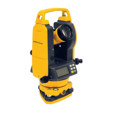
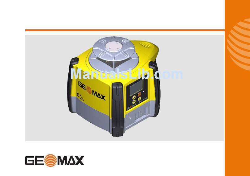
CST/BERGER CST202 User manual

CST202
CST205
INSTRUCTION MANUAL
Electronic
Total Station

CST/Berger Electronic Total Station
User’s Guide
Thank you for selecting the CST/Berger Electronic Total Station. For
the best performance of the instrument, please read this operator’s
manual carefully and keep it in a convenient location for future
reference. Some of the diagrams shown in this manual may be
simplified for easier understanding.
Specifications and alterations to the product or manual may occur at
any time without notification to user. Please contact CST/Berger for
updated information regarding your new Total Station.
Please make sure to complete the included Warranty Information
Certificate. Please send back to CST/Berger at the following
address:
Warranty Information Center
CST/Berger – Service Department
255 W. Fleming Street
Watseka, IL 60970
(800) 435-1859 Toll Free
(800) 913-0049 Toll Free Fax

CONTENTS
READ THIS FIRST
1.PRECAUTIONS FOR SAFE OPERATION 1
2.PRECAUTIONS 3
3.NOMENCLATURE AND FUNCTION 5
3.1 Parts of the instrument 5
3.2 Mode diagram-default set up 6
4.BASIC OPERATION 7
4.1 Basic key operation 7
4.2 Display functions 9
4.3 Display symbol 9
PREPARATION BEFORE MEASUREMENT
5.USING THE BATTERY 10
5.1 Charging procedure 10
5.2 Cautions 10
5.3 Charger operation manual 10
5.4 Installing battery 11
5.5 Removing battery 11
5.6 Battery power display 11
6.SETTING UP THE INSTRUMENT 12
7.FOCUSSING AND TARGET SIGHTING 13
8.POWER ON 14
9.FUNCTION IN THE STAR KEY(*) MODE 15
9.1 Tilt angle display and compensation 15
9.2 Checking the memory quickly 16
BASIC MEASUREMENT
10.ANGEL MEASUREMENT 17
10.1 Measuring the horizontal angle between two points 18
10.2 Setting the horizontal angle to a required value 18
10.3 Selecting the direction of horizontal angle (HAL/HAR) 20
10.4 %Slope 21
10.5 Horizontal angle repetition 22
10.6 Outputting angle measurement data 23
11.DISTANCE MEASREMENT 24
11.1 EDM Settings 24
11.2 Returned signal checking 27
11.3 Distance and angle measurement 27
11.4 Outputting distance measurement data 28
12.COORDINATE MEASUREMENT 29
12.1 Inputting instrument station coordinate 30
12.1.1Inputting instrument station coordinate from
keyboard 30
12.1.2Reading in registered coordinate data 31
12.2 Azimuth angle setting 32

12.3 Inputting the height of instrument and target 33
12.4 3-D coordinate measurement 34
ADVANCED MEASUREMENT
13.SETTING-OUT MEASUREMENT 36
13.1 Distance setting-out measurement 36
13.2 Coordinates setting-out measurement 40
14.OFFSET MEASUREMENT 45
14.1 Distance offset measurement 45
14.2 Angle offset measurement 47
15.MISSING LINE MEASUREMENT 50
15.1 Measuring the distance between 2 or more points 50
15.2 Changing the starting point 52
16 REM MEASUREMENT 54
17.RESECTION MEASUREMENT 56
17.1 Calculating the station coordinate by measuring 2 known points 57
17.2 Calculating the station coordinate using multiple known
points
59
18.AREA CALCULATION 61
19.SETTING-OUT LINE 63
19.1 Defining baseline 63
19.2 Setting-out line point 65
19.3 Setting-out line 67
RECORDING AND MANAGING THE DATA
20.THE OPERATION IN THE MEMORY MODE 69
20.1 Managing the job file 69
20.1.1 Reviewing and deleting record in job file 70
20.1.2 Changing name of a job 71
20.1.3 Deleting a job 72
20.1.4 Outputting job data to computer 73
20.2 Inputting coordinate data of known point 74
20.2.1 Inputtin
g
coordinate data of known point from the
keyboard 74
20.2.2 Inputtin
g
coordinate data of known point from an
external equipment 75
20.3 Reviewing and deleting known point data 76
20.4 Deleting all the known point data 77
20.5 Inputting codes 78
20.6 Reviewing and deleting codes 79
20.7 Displaying the status of memory 80
20.8 Initializing the memory 80
21.RECORDING DATA IN THE RECORD MODE 81
21.1 Recording distance measurement data 81
21.2 Recording angle measurement data 83
21.3 Recording coordinate measurement data 85
OPERATION IN THE CONFIG MODE
22.CHANGING THE PARAMETER SETTINGS 87

22.1Observation condition 87
22.2Instrument configuration 89
22.3Allocating key function 90
22.3.1 Defining softkeys 90
22.3.2 Registering a softkeys allocation 92
22.3.3 Recalling a softkeys allocation 93
22.4Unit setting 94
ADJUSTMENT
23.SETTING THE INSTRUMENT CONSTANT 95
23.1Tilt zero point error check and adjustment 95
23.1.1 Checking tilt zero point error 95
23.1.2 Tilt zero point error adjustment 95
23.2Vertical circle index error and collimation error correction 97
23.3Setting additive constant and multiple constant of distance 99
24.CHECKS AND ADJUSTMENTS 101
24.1Plate level and circular level 101
24.2Reticle 102
24.3Adjusting the telescope axis 103
24.4Optical plummet 104
OTHER INFORMATION
25.BI-DIRECTIONAL COMMUNICATION 105
26.MAINTENANCE 107
27.ERROR MESSAGES 107
28.TOTAL STATION SPECIFICATION CHART 110

1
1. PRECAUTIONS FOR SAFE OPERATION
General Warnings
zUsing the instrument near areas that contain high levels of dust, ash,
combustible materials or in poorly ventilated areas may result in damage due
to explosions.
zDo not attempt to service or repair instrument without proper training. Fire,
shock or severe burns might occur due to disassembly or improper assembly.
zAt no time should you look through the telescope at the sun or high intensity
lighting. Severe eye damage may result up to and including loss of sight.
Additionally, do not look at reflected light from prisms, mirrors or any
reflective device as this too could result in severe eye dama
g
e or loss of si
g
ht.
Contact your distributor to secure Optional Solar Filters for solar
observations.
zDo not use the carrying case as a seat or stool as it may become unstable or
slippery due to wet weather or improper balance. Severe injuries may
result.
zImproper use of accessories such as the plumb-bob or service tools may
result in personal injury. Take proper care with all accessories included.
zEnsure that the handle is properly attached to the instrument and that the
locking knobs are securely fastened. Failure to do so may result in damage
to the instrument should it fall off while being transported by handle. This
may also result in personal injury. Please take same care with the attached
Tribrach. Ensure that it is also securely fastened or the same result may
occur.

2
Power supply
zDo not use voltage other than the specified power supply voltage.
Additionally do not use damaged power cords, plugs or loose outlets. Fire or
electrical shock could result.
zDo not use third party cords or chargers as fire or instrument damage may
occur.
zTake care in keeping batteries and chargers clear of obstructions or covering
while in use. Sparks could be induced, leading to fire.
zUse only the specified battery charger to recharge batteries.
zDo not store or dispose of batteries near fire. An explosion may occur.
zTo prevent shorting of the battery in storage, apply insulating tape or
equivalent to the terminals. Otherwise shorting could occur resulting in fire or
burns.
zIf battery or charger become wet, do not use. Do not touch power products
with wet hands. Fire, shock or short may result causing serious burns or
loss of life.
zShould any liquid leak from battery, avoid contact. Improper handling may
cause serious injury.
Tripod
zWhen mounting or setting the instrument to the tripod, tighten the centering
screw securely to the instrument. Failure to tighten the bell housing properly
could result in the instrument falling off the tripod, causing severe damage to
the instrument or severe personal injury.
zEnsure that the tripod legs are securely tightened and planted firmly into the
ground. Failure to tighten the screws or quick clamps could result in the
tripod collapsing, causing instrument damage or personal injury.
zTake extra care when planting tripod legs into the ground so as not to stab
the feet of nearby persons. Severe personal injury may occur.
zWhen moving instrument, DO NOT shoulder the tripod with the Total Station
still attached. The instrument may snap off causing damage to the
instrument or personal injury.
zWhen transporting the tripod, ensure that all locks or clamps are securely
tightened and that any tripod straps are engaged. Failure to do so may
result in personal injury if the tripod opens and hits someone.

3
2.PRECAUTIONS
Precautions concerning water and dust resistance
zDo not put the instrument in the water. The instrument conforms to IPX4, so
the normal rain can not damage to the instrument, but improper use near
water can severely damage the instrument resulting in costly repairs.
zEnsure that the battery is properly mounted and locked in the instrument.
This will aid in the reduction of moisture or dust collecting in the battery
compartment.
zMake sure that the inside of the carrying case and the instrument are dry
before closing the case. If moisture is trapped inside the case, it may cause
damage to the instrument resulting in costly repairs. If the instrument does
get wet, dry off the instrument and place in the case only for transport.
Upon arriving back at home or office remove instrument from case and allow
both case and instrument to air dry overnight.
zNever place the instrument directly on the ground. Doing so may result in
sand, dust or debris finding its way into the instrument causing substantial
damage or costly repairs.
Using
zIt is best to mount a total station on a wood, fiberglass, composite or similar
tripod. Mounting instrument on Aluminum Tripods may result in inaccurate
readings do to the general properties of metals and expansion and
contraction.
zEnsure that the tribrach is in proper working order and that the locking
mechanism is working properly. This will reduce the chance of the
instrument coming loose on the tribrach and providing erroneous readings.
zPlease make sure that all configuration and parameter settings are set
properly prior to making measurements or recording data.
zAlways turn the instrument power off before removing the battery. Failure
may result in a power spike damaging the instrument.

4
Other Precautions
zAllow the instrument to adjust to the ambient temperature of the work site
prior to taking measurements. Temperature variations may cause subtle
changes in the instrument such as fogging of the lenses. This is normal as
long as the fogging takes place on the outside lens. Should the instrument
fog on the inside, please take the instrument to your nearest service center
for adjustment and service.
zThe CST/Berger Total Station is a precision instrument. Care must be taken
when using this instrument. Please avoid shock or jolts to the instrument as
they may negatively affect the calibration of the instrument. Please contact
your dealer or CST/Berger Service Facility should you need to have the
instrument calibrated.

3.NOMENCLATURE AND FUNCTION
3.1 Parts of the instrument
5
Tripod clamp
Vertical clamp an
d
fine motion screw
Telescope
focusing knob
Base plate
Display
Plate level
Telescope eyepiece
and focus
Horizontal clamp
and fine motion
screw
Battery
Handle
securing screw
Leveling foot screw
Tripod
Data input /outpu
t
connector
Operation panel
Optical plummet
Sighting collimator
Objective lens
Handle

3.2 Mode diagram-default set up. Record mode
6
Measmode
REC/Dist. data
H
ZA 99°43′13″
HAR 120°09′12″
ALL MODE OFS MEAS
MEAS
H
ZA 99°43′13″
HAR 120°09′12″ P1
DIST SHV HSET EDM
0SET CRD S-O REC
MLM RESE MENU HT
MENU
1. Coordinate
2. S-O
3. Resection
4. MLM
5. REM
6. Area calc.
7. Offset
8. Repetition
9. S-O line
Status screen
Memory mode Config. mode
Please note that function keys on the display may be different due to the
possibility of the keypad being configured with a custom layout.
TOTAL STATION
Ver 3.5
NO. 000001
MEAS MEM CNFG
MEMORY
1. Job
2. Known data
3. Code
4. Memory status
5. Init. memory
CONFIG
1. Obs.condition
2. Instr.config
3. Key function
4. Unit
Menu mode
【CNFG】
【ESC】
【ESC】【MENU】
【REC】
【MEAS】
【MEM】 【ESC】

4.BASIC OPERATION
4.1 Basic key operation
1.Power Key
Power on :press 【】。
Power off :press 【】, hold on 2 second.
2.Function key
【F1】~【F4】: Select the function of matching the soft keys.
【ESC】:Cancel the input data or return to the previous screen.
【SFT】:Switch between upper and lower case.
【BS】: Delete a character on the left.
【PAGE】:Toggle between the display pages.
【】:Select the item/ Accept input value /Accept the option.
3.Keyboard shortcuts
【SFT】+【*】:Press【SFT】, and then press【*】,enter the star key mode.
【SFT】+【一】:Press【SFT】,and then press【一】, enter the EDM signal checking.
4. Cursor key
:Left, right, up and down cursor or select other option
5.Alphanumeric key
【0】~【9】: During numeric input, input number of the key. During alphabetic
input, input the characters displayed above the key in the order
they are listed.
【.】:Input a decimal point.
【-】:Input minus sign.
7

Example 1:Input file name “FTS”
(1) Press【SFT】to come in the inputting letters mode, there will be
the letter “a” displayed on the right of the screen.
(2) Press 【2】three times, and then input the “F”。
(3) Press【】to move the curser to the right, press 【7】twice
and input the letter “T”.
(4) Press 【】to move the curser to the right, press 【7】once
and input the letter “S”.
(5) Press 【】to confirm it.
Selectajob
a
JOB:FTS
LIST
Example 2:Set the unit of air pressure as “mmHg”:
(1) In the config. mode , Press 【】/【】to move the cursor
to “4.Unit”. Press【 】to confirm it.
(2) Press 【】/【】to move the cursor to “Pres. unit”
(3) Press 【】/【】to move the cursor and select the unit
“mmHg”.
(4) Press【】to confirm it and then exit.
CONFIG
1.Obs. condition
2.Instr. const
3.Key function
4.Unit
Ang. unit *deg
Dist. unit *m
Temp. unit *℃
Press. unit mmHg
8

4.2 Display functions
Status screen
9
Total Station
Ver 3.5
NO. 000001
Meas mode screen
4.3 Display symbol
In the Meas mode , the symbol meaning:
zPC prismconstantvalue
zppm atmospheric correction factor
zS slope distance
zH horizontal distance
zV height distance
zZA zenithangle
zVA verticalangle
zHAR horizontal angle right
zHAL horizontal angle left
zHAh hold on the horizontal angle
MEAS MEM CNFG
MEAS
H a
ZA 99°43′13″
HAR 120°09′12″ P1
DIST SHV HSET EDM
Battery power
Keys status
Compensation
Page number
Instrument series
Software version
Instrument No.
Distance
Vertical angle
Horizontal angle

10
5.USING THE BATTERY
This instrument has the charger and battery of itself. The voltage of the battery is 7.2V.
Please charge it before measurement. Please read the operation manual carefully
before you use it.
5.1 Charging procedure
(1) Connect the battery to the charger.
(2) Plug the charger into the wall outlet. Make sure the battery contacts the
charger well. When charging starts, the red lamp starts blinking.
(3) The light turns to green when charging is finished.
(4) When charging finished, unplug the charger and then remove the battery.
5.2 Cautions
(1) Do not remove the battery while the instrument is ON.
(2) Before removing the battery, turn off the power of the instrument.
(3) When installing/removing the battery, make sure that moisture or dust
particles do not come in contact with the inside of the instrument.
(4) Periodically clean the contacts with the cleaning cloth to keep them free of dirt.
(5) Please charge the battery at this temperature range 0C to 45C.
(6) Before storing the battery, you should fully charge it. You should charge it
every three months at least. If not the battery will discharge by itself, and the
voltage will be very low. Life of the battery will be affected.
(7) The temperature and the humidity will affect the battery discharge rate. Store
the battery in a dry room and the temperature range should be 0C to 20C.
5.3 Charger operation manual
(1) Never use this charger with other batteries.
(2) This charger is a Quick Charger, and will finish charging in four hours.
(3) After charging, the capability of the battery will attain 75%~80%. If you want
to charge it full, you need 2~4 hours small current charging.
(4) When the charger is empty or in the small current charging, the green light will
come on. In the quick charge mode the red light will display, when finished, it
will return to the small current status.
(5) The battery will not be damaged in the trickle charge mode, but do not charge
the battery over 24hrs.
(6) If there remains a charge in the batteries, the charger may not come in the
quick charge mode. It will charge it in the trickle charge mode. If you want it to
quick charge, you must put the batteries in the charger and then connect the
charger with the power supply.

11
5.4 Installing battery
5.5 Removing battery
Press the button down and take battery out of groove.
5.6 Battery power display
There is a display on the screen that can be used to check the status of the battery
power.
90-100% 50-90% 10-50% 0-10%
If there is no power, the instrument will give an alarm every ten seconds, and it will
display “Battery is low”. You should finish the measurement quickly, saving data and
change to another battery. If you do not, the unit will power off after one minute.
1. Press the button down and place the battery into the groove in the instrument.
2. Release button and press button upward..
Fig.1 Fig.2

12
6.SETTING UP THE INSTRUMENT
Caution: Mount the battery in the instrument before performing this
operation because the instrument will tilt slightly if the battery is mounted
after leveling.
(1) Make sure the legs are spaced at equal intervals and the head is
approximately level. Set the tripod so that the head is positioned over the
surveying point. Make sure the tripod shoes are firmly fixed in the ground.
(2) Place the instrument on the tripod head. Supporting it with one hand, tighten
the centering screw on the bottom of the unit to make sure it is secured to
the tripod.
(3) Rough Level the instrument with the circular level
a. Rotate the foot screws A and B, make the bubble to the vertical line of
the foot screw center line.
b. Rotate the foot screw C, make the bubble in the center.
c. Always turn the A & B screws in opposing directions. The bubble will
then go the direction your left thumb goes.
(4) Fine Level the instrument with the plate level:
a. Loosen the horizontal clamp to turn the upper part of the instrument until
the plate level is parallel to a line between
leveling foot screws A and B. Center the
air bubble using leveling foot screws A and
B. the bubble moves towards a clockwise
rotated leveling foot screw.
b. Turn the upper part of the instrument
though 90°(100g). The plate level is now
perpendicular to a line between leveling foot screws A and B. Center the air bubble
by using leveling foot screw C.
B
C
A
foot screw C

13
(5) Centering the instrument with optical plummet:
Adjust the eyepiece of the optical plummet telescope to the user’s eyesight.
Move the instrument by loosening adjusting screw. Coincide image of the
point on the ground with the center mark of the optical plummet telescope.
Carefully move the instrument in order to make it steady.
Caution: don’t rotate the
instrument on the tripod, in order
to decrease the excursion of the
bubble.
(6) Leveling the instrument accurately
Follow the step 4, until you rotate the
instrument and the bubble always in center. Tighten the centering screw.
7.FOCUSSINGAND TARGET SIGHTING
CAUTION:
zWhen sighting the target, strong light shining directly into the objective
lens may cause the instrument to malfunction. Protect the objective
lens from direct light by attaching the lens cap when not in use.
zObserve the same point of the reticle when the telescope face is
changed.
(1) Focus on the reticle: look through the telescope eyepiece at a bright and
featureless background. Turn the eyepiece screw clockwise, then
counterclockwise little by little until just before the reticle image becomes
focused. Using these procedures, frequent reticle refocusing is not necessary
since your eye is focused at infinity.
(2) Sight the target: loosen the vertical and horizontal clamps, then use the peep
sight to bring the target into the field of view. Tighten both clamps.
(3) Focus on the target: turn the telescope focusing ring to focus on the target.
Turn the vertical and horizontal fine motion screws to align the target with
the reticle. The last adjustment of each fine motion screw should be in the
clockwise direction.
(4) Readjust the focus until there is no parallax: readjust the focus with the
focusing ring until there is no parallax between the target image and the
reticle.
测站点
中心标记
Observation
Center mark

14
8.POWER ON
(1) When the power is switched on, you will hear a buzzer. A self-check is run to
make sure the instrument is operating normally. The instrument number and
the software number will be displayed, and it will display “V angle set 0”.
(2) Rotate the telescope until you hear a buzzer, then the instrument will start
operation in the Meas mode.
Caution :
zIf “out of range” is displayed, the instrument tilt sensor is indicating
that the instrument is out of level. Level the instrument once again and
the horizontal and vertical angles will be displayed.
zWhen there is high wind or unstable set up positions, you should turn
off the tilt angle compensation before measurement.

15
9.FUNCTION IN THE STAR (★)KEY MODE
At any mode, pressing 【SFT】and 【★】can enter the star key mode. In this mode
you can do this:
【F1】——on / off the light of the screen.
【F2】——power on / off the laser plummet.(for instruments with laser plummet)
【F3】——on / off tilt angle compensation.
【F4】——check the memory status.
9.1 Tilt angle display and compensation
Instr. Func
?
ILLU LDPT TILT MEM
1.Press 【TILT】to enter the screen that will
display the tilt angle and compensation.
Tilt angle value in X (sighting) direction is
displayed on the screen.
zIf the value over 3′,it will display “out
of range”.
【TILT】
TILT_X
-0°00′26″
Turn on correction?
NO YES
2. Press 【YES】to turn on correction and
return to the star key mode screen. Then
the instrument will compensate the tilt
angle.
【YES】
Instr. Func
?
ILLU LDPT TILT MEM
zSetting “Tilt crn” of “Obs. condition” in confi
g
mode can turn on or off tilt an
g
le correction
also, and the setting remains even when the power supply is cut off.
zThe range of the compensator is: ±3′.
This manual suits for next models
1
Table of contents
Other CST/BERGER Measuring Instrument manuals

CST/BERGER
CST/BERGER PAL/SAL N Series User manual

CST/BERGER
CST/BERGER LASERMARK GIZLT-3 User manual

CST/BERGER
CST/BERGER LM30 User manual

CST/BERGER
CST/BERGER RL25H User manual

CST/BERGER
CST/BERGER LMH600 User manual

CST/BERGER
CST/BERGER 56-DGT2 User manual

CST/BERGER
CST/BERGER Lasermark LD500 User manual

CST/BERGER
CST/BERGER iLMXT User manual

CST/BERGER
CST/BERGER LMPL20 User manual

CST/BERGER
CST/BERGER LD90 User manual