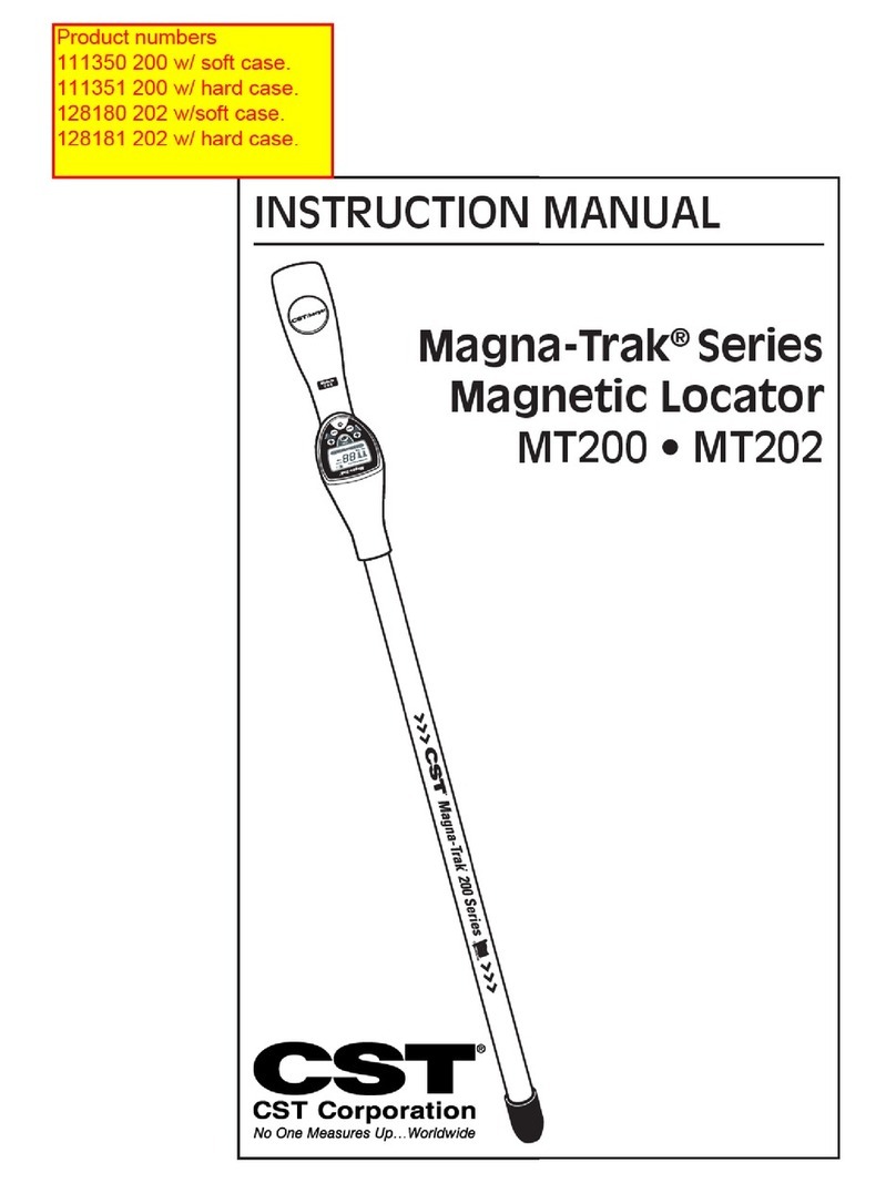
CST Magna-Trak 102 User manual

1
INSTRUCTION MANUAL
Magna-Trak 102®
Magnetic Locator

2
Introduction
The Magna-Trak 102 magnetic locator is a flux-gate type
of magnetometer which incorporates a unique patented tech-
nology that enables the factory to balance the magnetic sensing
coils to a finite condition. This patented method of magnetic
balancing is more advanced in the state-of-the-art technology.
The Magna-Trak 102 implements “peak response” over
ferromagnetic objects by yielding on increasing audio signal as
the object is approached and passed over.
This instrument is the product of many years of experience
and service provided by Chicago Steel Tape to the industry.
Table of Contents
Introduction ........................................................ 2
Theory of Operation............................................ 3
Features ............................................................. 4
Pictorial Description ........................................... 5
Basic Operation and Description ..................... 6-9
Field Operation................................................. 10
Signal Responses ........................................11-13
Locating Near a Steel Fence ............................ 14
Specifications, Warranty & Service ................... 15

3
Theory of Operation
The Magna-Trak 102 locator finds ferromagnetic objects
by sensing the magnetic field radiated by the object. The lo-
cator contains two sensor coil assemblies that are precisely
spaced and electronically balanced to achieve a near magnetic
balanced operating condition. In a uniform magnetic field, such
as the earth’s field, the two sensor coils maintain a magnetic
balanced status, because both of the coils experience the same
magnetic lines of force. However, when a ferromagnetic object
is approached the field strength and angle of the magnetic lines
upon each sensor is different. This difference, although minute,
is enough to offset the critical balance and produce an audible
indicating signal.
When no ferromagnetic objects are present, the speaker
emits a steady low frequency tone. As the object is approached,
the audio frequency increases until the center of the object is
directly beneath the locator’s lower tip. The frequency peaks
and then decreases as the object is passed. The peak indi-
cates the exact location of the object.
Nonferrous objects do not effect the locator. Objects made
of brass, aluminum, copper, etc. are ignored.
Sensor coils unbalanced by iron stake’s magnetic field.

4
Features
1. Instrument Control Panel
a) LCD Visual Display
b) Water-repellant push button switch operation
2. LCD Visual Display
a) Two digit numeric signal indicator
b) Expanding analog bar graph signal indicator
c) “Low Battery” alert flashing indicator
d) Displays “ferrous” model operation
e) “Caution: Power Line” alert flashing indicator
3. Water-repellant push button operation, single action
a) “ON” – power ON
b) “OFF” – power OFF
c) “ERASE” – Interferences such as a nearby fence are
virtually erased allowing the signal to return to the
normal audio tone.
4. Rugged high impact plastic enclosure with aluminum
sensor pole.
5. Powerful magnetic speaker constructed with waterproof
Mylar cone.
6. Six AA 1-1/2 volt battery operation.
7. 100 hour battery life under typical conditions.
8. Sensitivity control, single turn, continuously variable wide
range depth adjustment.
9. Volume control, single turn continuously variable
adjustment for selection of audio intensity.
10. Ergonomically designed for light weight, comfortable
balance for easy handling.
11. Flip out battery compartment cover for easy battery
access.
12. Signal “peaks” over magnetic objects.
13. Excellent depth capability.
14. Includes padded carrying case with shoulder strap or
hard case.
15. Deep tone audio under search conditions.
16. Water-resistant construction.

5

6
Basic Operation and Descriptions
Power On Button: Press once to activate the locator circuitry.
Simultaneously, the circuitry is automatically set to the proper
audio tone.
Power Off Button: Press once to turn the battery power off.
Volume Control: Rotate the knob to the desired audio sound
level. Full volume is achieved when the knob is turned full
clockwise.
Sensitivity Control: The sensitivity or depth range can be
varied with the rotation of the sensitivity knob. Maximum range
is provided at full clockwise rotation. The optimum setting is
determined by each particular application. Areas crowded with
various undesired ferrous metal may require a reduced sen-
sitivity level. Deeply buried objects being searched will require
the higher sensitivities.
Control Knob Decal: The markings for both the sensitivity
and volume control knobs are provided as a reference for
future settings or comparisons.
Speaker: When no magnetic metal is present the audio
sound heard will be a low frequency tone. As ferrous metals
are approached the audio tone will increase.
LCD Visual Display: Several visual display functions are pro-
vided for ease of operation as defined below.
Ferrous–Defines the basic function of the locator as a
“ferrous locator” (fixed indicator).
Digital Signal Indicator–A two digit numeric display
shows the relative signal level related to the audio
signal response being heard from the speaker. At the
lowest signal level when no magnetic metal is present
a small number will be viewed between “0” and “5”.
As metal is approached, the numbers will increase until
“95-99” is viewed. Deeply buried objects or lower sen-
sitivity levels will yield a lower peak number to aid in
pinpointing.

7
Analog Bar-Graph Signal Indicator–the bar graph
corresponds directly to audio frequency by expand-
ing outward from the center “diamond” as the signal
increases due to magnetic metals.
Low Battery Indicator–Although not visible under normal
conditions the LCD will display a flashing “Low Battery”
warning when the batteries fall below a predetermined
voltage. This alerts you to replace the batteries soon.
Several hours of battery life remains. However, in cold
temperatures this usable time may be shorter.
Power Line Indicator
Feature–The electro-
magnetic fields radiated
from buried or overhead
power lines are picked
up by the new sensitive
electronic circuitry and
internally transformed
into a visually flashing
indicator in the display
window as shown:
The distance or
detection range from the
cables where the locator responds depends on the
energy being carried by the electrical conductors. The
higher the energy, the greater the distance the locator
will respond to it. If the cables are dead (no electrical
connection or energy transfer), then no visual indica-
tion will appear.
When the locator is turned ON, this feature is
activated immediately. This feature only responds to
50 or 60Hz power line frequencies and not to tele-
phone or TV cables. This feature is intended as an
aid only and not to be used for locating or pin-
pointing electrical cables.
The magnetic detection operation and performance
of the magnetic locator are completely independent
from the power line indicator feature.

8
Erase Button: This is an optional button that is primarily used
in locations where large metal objects normally interfere with
the desired operation of magnetic locators. Cyclone fences,
metal buildings, vehicles and other large magnetic objects can
be electronically erased with this button.
The operation of this feature is best defined by explaining
the typical locator without this feature. For example, typical
magnetic locators will normally yield a screaming audio tone
when they are being operated in close proximity to a metal
fence. The magnetic field from this fence will usually override
the signal being sought from the buried object in search of.
The only option is to reduce the the sensitivity until the inter-
ference from the fence is minimized. However, the locator’s
sensitivity to the buried object is also minimized and usually
undetectable.
The new Magna-Trak 102 and its “Erase” feature solves
this problem by providing an Erase button; simply press this
button when the interference is annoying and the metal struc-
ture is electronically erased. The audio tone returns to the “no
metal” tone; the search continues and the buried object is lo-
cated.
This erasing action is functional within a reasonable circu-
ERASE
ZONE

9
lar area around the position of the locator in which the erase
button was pressed. This circular area, referred to as the erase
zone, may be affected by the magnitude of the magnetic field
of the fence and the distance from the fence when the button
was pressed. In extreme cases, there may be a point where
you may have to press the Erase button again as you approach
the fence.
If you inadvertantly erase the object you are directly over,
simply move the locator to one side and activate the Erase
button and return to a normal search procedure.
Battery Replacement: Turn the power off. Unscrew the
thumb screw on the battery cover between 2-5 turns. Lift the
cover off until the tab at the rear of cover clears the slot it is
located in. Remove the batteries by raising the batteries at the
junction or contact point of each set of two batteries. This is
the point where the two batteries contact each other. You may
prefer other methods of your choosing. Dispose of the weak
batteries properly. Insert the new batteries observing the po-
larity markings located inside the battery wells. Install the cover
in the reverse manner. Do not over tighten the thumb screw.
Do not replace the batteries under raining conditions, whereby
allowing water to enter the battery compartment.
Dead Batteries should be removed immediately-especially
before storage of the locator. Dead batteries are prone to leak-
age and may potentially damage the locator.
Replace all six batteries at once. Never selectively replace
batteries.
In the event the “Low Battery” indicator is not displayed,
no visual indications appear on the LCD window and no sound
is heard after pressing the power ON Switch–the batteries may
be completely dead. Check the battery compartment immedi-
ately.
Personal Items: Your magnetic locator is not only sensitive
to buried magnetic objects–it will also respond to items in your
possession. Ferrous objects such as steel tipped shoes, a
pocket knife, some wrist watches, key chains and other
magnetic objects will cause false signals during your search.

10
Field Operation
The recommended search position is a 45 degree angle from
the earth’s surface. Scan the locator pole from side-to-side in
a slow sweeping motion while walking in a uniform direction.
Once the object being searched is located, pinpointing the
objects location can be accomplished by holding the locator
vertical and sweeping it in an “X” pattern until the absolute peak
is found. Maintain a consistent height above the ground dur-
ing the side-to-side sweeping motion. The audio sound and vi-
sual LCD display will provide the pinpointing results shown.
Physical “X” Motion Shown
Locator’s Electrical
response
representation

11
a
a
a
a
a
a
a
aa
a
aa
aaa
a
a
a
a
a
a
a
aa
a
a
aa
a
a
a
a
a
aa
a
a
a
a
a
a
aa
a
a
a
a
a
a
a
a
a
a
a
a
a
a
a
aa
a
a
a
a
a
a
a
a
a
a
a
a
a
a
a
a
a
a
a
a
a
a
a
a
a
a
aa
a
a
a
a
a
a
a
a
a
a
a
a
a
a
a
a
a
a
a
a
a
a
a
a
a
a
a
a
aa
a
aa
a
a
a
a
a
aaa
a
aa
a
a
a
a
aa
a
a
a
a
a
a
a
a
a
a
a
a
a
aa
aa
a
a
aa
a
a
a
a
a
a
a
a
a
aa
a
a
aa
a
a
aaa
a
a
a
a
a
a
a
a
a
a
a
a
a
a
a
a
a
a
a
a
a
a
a
a
a
a
a
a
a
a
a
a
a
a
a
a
a
a
a
a
a
a
a
a
a
a
a
a
a
a
a
a
a
a
a
a
a
a
a
a
a
a
a
a
a
a
a
a
a
a
a
a
a
a
a
a
a
a
a
a
a
aa
a
a
a
a
a
a
a
a
a
aa
a
a
a
a
a
a
a
a
a
a
a
a
a
a
a
a
a
a
a
a
aaa
a
a
a
a
a
a
a
a
a
a
a
a
aa
a
a
a
a
a
a
a
aaa
a
a
a
a
a
a
a
a
aa
a
a
aa
a
aa
a
a
a
a
a
a
aa
aaa
a
a
a
a
a
a
a
a
a
a
a
a
a
a
a
a
a
a
a
a
a
a
a
a
a
a
a
a
a
aaa
a
a
a
a
a
a
a
a
aaa
a
aaa
a
Signal Response
Below is an example of audio and LCD visual signal responses
to (1) no object, (2) one small deeper metal target and (3) a
second larger and shallower metal object. The LCD display in-
dicates both the numeric digital and analog bar-graph response
as the locator passes over the ground.
(1) (2) (3)

12
Typical Signal Responses
The metal handles on the septic tank cover will provide a us-
able signal to determine the location of the actual cover.
Signal Response
The metal handles on a septic tank cover
Large metal objects may cause double signals as indicated.
The center of the cover is found by sweeping the locator back
and forth to create a ring pattern response. The center null will
designate the cover’s center.
Signal Response
Sewer cover

13
Typical Signal Responses
Water Locations:
The locator can be submerged into water with the pole sec-
tion to just under the plastic case.
a
a
a
a
a
a
a
aa
a
aa
aaa
a
a
a
a
a
a
a
aa
a
a
aa
a
a
a
a
a
aa
aa
a
a
a
a
aa
a
a
a
a
a
a
a
a
a
a
a
a
a
a
a
aa
a
a
a
a
a
a
a
a
a
a
a
a
a
a
a
a
a
a
a
a
a
a
a
a
a
a
aa
a
a
a
a
a
a
a
a
a
a
a
a
a
a
a
a
a
a
a
a
a
a
a
a
a
a
a
a
aa
a
aa
a
a
a
a
a
aaa
a
aa
a
a
a
a
aa
a
a
a
a
a
a
a
a
a
a
a
a
a
aa
aa
a
a
aa
a
a
a
a
a
a
a
a
a
aa
a
a
aa
a
a
aaa
a
a
a
a
a
a
a
a
a
a
a
a
a
a
a
a
a
a
a
a
a
a
a
a
a
a
a
a
a
a
a
a
a
a
a
a
a
a
a
a
a
a
a
a
a
a
a
a
a
a
a
a
a
a
a
a
a
a
a
a
a
a
a
a
a
a
a
a
a
a
a
a
aa
a
a
a
a
a
a
a
aa
a
a
a
a
a
a
a
a
a
aa
a
a
a
a
a
a
a
a
a
a
a
a
a
a
a
a
a
a
a
a
aaa
a
a
a
a
a
a
a
a
a
a
a
a
aa
a
a
a
a
a
a
a
aaa
a
a
a
a
a
a
a
a
aa
a
a
aa
a
a
a
a
a
a
a
a
a
aa
aaa
a
a
a
a
a
a
a
a
a
a
a
a
a
a
a
a
a
a
a
a
a
a
a
a
a
a
a
a
a
aaa
a
a
a
a
a
a
a
a
aaa
a
aaa
a
a
a
a
a
a
aaa
a
a
a
a
a
aa
a
a
a
a
a
a
a
a
a
a
a
aaa
a
a
a
a
a
a
a
a
aaa
a
a
a
a
a
a
a
aa
a
a
a
a
a
a
a
a
a
a
a
a
a
a
a
a
a
a
a
a
a
a
a
a
a
a
a
aaa
a
a
a
a
a
a
a
a
aa
a
a
a
a
a
a
a
a
a
a
a
aaa
a
aa
a
a
a
a
a
a
a
a
a
a
a
a
a
a
a
a
a
a
a
a
a
a
a
a
a
a
a
a
aa
a
a
a
a
a
a
a
a
a
a
a
a
a
a
a
a
a
a
a
a
a
a
a
a
a
a
a
a
a
a
a
a
a
a
a
a
a
a
aa
a
a
aa
a
a
a
a
a
a
a
a
a
a
a
a
a
a
a
a
a
a
a
a
a
a
a
a
a
a
a
a
a
a
a
a
aa
a
a
aaa
a
a
a
aaaa
a
a
a
a
a
a
a
a
a
a
a
a
a
a
a
a
a
a
a
a
a
a
a
a
a
a
a
a
a
a
aa
a
a
a
a
a
a
a
a
a
a
a
a
a
a
a
a
a
a
a
a
a
a
a
a
a
a
a
a
a
a
a
a
a
a
a
a
a
aa
a
a
a
a
a
a
a
a
a
a
a
a
a
a
a
a
a
a
a
a
a
a
a
a
a
a
a
a
a
aa
a
a
a
a
aa
a
a
a
a
a
a
a
a
aa
a
aa
a
a
a
a
a
a
a
a
aa
a
a
a
a
a
a
a
a
a
a
a
a
aa
a
a
a
a
a
a
a
a
a
a
a
a
a
a
a
a
a
a
a
a
a
a
a
a
a
a
a
a
a
a
a
aa
aaaa
a
a
a
a
a
a
a
a
aa
a
a
a
a
a
a
a
a
aa
a
a
a
a
a
a
aaa
a
a
a
a
a
a
a
a
a
a
a
a
a
a
a
a
a
a
aa
a
a
a
a
a
a
a
aaa
a
a
aa
a
a
a
a
a
a
a
aaa
a
a
a
aa
a
a
a
a
a
a
a
a
a
a
a
a
a
a
a
a
a
a
a
a
a
a
a
a
a
a
a
a
a
a
a
a
a
a
a
a
a
a
a
a
a
aa
a
a
a
a
a
a
a
a
a
a
a
a
a
a
a
a
a
a
aa
a
a
a
a
a
a
a
a
a
a
aa
a
a
a
aa
a
a
aa
a
a
aaa
a
a
aaa
a
a
a
a
a
a
a
a
a
a
a
a
a
a
a
a
a
a
a
a
a
a
aa
a
a
a
a
a
a
a
a
a
a
a
a
a
a
a
a
a
a
a
a
a
a
a
a
a
a
a
a
aaa
a
a
a
a
aa
a
aa
a
a
a
a
aa
a
a
a
a
a
a
a
a
a
a
a
a
a
a
a
a
a
a
a
a
a
aa
a
a
a
a
a
a
a
a
a
a
aa
a
a
a
a
a
aa
a
a
a
a
a
a
a
a
a
a
a
a
a
a
a
a
aaa
aa
a
aa
a
aa
a
a
a
aa
a
aa
a
a
a
a
a
a
a
a
a
a
a
aaaa
a
a
a
a
a
a
a
a
a
a
a
a
a
a
a
aa
aa
a
a
a
a
a
a
a
a
a
a
a
a
a
a
aa
a
a
a
a
a
a
a
a
a
a
a
a
a
aa
a
a
a
a
a
a
aaa
a
a
a
a
aaaa
a
a
a
a
aa
a
a
a
a
a
a
a
aa
a
a
a
a
a
a
a
a
aa
a
a
a
a
a
a
a
a
a
a
a
a
aa
a
a
a
a
a
a
a
a
a
aaa
a
a
aa
a
aaaaa
a
a
a
a
a
a
a
a
aa
a
a
a
a
a
a
a
a
a
a
a
a
a
a
a
a
a
a
a
a
a
aa
a
a
a
aa
a
aa
a
a
a
a
a
a
aaa
a
aa
a
a
a
a
a
a
a
a
a
a
a
a
a
a
a
a
a
a
a
a
a
a
a
a
a
a
a
a
a
a
aa
a
a
a
a
a
a
a
a
a
a
a
a
a
a
aaaa
a
a
a
a
aaa
a
aa
a
a
a
a
a
a
a
a
aa
a
a
a
a
a
a
a
a
a
aa
a
a
a
a
aa
a
a
a
a
a
a
a
a
a
aaa
a
a
a
aa
a
a
a
aa
a
a
a
a
a
aa
a
a
a
a
a
a
a
Hold the locator in a vertical position while searching to pro-
duce the best results.
The joints, elbows and ends will create the strongest signals.
Cast iron pipe, joints, elbows, etc.

14
Locating Near a Steel Fence
Approach the fence and stop at the distance at which you wish
to begin your search. While holding the locator in a vertical
position, press and release the “erase” button on the membrane
panel. Begin sweeping the locator side to side parallel to the
fence. As you move toward or away from the fence during the
sweeping motion, at some point you may have to press the
“erase” button again.
Continue this process throughout the search. The need to re-
activate the “erase” circuitry depends on the proximity from the
fence and the magnetism of the fence itself.
Searching Under an Unattended Vehicle
In the event you must search under an parked vehicle that is
unattended, you can simply slide the sensor pole under the
vehicle and activate the “erase” feature. Slide the sensor pole
side to side until you locate the target.
SWEEP
SPACING

15
Specifications
Power: Six AA 1 1/2 volt batteries
Battery life: 100 hours of intermittent operation (alkaline batteries)
Output: Powerful magnetic speaker with water proof Mylar cone.
LCD Display: Numeric digital, analog Bar-graph and low battery indicator
feature.
Weight: Approximately 3 lbs. (1.3kg) with batteries.
Operating temperature: 0°F to 120°F (-18°C to 49°C).
Length: 40 inches (101.6 cm.).
Construction: High impact plastic, water resistant, light weight and epoxy
painted. Aluminum sensor tube waterproof to just under
the plastic case (see page 13).
Patent: United States #4,439,732.
Nominal sensor 20 inches (50.8 cm.).
Warranty
The Magna-Trak 102 magnetic locator is warranted to be free from
defects in materials and workmanship for a period of five years af-
ter the delivery of the product to the original user. Our liability un-
der this warranty is limited to replacing any defective parts, adjust-
ing and servicing any instrument or, at the company’s option, re-
placement of the instrument returned by the original user, trans-
portation charges prepaid, to the company. If the malfunction has
been caused by misuse or abnormal conditions of operation, re-
pairs will be billed to the user, with a cost estimate submitted prior
to commencing repair work.
Batteries and the battery holder are not covered by this warranty.
Include model, serial number and a written description of the
problem encountered with the instrument with the return of the
locator.
All Magna-Trak 102 locators repaired out of warranty carry a
warranty on replaced parts for a period of 90 days.
Service
If your magnetic locator needs service, you may return it to the dealer from
which it was purchased or send it directly to the factory. Include your name,
address, where purchased, date of purchase, and a description of the
problem(s).

16 Magna-Trak 102 made in Watseka, Illinois, USA
GG12961000 Rev. 2
450 S. CIPS Street
P.O. Box 359
Watseka, IL 60970 USA
(815) 432-5237 FAX (815) 432-2417 Toll Free: (800) 435-1859
http://www.cstsurvey.com sales@cstsurvey.com
Chicago Steel Tape Berger Magna-Trak® LaserMark™ Tru-Lock™
Table of contents
Other CST Metal Detector manuals
Popular Metal Detector manuals by other brands

Bounty Hunter
Bounty Hunter Ultra Mag Sharp Shooter owner's manual

Bounty Hunter
Bounty Hunter Land Ranger owner's manual
Pyle
Pyle PMD43 manual
Minelab
Minelab Sovereign XS-2 Pro instruction manual
Ceia
Ceia HI-PE/CF Series Additional information
XP Metal Detectors
XP Metal Detectors DEUS II quick start guide

Elenco Electronics
Elenco Electronics K-26 Assembly and instruction manual

Jaycar
Jaycar QP-2307 owner's manual

AQUASCAN INTERNATIONAL
AQUASCAN INTERNATIONAL AQUAPULSE 1B operating instructions

Ceia
Ceia PD240CH instruction manual
Minelab
Minelab F1A4 Operator instructions

XP
XP Gold MAXX Power instruction manual
