Ceia PD240CH User manual

www.ceia.net
PD240CH
INSTRUCTION MANUALAAAAAAA
FI100K0025v1100UK
CEIA reserves the right to make changes, at any moment and without notice, to the models
(including programming), their accessories and options, to the prices and conditions of sale.

.
FI100K0025v1100 UK - - PD240CH
INSTRUCTIONS MANUAL
Contents
1DESCRIPTION ......................................................................................................2
1.1General Description...............................................................................................2
1.1.1Purpose .................................................................................................................2
1.1.2Block diagram........................................................................................................2
1.1.3Detection principles and detector capabilities........................................................2
1.1.4Operating features.................................................................................................2
1.2Main Components..................................................................................................3
1.3Controls and Indicators..........................................................................................4
1.4Marking..................................................................................................................4
2USE .......................................................................................................................5
2.1Turning on..............................................................................................................5
2.2Status verification ..................................................................................................5
2.3Selection of alarm or diagnosis alert indications....................................................6
2.3.1Acoustic alarm or diagnosis alert...........................................................................6
2.3.2Vibrating alarm.......................................................................................................6
2.4Selection of the Analysis Mode..............................................................................6
2.5Metal mass detection.............................................................................................7
2.5.1Two-step localization procedure (Pin-Pointing).....................................................8
2.5.2Alarm Reset...........................................................................................................8
2.6Operational verification..........................................................................................9
2.7Simultaneous use of HHMDs and WTMDs............................................................9
2.8Automatic stand-by..............................................................................................10
2.9Automatic turning off............................................................................................10
2.10Turning off............................................................................................................10
2.11Battery Charging..................................................................................................11
2.11.1Battery charge level.............................................................................................11
2.11.2Procedure for recharging the battery...................................................................11
3MAINTENANCE ..................................................................................................12
3.1Periodic maintenance..........................................................................................12
3.1.1Cleaning...............................................................................................................12
3.1.2Battery .................................................................................................................12
3.2Troubleshooting...................................................................................................12
3.3Procedure for replacing batteries.........................................................................13
4APPENDICES .....................................................................................................14
4.1Specifications.......................................................................................................14
4.2Spare Parts..........................................................................................................15
4.3Options and Accessories.....................................................................................16
PD240CH . FI100K0025v1100 UK 00
Symbols
This sign in the manual indicates tips for optimizing the device’s
performance.
CEIA reserves the right to make changes, at any moment and without notice, to the models
(including programming), their accessories and options, to the prices and conditions of sale.
i

Instructions 1
FI100K0025v1100 UK - - PD240CH
General warnings
Read this manual carefully before
installing, operating or carrying out
maintenance on the device. Keep
the manual in a safe place for
future reference, and in perfect
condition.
Follow the instructions contained in
this manual for all operations
relating to installation, use and
maintenance of the device. CEIA
cannot be held responsible for any
damage resulting from procedures
which are not expressly indicated
in this manual, or from any lack of
attention, either partial or total, of
the procedures described therein.
All personnel operating with or
performing operations on the
device must have an adequate
preparation and shall know the
procedures described in this
manual.
Any modification to the
configuration setup by CEIA is
forbidden and voids all warranties
and certifications.
This manual must accompany the
device described therein in the
case of change of ownership, and
until the device is broken up.
CEIA is not responsible for
direct or indirect harm to people
or things due to incorrect use of
the equipment.
Correct and Forbidden Use and
Operating Limits
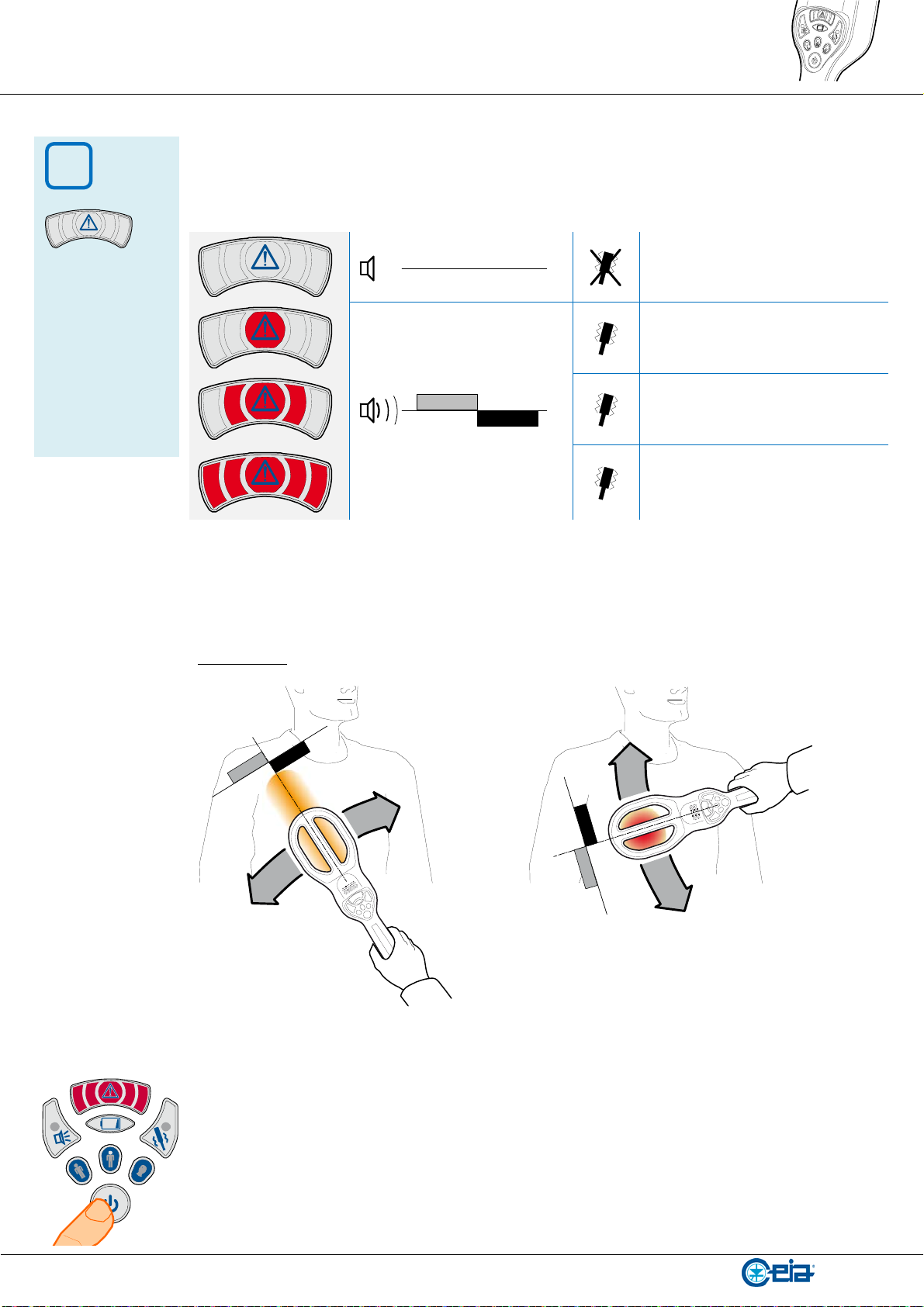
Correct Use: A Metal Detector is a
unit that reacts to the metal masses
present in close proximity. As part of
the normal screening process, the
metal detector must scan manually the
surface of the person or object to
inspect.
Forbidden Use: Any use different
from that described in this manual is
forbidden.
Operating limits: Refer to the
“Technical Characteristics” section.
Safety Information
Compliance with standards for
human exposure to electromagnetic
fields
CEIA Metal Detectors comply with
applicable regulatory requirements for
human exposure to electromagnetic
fields. CEIA submits its devices to
testing by bodies qualified to check
compliance with the emission limits of
the main standards currently in force
(documentation available on request).
Safety for Medical Devices
The electromagnetic field emitted by
CEIA Metal Detectors is extremely
weak, with an amplitude comparable
with that of the earth. However, CEIA
cannot exclude that this device may
affect personal medical electronic
devices, depending on their
functionality or their restrictions on
use. Any recommendation or directive
issued by medical personnel or
medical equipment manufacturers
relating to electromagnetic fields must
therefore be implemented. If for any
reason a person about to be analyzed
through the detector shows fear or
refuses to undergo the inspection, it is
recommended that the inspection be
carried out using an alternative
method.
For further information on standard
procedures to be followed for
inspection of people with implanted
medical devices using a metal
detector, please consult the ASTM
F2401-04 standard “Standard Practice
for Security Checkpoint Metal Detector
Screening of Persons with Medical
Devices” or other relevant directives.
CEIA is not responsible for direct or
indirect harm to people or things
due to incorrect use of the Metal
Detector.
Use warnings
The final user is responsible for
selecting the appropriate security
level/sensitivity for their application.
After this selection has been made,
it is also the final user's
responsibility to verify calibration
using the test object(s) appropriate
to the level of security selected.
Additionally, this test should be
carried out periodically to insure no
changes have occurred in the
equipment. Reference Standards
on this argument include
documents ASTM C 1270-97 and
ASTM C 1309-97.
The final user is responsible for
determining and implementing the
appropriate inspection procedures
and for the training of personnel
involved in carrying them out.
The information contained in this
manual is provided only as a
technical reference for use and
maintenance, and does not contain
operational procedures.
Handle the device with care and
without excessive force during use.
If the device is stored for a long
period in temperatures outside the
operating range, wait for the
temperature of the detector to
come back within that range before
switching on.
Important advice regarding the
batteries incorporated in the
device. When replacing: use CEIA
spare parts or batteries with
equivalent electrical/mechanical
characteristics. Do not dispose of
used batteries in general rubbish
bins; use public battery collection
facilities as per local regulations, or
return them to a CEIA office. If the
equipment is to be disposed of,
remove the batteries and dispose
of them separately.
Maintenance warnings
Carry out the periodic maintenance
regularly (see section on
Maintenance).).
Do not wash the device with water,
liquid detergents or chemical
substances. Use a slightly moist,
non-abrasive cloth for cleaning.
Read the chapter “Maintenance”
carefully before calling the service
centre. Whatever the problem, only
specialized service personnel
authorized to work with CEIA
equipment should be called.
Harmlessness to Magnetic Media
The device is safe for items carried by
people, including all common
magnetic media such as magnetic
cards, floppy disks and tapes
(conforming to NIST - NBS 500-101
“Care and Handling of Computer
Magnetic Storage Media”).

2 Description
FI100K0025v1100 UK - - PD240CH
1 Description
1.1 General Description
1.1.1 Purpose
PD240CH is a lightweight portable metal detector which is capable to distinguish magnetic
metals with respect to nonmagnetic metals. Potential threats for MRI scans can be hence
revealed and distinguished from non-dangerous prosthesis or implants.
This equipment is designed to localize metal masses concealed or carried on a person or
an object. As part of the normal screening process, the detector must scan manually the
surface of the person or object to inspect.
1.1.2 Block diagram
The detector set consists of:
the Metal Detector, containing the following functional blocks:
ogenerator of time-varying magnetic field FG, connected to an antenna
ocontrol and processing unit PCU, which determines if the variation of the
received signal is due to a metal mass MO .
ocontrol panel CP
obattery B
Block diagram
1.1.3 Detection principles and detector capabilities
The detector emits an electromagnetic field in the area to be inspected. A metal mass
present in this area causes a field absorption which is compared with an alarm threshold
to set off a proper signaling device.
Effective sensitivity to all metals, full compliance with the latest Security Standards and
high immunity to external metal masses are among the main peculiarities of this device.
1.1.4 Operating features
Refer to “Specifications” section.

Description 3
FI100K0025v1100 UK - - PD240CH
1.2 Main Components
# Part list
1 Hand Held Metal Detector
2 Desktop docking station
HHDS-CH
3 Verification of Detection test
piece , code 72131
4 Universal AC adapter
5 EU, UK, USA, JP plugs
6 Instruction Manual
7 Carry bag
8 Verification of Discrimination
test piece , code 72132
PD Set inside the Carry Bag
3
1
4
5
6
7
2
8
1
2
3
8

4 Description
FI100K0025v1100 UK - - PD240CH
1.3 Controls and Indicators
Optical alarm indicator
RED: metal mass alarm
During start-up it provides further indications.
Battery level
indicator
OFF: battery life
>1h (approx.)
Blinking: low
battery
Steadily lit:
battery discharged
Selection of the
acoustic alarm
signal
Press to enable
(inner lamp on) or
disable (inner lamp
off) the alarm
indication.
Alarm buzzer
Selection of the
vibrating alarm
signal
Press to enable
(inner lamp on) or
disable (inner lamp
off) the alarm
indication.
Analysis Mode
selection
Press the proper
push button.
Head: high sensitivity
to very small magnetic
metals. Insensitive to
medium size
nonmagnetic metal
items
Body: high sensitivity to
small magnetic metals.
Insensitive to large
nonmagnetic metal
items
All-metals: high
sensitivity to all types
of metals
ON/OFF switch
Press to turn the device on.
Keep pressed for at least 3 seconds to
switch the device off.
Press briefly to display the current state of
the device and/or to reset a continuous
alarm.
1.4 Marking
Equipment marking is located in the lower side,
near the handle.
The data provided are as follows:
model
serial number (SN)
power supply voltage and consumption
battery type and quantity
PD240CH
SN xxxxxxxxxxx
3V 370mW
Battery Size AA or LR6 x2

Use 5
FI100K0025v1100 UK - - PD240CH
2 Use
2.1 Turning on
Press push button. The red central light of the alarm indicator turns on.
The battery level is displayed for approx. 2 seconds through a green bar-graph.
< 30% 30% … 70% >70%
The detector is “ready for use” when all alarm indications stop (approx. 2 seconds after
turning on).
The lights inside the push buttons “alarm signaling mode” and “sensitivity selection” blink
according to the current setting.
Example of “ready for use” indication: acoustic alarm enabled and “body” mode setting.
2.2 Status verification
The device settings are indicated by a periodic flashing of the inner lights of the selection
push buttons. The same indication is also displayed by pressing push button briefly.
Keep away
from metal
objects during
start-up!

6 Use
FI100K0025v1100 UK - - PD240CH
2.3 Selection of alarm or diagnosis alert indications
2.3.1 Acoustic alarm or diagnosis alert
Press push button to enable the buzzer. The light inside the button starts blinking.
Press again to disable the signal.
2.3.2 Vibrating alarm
Press push button to enable the vibrating alarm indication. The light inside the button
starts blinking. Press again to disable the indication.
2.4 Selection of the Analysis Mode
Three analysis modes, selectable via keypad interface, are available:
All-metals:
high sensitivity to all types of metals (examples: implanted medical devices,
prostheses, metal splinters)
Body:
high sensitivity to small magnetic metals (example: ferromagnetic fragments,
surgical instruments).
Insensitive to large nonmagnetic metal items (example large prostheses)
Head:
high sensitivity to very small magnetic metals (example: small ferromagnetic
fragments).
Insensitive to medium size nonmagnetic metal items (example: non-
ferromagnetic dental implants, small prostheses).

Use 7
FI100K0025v1100 UK - - PD240CH
2.5 Metal mass detection
Scan the person’s body sweeping slowly the detector
(max. speed: 50cm/second) close to the surface to
inspect (distance: approximately 1 cm).
Move the detector gently and do not bump it against
the person, in order to prevent harm to the patient.
If necessary, change the Analysis Mode to scan
properly each part of the person’s body. Each
Analysis Mode is optimized for a specific aspect, but
its use can be valued depending on the specific
needs.
Keep the detector far from metal masses:
ground : minimum distance of 40 cm
large size metal objects, such as furniture, metal frames, walls and doors:
minimum distance of 50cm.
For this purpose, the person to scan should be lying on a metal free support. The figure
below shows an example of a gurney mainly made of plastic: the shaded area is metal
free, while the castors can contain metallic parts.

8 Use
FI100K0025v1100 UK - - PD240CH
When a metal mass is detected, the alarm indicator provides a RED signal proportional to
the size (small/medium/large) or the distance of the object.
A dual-tone audio indication is also provided. The center of the target corresponds to the
tonal change.
No metal mass
Small metal mass
TONE A
TONE B
Medium metal mass
Large metal mass
2.5.1 Two-step localization procedure (Pin-Pointing)
When the device detects a target, the change of the alarm tone indicates the centerline of
an area where it is probably located.
To obtain a more precise localization, sweep with crossed axis in order to determine the
center point of the target.
TONEA
TONEB
TONEA
TONEB
2.5.2 Alarm Reset
The detector can trigger an alarm when placed near to a large size metal mass.
In this case, move away the detector from the metal mass: the alarm will reset
automatically. A prolonged alarm can be quickly reset, by pressing the ON/OFF button
briefly.
Do not reset the detector when placed near to a large size metal mass!
i
The optical
alarm signal is
always enabled,
except for
specific
customer‘s
request.

Use 9
FI100K0025v1100 UK - - PD240CH
2.6 Operational verification
The calibration test pieces included in the
set allows the operator to perform a quick
check of the detection capability and
discrimination, using the Detection Test
Piece (code 72131) and the Discrimination Test
Piece (code72132).
Procedure
Verification with “HEAD” analysis mode
Select “HEAD” analysis mode and pass the Detection Test Piece close to the bottom
side of the detector with the “HEAD” side facing it. The test piece must pass over the
centerpoint of the sensing area. An alarm signal must be provided.
Pass the Discrimination Test Piece as above while keeping it aligned to the detector.
No alarm signal must be provided.
Head Body
Verification with “BODY” analysis mode
Select “BODY” analysis mode and pass the Detection Test Piece close to the bottom
side of the detector with the “BODY” side facing it. The test piece must pass over the
centerpoint of the sensing area. An alarm signal must be provided.
Pass the Discrimination Test Piece as above while keeping it aligned to the detector.
No alarm signal must be provided.
HeadBody
Verification with “ALL-METALS” analysis mode
Select “ALL-METALS” analysis mode and pass the Detection Test Piece close to the
bottom side of the detector with the “HEAD” side facing it. The test piece must pass
over the centerpoint of the sensing area. An alarm signal must be provided.
Pass the Discrimination Test Piece as above while keeping it aligned to the detector.
An alarm signal must be provided.
Head Body
2.7 Simultaneous use of HHMDs and WTMDs
The Hand Held Metal Detector can be used close to a Walk-Through Metal Detector at the
distance usually kept for secondary inspections.

10 Use
FI100K0025v1100 UK - - PD240CH
2.8 Automatic stand-by
Metal free table
Standard Stand-by mode
The device enters stand-by mode, reducing power consumption,
in case of no operation for 3 minutes (time adjustable on
customer request).
Stand-by after 180s
This function is enabled by default, but can be disabled on customer request
or using HHMD Configuration Tool. .
Table with metal parts
Quick Stand-by mode
In case the detector rests facing up, as illustrated in the figure on
the left, on a horizontal surface containing metal parts, the unit
quickly enters stand-by mode, after a short alarm.
Alarm immediate Stand-by
This function is disabled by default, but can be enabled on customer request
or using HHMD Configuration Tool.
Restart
To restart the unit, simply move it: the detector will be
immediately ready for use.
2.9 Automatic turning off
The device switches off completely after a stand-by state exceeding 40 minutes (time
adjustable on customer request).
This function can be disabled, on customer request or using HHMD Configuration Tool.
2.10 Turning off
Keep pressed push button for at least 3 seconds. RED lights will turn on in sequence
and then the device turns off (all indicators off).
>3s

Use 11
FI100K0025v1100 UK - - PD240CH
2.11 Battery Charging
2.11.1 Battery charge level
When the battery is almost discharged the level
indicator blinks in YELLOW. The detector is still
operational for approx. 1 hour. During this
time the detection capability and all the other
performances of the unit are not affected.
When the battery is completely discharged, the
level indicator remains steadily on and a
continuous tone is emitted by the buzzer: stop
operations and recharge the battery.
2.11.2 Procedure for recharging the battery
Connect the AC/DC adapter cable to the HHDS unit. Connect the adapter to the AC line.
OFF
HHDS
desktop docking station
Place the detector inside the receptacle of the HHDS. The charging process will start
immediately. If still powered on when placed inside the charger, the detector switches off
automatically.
After about 5 seconds an ORANGE alarm
light starts blinking (charging in progress). The
orange indication is proportional to the battery
charge level.
At full charge (after 5 hours max.) the
indicator turns in steady GREEN light. The
detector is ready for use.
< 30%
30% … 70%
>70%
100%
Keep the
battery charger
pins clean, to
ensure proper
electric
contact.
i
At full charge the
detector can
remain inside
the recharger
indefinitely
without damage.
The detector can
be extracted and
used even
before the full
charge is
completed If
required.

12 Maintenance
FI100K0025v1100 UK - - PD240CH
3 Maintenance
3.1 Periodic maintenance
3.1.1 Cleaning
Use a slightly moist, nonabrasive cloth for cleaning.
Do not wash the device with liquid detergents or chemical substances.
3.1.2 Battery
Keep the battery charger pins present on the metal detector handle and on the HHDS
module clean, to ensure proper electric contact.
In case of a prolonged period of storage/unuse Ni-MH batteries lose naturally
almost all their charge and then they might have difficulties in recharging. In
order to prevent that, we recommend that they undergo a complete charge
cycle at least every 4 months even when unused. Recharge the batteries every
month to keep them always ready to use (charge at 80% or more).
3.2 Troubleshooting
Signal or symptom Probable cause Action
Alarm signal after start-
up.
Start-up carried out
near a metal mass.
Move the deìector away from the
metal mass and reset the detector
(refer to section “Alarm Reset”.
Electromagnetic
sources present near
the detector:
- Other hand-held
metal detectors
with the same
operating channel
Use hand-held metal detector with
different operating channel (using
the accessory HHMD Configuration
Tool ).
- Walk-through metal
detectors or other
electromagnetic
sources in close
proximity
Increase distance.
Use hand-held metal detector with
different operating channel (using
the accessory HHMD Configuration
Tool ).

Maintenance 13
FI100K0025v1100 UK - - PD240CH
Signal or symptom Probable cause Action
Both intermittent RED
alarm and audio signals
during use.
Fault Discontinue equipment use and
contact service department.
Operational verification
failure. Test procedure carried
out incorrectly.
Power cycle the detector, wait for
“ready for use” signal and repeat the
procedure correctly.
In case of repeated failure,
discontinue equipment use and
contact service department.
Battery charging process
does not start.
Wrong procedure or
dirty electric contacts.
Extract the detector from HHDS
module and verify that it is off. Verify
that the HHDS is connected to the
AC power supply. Place again the
detector inside the HHDS module.
In case of repeated failure:
- Verify that the AC power supply
is available
- Check that the contacts of the
detector and the spring pins of
the HHDS are clean and
working properly
- replace HHDS module
In case of repeated failure,
discontinue equipment use and
contact service department.
Intermittent RED alarm
during battery charging
process
Dirty electric contacts
Check that the contacts of the
detector and the spring pins of the
HHDS are clean and working
properly.
Damaged battery,
absent or wrongly
inserted.
Check the batteries condition and
replace them if necessary (see
procedure below).
3.3 Procedure for replacing batteries
Remove the locking screw from the cap of the battery compartment, using a TORX 10
key. Replace the batteries, respecting their polarity, as illustrated in the figure below.
Replace the battery compartment cap and secure it tightening the locking screw.

14 Appendices
FI100K0025v1100 UK - - PD240CH
4 Appendices
4.1 Specifications
POWER SUPPLY Metal Detector: 2 x AA size Ni-MH, 2500mAh rechargeable
batteries
HHDS-CH AC/DC adapter: 100-240V~, 50-60Hz, 175 mA
max.
CONTROL PANEL
Optical, acoustic and vibratory alarm modes
3-level analysis mode selection buttons:
All Metals (magnetic and non magnetic metals)
Body (small magnetic metals)
Head (very small magnetic metals)
DETECTION AND
OPERATIONAL FEATURES Customizable via HHMD Configuration tool
BATTERY Battery life (AA NiMH batteries 2500mAh):
All Metals: > 50 hours
Body: > 18 hours
Head: > 20 hours
Low battery indicator
OPERATING
TEMPERATURE -40°C … +70°C (-35°F to 158°F)
STORAGE TEMPERATURE -40°C … +80°C (-35°F to 176°F)
RELATIVE HUMIDITY 0…98% (without condensation)
DIMENSIONS PD240CH: 405mm x 120mm x 40mm (15.9" x 4.7" x 1.6")
HHDS-CH: 175mm x 115mm x 85mm (6.9" x 4.5" x 3.4")
Carry Bag: 430mm x 340mm x 105mm (16.9" x 13.4" x 4.1”)
WEIGHT PD240CH(with battery): 460g (1.05 lbs)
HHDS-CH (with power adapter): 755 g (1.66 lbs)
Carry Bag: 1.33 kg (2.9 lbs)
MANUFACTURED IN SHOCK-RESISTANT TECHNICAL POLYMERS
COMPLIANCE Conforms to the international standards currently applicable
for safety, EMC and to the applicable CE regulations
.
Warranty
The warranty on all CEIA products, extended to the period agreed with the Sales Department, is applicable to
goods supplied from our factory, and for every constituent part thereof, with the exception of the batteries. Any
form of tampering with the device, and in particular opening its container, is strictly forbidden and will
invalidate the warranty.
Customer Satisfaction Report
C.E.I.A. objective is the maximum quality of products and services offered to the customer. Any comments
and suggestions useful for achieving this objective will be highly appreciated and can be sent to us by
compiling and returning the form available at:
http://www.ceia.net/security/satisfaction

Appendices 15
FI100K0025v1100 UK - - PD240CH
4.2 Spare Parts
Detection test piece
Test piece for the
verification of the detection
capability during
Operational Verification,
Code: 72131
Discrimination test piece
Test piece for the
verification of the
discrimination during
Operational Verification
Code: 72132
Carry bag
Carry bag for complete PD
Set.
Code: 66058
Batteries
2 size AA rechargeable
batteries NiMH, 2500mAh.
TORX10 key Included.
Code: 60769
HHDS desktop docking
station.
Desktop docking station
with AC power supply
adapter.
Code: HHDS-CH
Multi-plug AC power
supply adapter for HHDS.
AC power supply adapter
for HHDS, with EU, UK,
USA/JP interchangeable
plugs.
Code: 64643

16 Appendices
FI100K0025v1100 UK - - PD240CH
4.3 Options and Accessories
HHMD Configuration Tool
Tool for setting up the metal
detector via USB PC-HHMD
connecting cable and GUI
interface.
Code: 63537


www.ceia.net
Table of contents
Other Ceia Metal Detector manuals