CSW Smoke Guard 2100 User manual

Model 2100
|
Smoke and Fire Curtain
287 N. Maple Grove. Boise, ID 83704
P. (800) 574-0330 F. (208) 639-7851
info@smokeguard.com
Installation Manual

2
Table of Contents
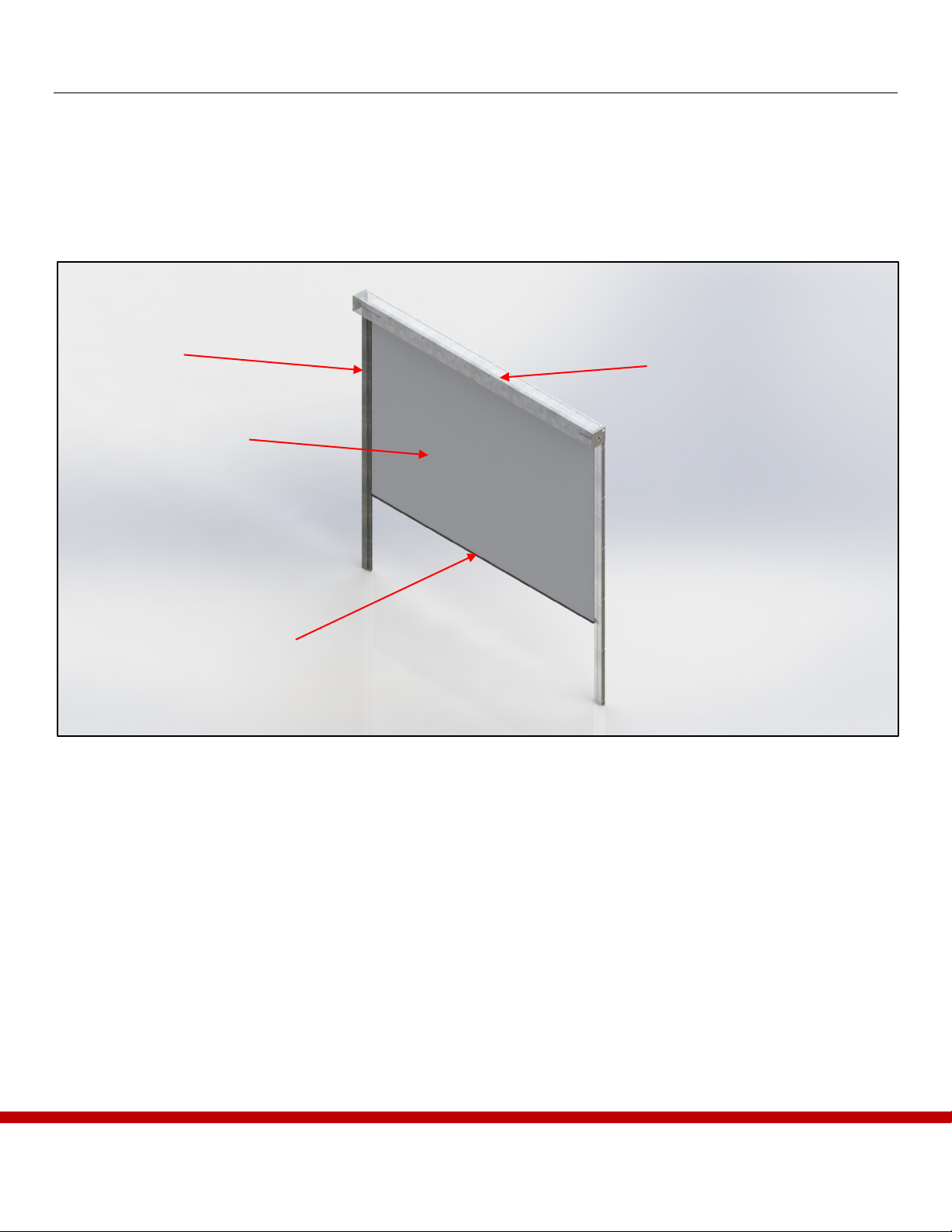
Section 1 – System overview ............................................................................................................................... 3
1.1 – Major Components..................................................................................................................................... 3
Section 2 – Main Controller and Conduit Routing.............................................................................................. 4
2.1 – Optional Wireless Jogger ........................................................................................................................... 5
2.2 – Checklist..................................................................................................................................................... 5
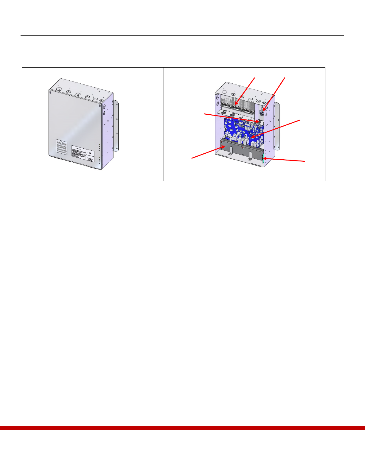
Section 3 – Main Controller Installation.............................................................................................................. 6
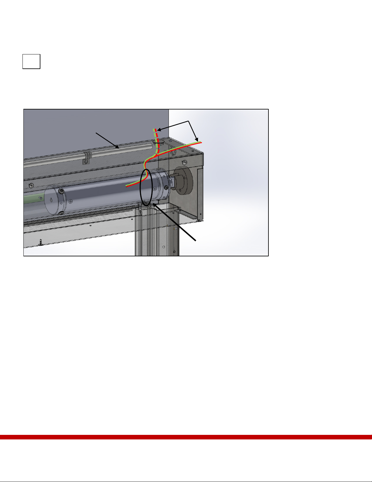
Section 4 – Housing Installation .......................................................................................................................... 7
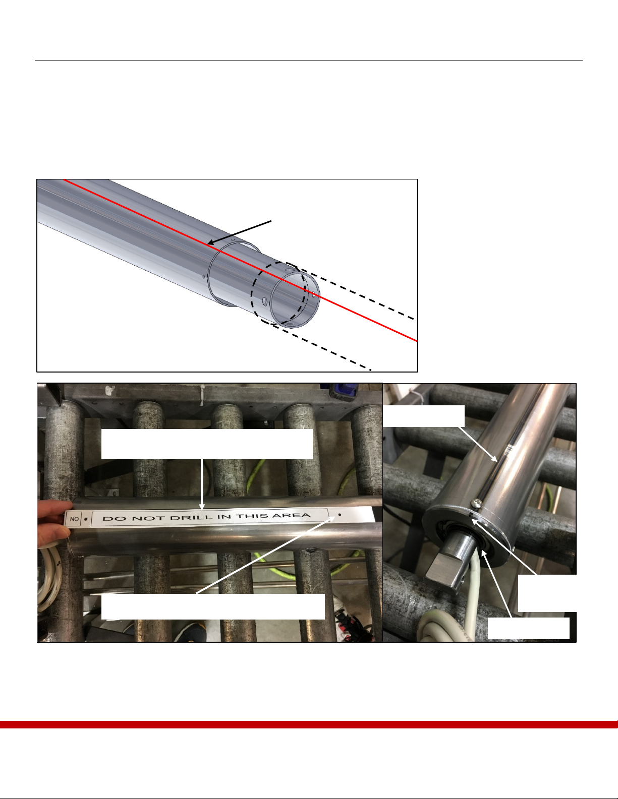
Section 5 – Preparing the Tubing ........................................................................................................................ 9
Section 6 – Curtain Attachment ........................................................................................................................10
Section 7 – Install the Curtain............................................................................................................................11
Section 8 – Attach the Bottom Bar....................................................................................................................12
8.1 – Attach the Roller Bracket ......................................................................................................................... 15
Section 9 – Attach the Side Guides ...................................................................................................................16
9.1 – Attach Up-Limit Stops ............................................................................................................................. 17
Section 10 – Cover Attachment.........................................................................................................................18
10.1 – Front Cover Attachment......................................................................................................................... 18
10.2 – Bottom Cover Attachment ..................................................................................................................... 18
Section 11 – Electrical Connections..................................................................................................................19
11.1 – 120VAC Connections ............................................................................................................................ 19
11.2 – Curtain Wiring........................................................................................................................................ 20
11.3 – Initiating Device Circuit......................................................................................................................... 20
11.4 – Optional Keyed Test Deploy Switch...................................................................................................... 20
11.5 – Optional Door Activation Switches ....................................................................................................... 21
11.6 – Optional SRS/Edge Sensor Curtain Switches ........................................................................................ 21
Section 12 – System Testing..............................................................................................................................22
12.1 – Calibration.............................................................................................................................................. 22
12.2 – System Test ............................................................................................................................................ 22
12.3 – Test Optional Keyed Switch .................................................................................................................. 22
12.4 – Test Optional Door Activation/Screen Rewind Switches...................................................................... 23
12.5 – Batteries.................................................................................................................................................. 23
Section 13 – Troubleshooting ............................................................................................................................24
13.1 – Contact Smoke Guard ............................................................................................................................ 25
Section 14 – Glossary .........................................................................................................................................26

3
Section 1 – System overview
The Model 2100 Smoke and Fire Curtain (M2100) is a motorized smoke and fire protection system housed in
the ceiling of a building. The system uses one motor to lower a specialized curtain into a strategic location.
When not in use the M2100 is retracted into a housing unit which maintains the aesthetic of the facility it is
installed in.
1.1 – Major Components
Figure 1– The Model 2100 Fire and Smoke Curtain.
A – M2100 Housing: The Housing contains the motor, Curtain, and other hardware essential to the function of
the Unit.
B – Side Guides: The Side Guides provide a track that enables the curtain to seal properly.
C – Curtain: The M2100 utilizes special smoke and fire protection Curtain material designed for your
application.
D – Bottom Bar Assembly: The Bottom Bar assembly provides a seal across the floor and weight to help the
Curtain function.
A
B
C
D

4
Section 2 – Main Controller and Conduit Routing
The Main Controller serves as housing for batteries, control switches, status LEDs and system control switches
which can be used to put the unit into different operating modes.
A – Low Voltage Power Block: The low voltage power block is the terminal location for most of the
systems on the M2100 including optional features.
B – High Voltage Power Block: The high voltage power block is the main input point for the M2100
power system.
C – PCA: The Printed Circuit Assembly (PCA) controls the normal operation of the M2100.
D – Status LEDs and Test Switch: The status LEDs indicate normal operation and errors on the
M2100. These lights can be used for troubleshooting the system and verifying certain conditions. The
system test microswitch is also found on the LED board.
E – Batteries: The batteries provide emergency power to the M2100, enabling it to deploy in the event
of primary power loss.
F – Power Switch: The power switch is used to turn the M2100 Main Controller on and off.
A
B
C
D
E
Figure 2– The M2100 Main Controller as seen from the exterior and interior.
F

5
2.1 – Optional Wireless Jogger
As an installation aid, Smoke Guard offers an optional wireless jogger device that provides remote control and
positioning of the curtain.
Once the controller is installed and all system wiring has been completed, the jogger can be connected as
described below:
Step 1 – Power off the Controller and disconnect the batteries.
Step 2 – Remove connector at PCA J3 (white, 10-pin) and insert jogger connector at this position. Connect
jogger red wire to terminal “10. +24VDC” and jogger black wire to terminal “4. COMMON” (system
wire “4” at this terminal can temporarily be stowed unconnected.)
Step 3 –Turn on Controller power and the system automatically enters jog mode within a few seconds. Green
LED will blink while in jog mode.
WARNING: Be sure the Controller is powered down before making connections.
Operation –The curtain position can now be controlled by up/down toggle switch on the transmitter. The
curtain braking action can be adjusted by pressing the BRAKE+ and BRAKE- buttons on the jogger
until the curtain remains stationary. The yellow LED will illuminate to indicate the braking action is
active. Simultaneously pressing both BRAKE+ and BRAKE- will cancel the braking action, the yellow
LED will turn off.
NOTE: Contact Smoke Guard for additional details on the wireless jogger.
2.2 – Checklist
To help keep track of the installation process and ensure that the M2100 is correctly installed, utilize the check
boxes that verify certain critical steps have been completed. A full checklist sheet is available in the appendix.
This is an example of how checklist items will appear throughout the installation.

6
Section 3 – Main Controller Installation
It is strongly recommended to maintain easy access and a line of sight from the control system to the M2100
Curtain. Remote installations make communication difficult during installation and servicing. An optimal
location to place the Main Controller is above removable ceiling tiles adjacent to the Curtain with a dedicated
access panel.
WARNING: The Main Controller must be within 30 conduit feet of the unit.
NOTE: This product is intended to be installed in accordance with the National Electric Code NFPA
105, National Alarm Code NFPA 105 and within the limits of the authority having jurisdiction.
Consult with site GC/electrician to identify Main Controller location. Reference your Installation
Layout Sheets to determine conduit routing paths. Requirements:
•Main Controller must be within 30 conduit feet of the Main Junction Box mounting location.
•1” conduit is routed between the Main Controller low voltage compartment and Main Junction
Box.
•½” conduit is routed to the Main Controller high voltage compartment to supply 120VAC.
•A 120VAC service disconnect is required at the Main Controller.
NOTE: Only low voltage DC is run between the Main Controller and Main Junction Box.
Consult with site GC/electrician to coordinate routing of conduit between Main Controller low voltage
compartment and initiating device (smoke detector or fire alarm). Requirements:
•½” conduit is required between initiating device and Main Controller low voltage compartment.
•Two 18 or 20 AWG stranded wires labeled 14 and 15 between initiating device and Main
Controller low voltage compartment.
NOTE: Wires 14 and 15 are connected to the Normally Open contacts of the initiating device in parallel
with the Smoke Guard EOL-Diode.
Consult with site GC/electrician to identify optional Wall Switch and/or Door Activation Switches.
Reference your Installation Layout Sheets to determine conduit routing paths and number of circuits.
Requirements:
•½” conduit is required between Wall Switch box and Main Controller low voltage compartment.
•Two 18 or 20 AWG stranded wires labeled 16 and 17 between Wall Switch box and Main
Controller low voltage compartment.
•½” conduit is required between Door Activation Switch box(es) and Main Controller low voltage
compartment.
•Two 18 or 20 AWG stranded wires for each switch between Door Activation Switch box(es) and
Main Controller low voltage compartment. First switch labeled 11 and 13, second switch labeled
12 and 13.
oIf using the optional Illuminated Door Activations Switches include an additional 18 or
20 AWG stranded wire for each switch labeled +24VDC.
•Single gang box.

7
Section 4 – Housing Installation
The Housing is the metal box in which all the M2100 hardware is installed. The Housing allows the unit to be
installed into a header or other worksite.
The tubular motor for the M2100 unit is located on one side of the curtain assembly. Determine which side
contains the tubular motor. The curtain must unroll from the back of the housing.
NOTE: Units 9ft in length or shorter will have a single housing section and will be shipped with the curtain
assembly pre-assembled inside the housing. Large units will have multiple housing sections that will
be assembled on-site. The curtain assembly for large units will also take place on-site.
Step 1 – Verify the installation
site. Position Housing so
that it rests on the rear of
the housing.
Step 2 – Remove the Front Cover
and Curtain Assembly
components.
Step 3 – For large units, join the
housing sections
together using the
provided joiner plates.
See Figure 4.
Step 4 – Lift the Housing into
place.
Front, right side of unit shown
Rear
Side
Simulated
header
Half of joiner plate
Pre-installed in Housing.
Top
Front
Rear
Figure 3 – Back Mounted M2100.
Figure 4– An angle plate inserted halfway into the M2100 Housing.

8
Step 5 – Anchor the M2100 Housing sections into place with a #12 self-drilling screw through the mounting
bracket located on the rear panel of the Housing. If your installation is being mounted to a ceiling, the
brackets will be located on the top panel of the Housing.
Anchor Housing into place with #12 self-drilling screws through the rear or top of the Housing
depending on mounting.
NOTE: Consult your architectural drawings to verify anchors specific to your installation site and local
construction requirements.
Figure 5– This shows the location of the End Bracket in the Housing.
WARNING: It is important that the motor wires do not become entangled with the moving parts of the Curtain
Assembly. Zip tie the wires securely to the bracket to keep the wires away from the curtain tabs.
Step 6– Attach fasteners appropriate for the mounting surface at ~3 foot intervals along the remainder of the
housing. Refer to your architectural drawings to determine the appropriate fasteners
Step 7– For units with a Screen Rewind Switch and/or Edge Sensor, use the included clamps to mount the ½”
conduit to the upper rear of the housing per Figure 5.
Step 8 – Install one of the included snap in-hole plugs in the hole at the center of each housing endplate.
Motor wire routing
Zip tie wires to
protect
During installation
Screen Rewind Switch/Edge
Sensor wire conduit

9
Section 5 – Preparing the Tubing
NOTE: For units narrower than 9ft, skip to step 5. If your curtain is mounted from the factory, skip to Section
7.
The Curtain must be attached to the Curtain Tube of the M2100 before it can be installed into the housing.
Step 1 – Locate the outer ends of the Curtain Tube Sections; one will contain the motor and the other will
contain the non-motor mounting shaft. The coupler joins the two opposite sides.
Figure 6– Aligning and joining the
pieces of curtain barrel.
Step 2 – Slide the longer section of tube over the coupler.
Step 3 – Locate the welded seam on the tubing. See Figure 7 for an example. Align the seams of the two pieces.
Welded seam
Motor wiring
Mark this
face
Welded seam located under metal band
Safe to drill and rivet in this location only.
Align the tubes so that the welded seams are
in the same location.
Figure 7– (LEFT) The metal band has a warning label to prevent damage to the motor. (RIGHT) The welded seam is used to align
tubing.

10
Section 6 – Curtain Attachment
Step 4 – Drill and rivet the non-coupler section to the coupler to complete the tube assembly.
WARNING: Do not drill in any area not identified in Figure 6 as safe. Failure to do so may cause permanent
damage to the motor.
Step 5 – Mark the side of the tubing at the weld seam location seen in Figure 7 to aid in Curtain assembly in
upcoming steps.
Step 6 – Identify the top of the Curtain (use the logo to aid in orientation) and line the top seam of the Curtain
along the welded seam. The Front of the Curtain should be facing towards the tube as it rolls up.
NOTE: The Front of the curtain is identified by sewing seams on the Curtain. The front of the Curtain is the
side with the smooth seams. Some, but not all M2100 units will have a logo stamped on both sides, so
the seams should be used to identify the Curtain.
Step 7 – Align the top of the Curtain with the weld seam and secure it to the Curtain Tube with the included
tape. Roll the Curtain around the tubing once as shown in Figure 8. Lay the metal band on the curtain
aligned with the weld seam.
Step 8 – Using the mark from step 5, carefully drill holes through the strap, 2 layers of Curtain, and tube with a
#30 bit (0.125”-0.135”). Space these holes ~12” apart and take care to avoid the motor while drilling.
Drill holes in safe
locations appropriate for
1/8” pop rivets.
Step 9 – Insert rivets through the
holes to fasten the strap
and Curtain to the
tubing. See Figure 8 for
reference on this
process.
Pop rivet the Curtain to
the tubing.
Step 10 – Roll the Curtain
completely around the
tube. Do not allow more
than ¼” of telescoping
on either side of the
tube.
Figure 8 – Example of the tubing assembly as seen in this side profile.
Rivets must go through band and
2 layers of Curtain into the tubing.
Welded seam
Curtain
Tube

11
Section 7 – Install the Curtain
Step 1 – Verify the Curtain assembly will fit into the Curtain support brackets with at least ¼” of space between
the Curtain and the Housing.
Verify Curtain assembly will fit into Housing with ¼” gap on the sides.
Step 2– Install the Curtain assembly into the brackets at both sides of the Housing.
NOTE: No fasteners are required to hold the Curtain assembly in the brackets.
Step 3– Pull the motor wire through either the hole on the top or endplate of the housing and secure in place
with the included cable clamp. Plug the other hole with one of the included snap-in hole plugs.
Step 4– For units with a Screen Rewind Switch and/or Edge Sensor, route the cable from the non-motor end of
the curtain tube through the previously mounted conduit. Secure this wiring and the motor wiring
away from the curtain tabs to avoid entanglement. See Figure 4 for an example.
Figure 9 – Mount the tubing into the housing and place each end into the Curtain Support Brackets.
Curtain Support Brackets

12
Section 8 – Attach the Bottom Bar
Step 1 – Pull the fully deployed curtain taught to the ground.
Step 2 – The Bottom Bar assembly consists of half triangular pieces that make up the front and back and an
internal Clamp Rod with retainers on each end.
Step 3 – Layout the Bottom Bar assembly per the drawing under the unit and center it under the Curtain with 2”
of the curtain retainers exposed at each end. See Figure 10. Wrap the Curtain around the Clamp Rod,
leaving at least 1-1/2” of Curtain overlap.
Step 4 – Bring the two halves of the Bottom Bar assembly around the Clamp Rod so that the top of the
assembly halves lines up with the 1-1/2” Curtain overlap. Temporarily clamp the Bottom Bar halves
together to hold the assembly in place. See Figures 10 & 11.
Bring the two halves of the assembly around the clamp rod.
WARNING: Do not connect the components of the Bottom Bar Assembly without the Curtain. The Curtain
must be connected to the assembly.
Figure 10 – Clamp the bottom bar assembly in place in this
position.
NOTE: Curtain not shown. Do not fasten
Bottom Bar without Curtain.

13
Step 5 – With the Bottom Bar assembly securely on the floor, pull the Curtain through the Bottom Bar
assembly to remove any slack from the Curtain.
NOTE: Pulling the overlapped section of Curtain to remove slack will also seat the Clamp Rod properly into
place inside the Bottom Bar assembly. See Figure 11.
Step 5 – Ensure the Curtain is free of slack and the Bottom Bar assembly is properly set up (see Figure 11).
Fasten the assembly together using the supplied 1/8” steel rivets (necessary for fire-rated curtains) or
low-profile self-drilling screws.
NOTE: If self-drilling screws are used in Step 5, it will be necessary to grind off the back side to ensure there is
no more than 1/8” protrusion.
Step 6 – Using the supplied thread sew the Curtain to the Bottom Bar Retainers by threading it together through
the holes at the edges of the Bottom Bar assembly. See Figure 12 for thread routing.
Figure 11– (LEFT) The arrangement of components. (RIGHT) The assembly when it is fastened together. Note the
Curtain is pulled tight around the rod which is pulled against the top of the triangle.
Cut excess
Curtain
protruding out
of the Bottom
Bar assembly
once final
adjustments are
complete.
Location for additional ballast.

14
Figure 12– Sew the Curtain in a circular pattern as shown in this image. The specialized thread should enter from one side, pass
under the Curtain rod and then back through the Curtain.
NOTE: The sides of the Curtain cannot be riveted due to Side Guide clearance. They must be sewn to ensure
smooth operation.
Step 7 – Trim the excess Curtain protruding from the top of the Bottom Bar assembly.
Step 8 – If necessary, slide additonal ballast to the Bottom Bar assembly by inserting an additional steel rod into
the open triangle cavity as seen in Figue 11. The additional weight ensures that the Curtain will fall to
the floor in the event of AC and backup battery power loss.
Sew each side of the Curtain to the Bottom bar assembly using the supplied thread.

15
8.1 – Attach the Roller Bracket
NOTE: Roller Bracket is only required on very wide units. Reference layout drawings to determine if one is
necessary.
Step 1 – Roll the Curtain tightly into the housing. Do not allow more than 1/8” of telescoping on either side.
Step 2 – Zip tie or tape the Curtain to temporarily keep it suspended in the Housing.
Step 3 – Position the roller bracket as close as possible to the center of the Curtain so that the center most seam
of the Curtain will be supported.
Step 4 – Slots in the bottom of the Roller Bracket allow you to fit a drill up to the top of the housing.
Step 5 – Use two fasteners to anchor the Roller Bracket through the cutouts provided.
Roller Bracket supports the
Curtain inside the Housing
Figure 13 – The Roller Bracket rests under the Curtain Assembly and supports it in the Housing.

16
Section 9 – Attach the Side Guides
The Side Guides are shipped in multiple parts and must be assembled at the installation site.
Step 1 – Measure the distance from the finished floor to the bottom of the Housing on each side.
Step 2 – If necessary, cut the
bottom of the pre-
assembled Guides to
length so the top of
the Guide is flush
with the bottom of
the Housing.
WARNING: Do not cut the
top of the Side
Guides (the top is
identified by bends
in the assembly).
Step 3 – Raise the Guides
into place.
Step 4 – There are two means of attaching the M2100 Guides.
IF ATTACHING TO JAMB OR INTO
POCKET: Insert a drill extension with a
backing-appropriate anchor through the
slot at the top of the Guide, lower the drill
to the first pre-drilled hole and anchor into
the wall surface.
IF ATTACHING TO FACE OF AN
OPENING: Drill out the hole on the
outside face of each Guide to 9/16”. Insert
a drill extension with a backing-
appropriate anchor through the holes on
and anchor into the wall surface. Cover the
holes with the included 9/16” plugs.
Bottom Bar assembly
Side Guide assembly
cross-section
Figure 14 – This cross section shows how the Curtain and Bottom Bar assembly will interact.
Jamb Mount
Face Mount
Figure 15 – Common configurations for Side Guide installation. The Side
Guide assemblies have mounting holes for both configurations.

17
Anchor the Side Guides into position.
Step 5 – Insert the Curtain tabs down into the side guide slots. See Figure 14.
Step 6 – Pull the Curtain down the guides until all of the Curtain material is unwound from the roll.
9.1 – Attach Up-Limit Stops
Step 1 – If the Curtain in your installation must seat below the
Housing rather than flush with the bottom of it, attach the optional
Up Limit Stops to the side guide. These stops will line up with the
Bottom Bar assembly and stop the Curtain at the correct point
during calibration. There must be 2 Up Limit Stops on each side of
the M2100 for a total of 4. See Figure 15 for an image of the Up-
Limit Stops.
Figure 15– The Up-Limit Stops can be
installed at any length along the Side Guides
to enable the Curtain to calibrate to a desired
height.
Up-Limit
Stops

18
Section 10 – Cover Attachment
10.1 – Front Cover Attachment
Step 1 – (For longer units) align cover sections flush at the edges and cover with a joiner plate.
Step 2 – (For longer units) pop-rivet the joiner plate to the section covers.
Step 3 – Lift the front covers to the Housing and attach using the self-drilling screws provided.
Attach the front cover(s).
10.2 – Bottom Cover Attachment
Step 1 – Align the bottom cover panel(s) so that the angled section aligns with the front cover’s angled bottom.
Step 2 – Screw the bottom cover panel(s) to the Housing using the self-drilling screws provided.
Attach the bottom cover(s).
NOTE: Maintenance or repair of the M2100 can occasionally require removal of the Curtain Barrel assembly,
which also requires removal of the bottom cover panel(s). It is recommended that access panels or other
methods of access be included at install.

19
Section 11 – Electrical Connections
This section covers the wiring of the M2100 systems. Depending on your installation, some steps may
not apply.
NOTE: This product is intended to be installed in accordance with the National Electric Code NFPA
80, National Alarm Code NFPA 80 and within the limits of the authority having jurisdiction.
11.1 – 120VAC Connections
Step 1 – Ensure 120VAC wiring has been installed at the Controller high voltage compartment and that
the service disconnect is open.
System Layout
Figure 16 – The wiring layout for the M2100.

20
11.2 – Curtain Wiring
NOTE: The following procedures are also applicable to Dual system controllers. Ensure wiring from
each curtain is properly grouped to either SYSTEM #1 or SYSTEM #2 terminal blocks.
Step 2 – At the Controller low voltage compartment connect each wire as follows:
Wire
Terminal Description
1 / WHT / BLU
1. MOTOR +
2 / GRY / BRN
2. MOTOR –
3 / BRN / BLK
3. SENSOR POWER
4 / GRN / RED
4. COMMON
5 / YEL / YEL
5. SENSOR SIGNAL
NOTE: Exercise care in making all terminations. Incorrect wiring can lead to permanent damage.
11.3 – Initiating Device Circuit
Step 1 – Ensure that wires 14 and 15 have been installed at the Normally Open contacts of the initiating
device. The Smoke Guard EOL-Diode should be connected in parallel with these contacts,
order of diode wires does not matter.
Step 2 – At the Controller low voltage compartment connect wires as follows:
NOTE: If it is not possible to perform this step at this time connect the Smoke Guard EOL-Diode
directly into terminals 14 and 15 to avoid system fault during subsequent testing.
11.4 – Optional Keyed Test Deploy Switch
Step 1 – Ensure that wires 16 and 17 have been installed at the remote key-switch, order of wires does
Motor Wire
Wire to
Controller
Optional Screen
Switch/Sensing
Edge Cable 38554
Wire to
Controller
1 / WHT / BLU
1
BLK
6
2 / GRY / BRN
2
RED
7
3 / BRN / BLK
3
WHT
13
4 / GRN / RED
4
5 / YEL / YEL
5
Wire
Terminal Description
14
14. SMOKE DET/FIRE ALARM +
15
15. SMOKE DET/FIRE ALARM -
Table of contents
Popular Firefighting Equipment manuals by other brands

Tyco
Tyco EC-25 quick start guide

ENFORCER
ENFORCER 30 Operation and maintenance manual

TFT
TFT Extend-A-Gun VP INSTRUCTION FOR SAFE INSTALLATION, OPERATION, AND MAINTENANCE

Amerex
Amerex 450 Installation, operating & servicing instructions

Tyco
Tyco EC-11 Series quick guide

Task Force Tips
Task Force Tips EDUCTOR 125 Series Instructions for installation, operation and maintenance