TFP802
Page 5 of 6
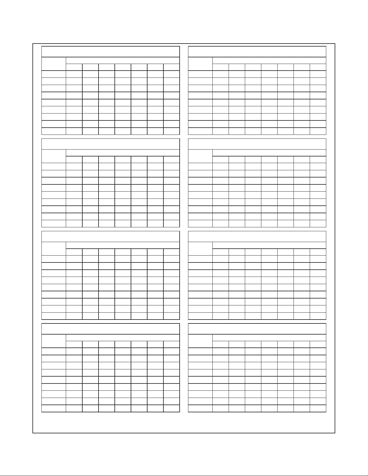
MAXIMUM AXIAL DISTANCE FOR 65° SPRAY ANGLE
IN METERS
FIXED
ANGLE
ORIFICE SIZE
16 18 21 24 28 32 34
0° 3,2 3,8 4,0 4,0 4,4 4,6 4,7
30° 2,5 3,3 3,3 3,6 3,8 4,1 4,2
45° 2,2 3,0 3,0 3,4 3,5 3,8 3,9
60° 2,0 2,8 2,9 3,3 3,4 3,6 3,8
90° 1,8 2,6 2,7 3,1 3,2 3,3 3,5
120° 1,8 2,3 2,3 2,3 2,5 2,7 2,9
135° 1,7 1,8 1,9 2,0 2,1 2,4 2,6
150° 1,6 1,7 1,7 1,9 1,9 2,2 2,3
180° 1,5 1,5 1,5 1,7 1,8 2,0 2,1
MAXIMUM AXIAL DISTANCE FOR 80° SPRAY ANGLE
IN METERS
FIXED
ANGLE
ORIFICE SIZE
16 18 21 24 28 32 34
0° 2,7 3,2 3,4 3,7 4,0 4,3 4,3
30° 2,2 2,5 2,7 3,2 3,5 3,7 3,7
45° 1,9 2,3 2,4 3,1 3,2 3,4 3,4
60° 1,7 2,1 2,3 3,0 3,1 3,3 3,3
90° 1,5 1,8 2,1 2,8 2,9 3,0 3,0
120° 1,4 1,4 1,8 2,0 2,2 2,1 2,4
135° 1,3 1,4 1,5 1,7 1,8 1,9 2,1
150° 1,2 1,2 1,4 1,5 1,7 1,7 1,8
180° 1,1 1,1 1,2 1,4 1,4 1,6 1,7
MAXIMUM AXIAL DISTANCE FOR 95° SPRAY ANGLE
IN METERS
FIXED
ANGLE
ORIFICE SIZE
16 18 21 24 28 32 34
0° 2,1 2,4 2,9 3,2 3,4 3,7 3,8
30° 1,8 2,0 2,4 3,0 3,2 3,3 3,4
45° 1,6 1,9 2,1 2,9 3,0 3 ,1 3,1
60° 1,4 1,8 2,1 2,8 2,9 3,0 3,0
90° 1,2 1,5 2,0 2,5 2,6 2,7 2,7
120° 1,1 1,1 1,5 1,6 1,9 1,8 2,0
135° 1,0 1,1 1,2 1,4 1,6 1,6 1,7
150° 0,9 0,9 1,1 1,2 1,4 1,4 1,4
180° 0,9 0,9 1,1 1,1 1,2 1,3 1,4
MAXIMUM AXIAL DISTANCE FOR 110° SPRAY ANGLE
IN METERS
FIXED
ANGLE
ORIFICE SIZE
16 18 21 24 28 32 34
0° 1,8 2,1 2,7 2,9 3,4 3,4 3,5
30° 1,6 1,9 2,2 2,7 2,9 3,0 3,0
45° 1,4 1,8 2,0 2,6 2,7 2,7 2,8
60° 1,3 1,7 1,9 2,5 2,6 2,6 2,7
90° 1,1 1,4 1,8 2,3 2,3 2,3 2,4
120° 0,8 1,0 1,4 1,4 1,7 1,7 1,7
135° 0,8 0,8 1,1 1,1 1,4 1,4 1,4
150° 0,7 0,8 0,9 1,0 1,1 1,1 1,3
180° 0,7 0,7 0,8 0,9 1,1 1,1 1,1
MAXIMUM AXIAL DISTANCE FOR 125° SPRAY ANGLE
IN METERS
FIXED
ANGLE
ORIFICE SIZE
16 18 21 24 28 32 34
0° 1,4 1,5 2,0 2,4 3,0 3 ,1 3,2
30° 1,1 1,1 1,9 2,1 2,6 2,6 2,7
45° 0,9 1,1 1,8 1,8 2,4 2,3 2,5
60° 0,8 0,9 1,7 1,8 2,2 2,2 2,4
90° 0,6 0,8 1,4 1,5 1,8 1,8 2,0
120° 0,5 0,7 1,0 1,0 1,1 1,1 1,4
135° 0,5 0,5 0,8 0,8 1,0 1,0 1,1
150° 0,5 0,5 0,6 0,7 0,8 0,8 1,1
180° 0,4 0,4 0,5 0,6 0,7 0,8 1,0
MAXIMUM AXIAL DISTANCE FOR 140° SPRAY ANGLE
IN METERS
FIXED
ANGLE
ORIFICE SIZE
16 18 21 24 28 32 34
0° 1,2 1,4 1,8 2,0 2,4 2,4 2,4
30° 1,0 1,1 1,7 1,7 1,9 2,1 2,1
45° 0,8 0,8 1,5 1,5 1,7 2,0 2,0
60° 0,7 0,8 1,4 1,4 1,6 1,7 1,8
90° 0,5 0,7 1,2 1,2 1,4 1,4 1,5
120° 0,5 0,5 0,7 0,8 0,8 0,9 1,1
135° 0,4 0,5 0,5 0,5 0,6 0,8 0,8
150° 0,4 0,4 0,5 0,5 0,5 0,7 0,8
180° 0,3 0,3 0,4 0,4 0,5 0,6 0,7
MAXIMUM AXIAL DISTANCE FOR 160° SPRAY ANGLE
IN METERS
FIXED
ANGLE
ORIFICE SIZE
16 18 21 24 28 32 34
0° 1,1 1,1 1,4 1,5 1,8 2,1 2,1
30° 0,8 0,9 1,3 1,4 1,5 1,8 1,9
45° 0,7 0,8 1,1 1,2 1,4 1,6 1,7
60° 0,5 0,7 1,1 1,1 1,1 1,4 1,6
90° 0,4 0,5 0,9 1,0 0,7 1,1 1,3
120° 0,3 0,4 0,5 0,6 0,5 0,7 0,8
135° 0,3 0,3 0,4 0,4 0,5 0,5 0,6
150° 0,2 0,2 0,3 0,3 0,5 0,5 0,5
180° 0,2 0,2 0,2 0,2 0,5 0,5 0,5
MAXIMUM AXIAL DISTANCE FOR 180° SPRAY ANGLE
IN METERS
FIXED
ANGLE
ORIFICE SIZE
16 18 21 24 28 32 34
0° 0,8 0,9 1,1 1,1 1,2 1,8 1,8
30° 0,7 0,7 1,1 1,1 1,1 1,5 1,5
45° 0,5 0,6 1,0 1,0 1,1 1,3 1,3
60° 0,5 0,5 0,8 0,8 1,0 1,1 1,1
90° 0,3 0,5 0,6 0,6 0,8 0,9 0,9
120° 0,2 0,3 0,3 0,3 0,5 0,5 0,5
135° 0,2 0,2 0,2 0,2 0,4 0,4 0,4
150° 0,2 0,2 0,2 0,2 0,3 0,3 0,3
180° 0,2 0,2 0,2 0,2 0,2 0,2 0,2
TABLE D
MAXIMUM AXIAL DISTANCE BETWEEN NOZZLE TIP AND
PLANE-OF-PROTECTION FOR EXPOSURE PROTECTION — METERS