CSZ Z-Plus User manual

Page 1-C
Z-Plus Test Chamber
Quick Start Guide
Thank you for purchasing your Cincinnati Sub-Zero environmental test chamber.
Please use this ZP Quick Start Guide and Unit startup checklist (IF0230) as an overview for your chamber
installation and operation. For all details regarding your chamber, please read the user manual in its entirety. This
reference guide does NOT replace the user manual.
Please refer to the Installation, Operation, Maintenance, and Troubleshooting/Q&A sections of the manual for
commonly asked questions.

Page 2-C
1. Transporting your Unit
1.1. Inspect all equipment for damage that may have occurred during shipment. Contact Cincinnati Sub-Zero
immediately if any shipping damage is noticed.
1.2. A forklift should be used to remove the unit from the skid.
1.3. The unit is to be lifted from the side as shown in the illustration below:
1.4. Forks should extend past the other side of the chamber to prevent damage.
1.5. The rear of the chamber is heavier than the front, use caution when lifting.
1.6. The chamber should be 2”-3” off the floor when transporting.
1.7. The unit is also equipped with casters and can be moved manually once removed from the skid.
2. Getting to know your Chamber
2.1. General Layout

Page 3-C
2.2. Model Number Break Down: The serial number and model number can be found on the data tag.
3. Select your chamber’s location
3.1. The location must be smooth and level with a maximum slope in any direction of 1/8” (3 mm) x 10’ (3 m).
3.2. For proper ventilation a minimum clearance of 12” (31 cm) must be maintained around the sides of the
chamber and 30” (70 cm) of clearance at the back of the chamber.It is recommended to maintain a 36”
(91 cm) clearance around the chamber for ease of service access.

Page 4-C
3.3. Each unit will vary based on model but can give off up to 63,000 BTU/Hr. (18.46 KW) of heat into the
room it is installed in. This heat must be removed to maintain the chamber environment specs.
3.4. The chamber must be installed in an environment between 65°F (18.3°C) and 85°F (29.4°C) with a
maximum humidity of 95% at a maximum elevation of 7,000 ft. (2133.6 m) for proper operation.
3.5. The unit can be leveled by adjusting the leveling feet using a 1/2” (13 mm) open end wrench.
4. Connect Necessary Utilities
4.1. Connect supply power to the chamber through the 1-1/4” EMT conduit to TB-1 on the electrical sub-
panel, reference data tag for proper power requirements.All electrical connections and adjustments
should be performed by a licensed electrician.
4.2. Connect humidity supply water using a 1/4” plastic water hose. (optional)
4.3. Route or connect 1/2" chamber drain to an open air drainage system.
4.4. Connect Refrigeration Water (If applicable)
4.4.1. Review data tag for proper HP rating and find the proper connection size and flow rates below.
LOW TEMP HERMETIC & SEMI-HERMETIC
COMPRESSORS
LOW TEMP SCROLL COMPRESSORS
WATER
TEMPERATURE
85°F 75°F 65°F 55°F
WATER
TEMPERATURE
85°F 75°F 65°F 55°F
29°C 24°C 18°C 13°C
29°C 24°C 18°C 13°C
HP
Pipe Size
GPM
GPM
GPM
GPM
HP
Pipe Size
GPM
GPM
GPM
GPM
1
3/8”
3.3
2
1.4
1.1
2
1/2”
4.8
2.8
2
1.6
1.5
1/2”
4.8
2.8
2
1.6
3
1/2”
6.4
3.8
2.7
2.2
2
1/2”
8.9
5.2
3.8
3
3.5
1/2”
7.9
4.7
3.4
2.7
3
3/4”
11
6.5
4.7
3.8
5
3/4”
11
6.5
4.7
3.8
6
3/4”
20
11.8
8.5
6.8
6
3/4”
13.2
7.8
5.6
4.5
7.5
1”
23.8
14.1
10.1
8.1
7.5
3/4”
16.1
9.5
6.8
5.5
10
1”
34.2
20.2
14.5
11.6
10
1”
22.9
13.6
9.7
7.8
15
1-1/4"
44.4
26.2
18.8
15.1
13
1”
28.2
16.6
11.9
9.6
22
1-1/2”
53.7
31.7
22.8
18.3
15
1-1/2"
33.3
19.7
14.1
11.4
27
1-1/2”
67.7
40
28.7
23.1
30
2”
78.6
46.5
33.4
26.8
4.5. Connect 4” cuff pressure relief vent to ventilation system. (optional, but required on units with LN2 or
GN2 systems to eliminate the risk of asphyxiation)
4.6. Refer to user manual for communication connections and all other optional connections.
4.7. For ease of service it is recommended:
4.7.1. Utility connections should be flexible and at least 3’ (92 cm) in length.
4.7.2. Main power disconnect should be installed on incoming power.

Page 5-C
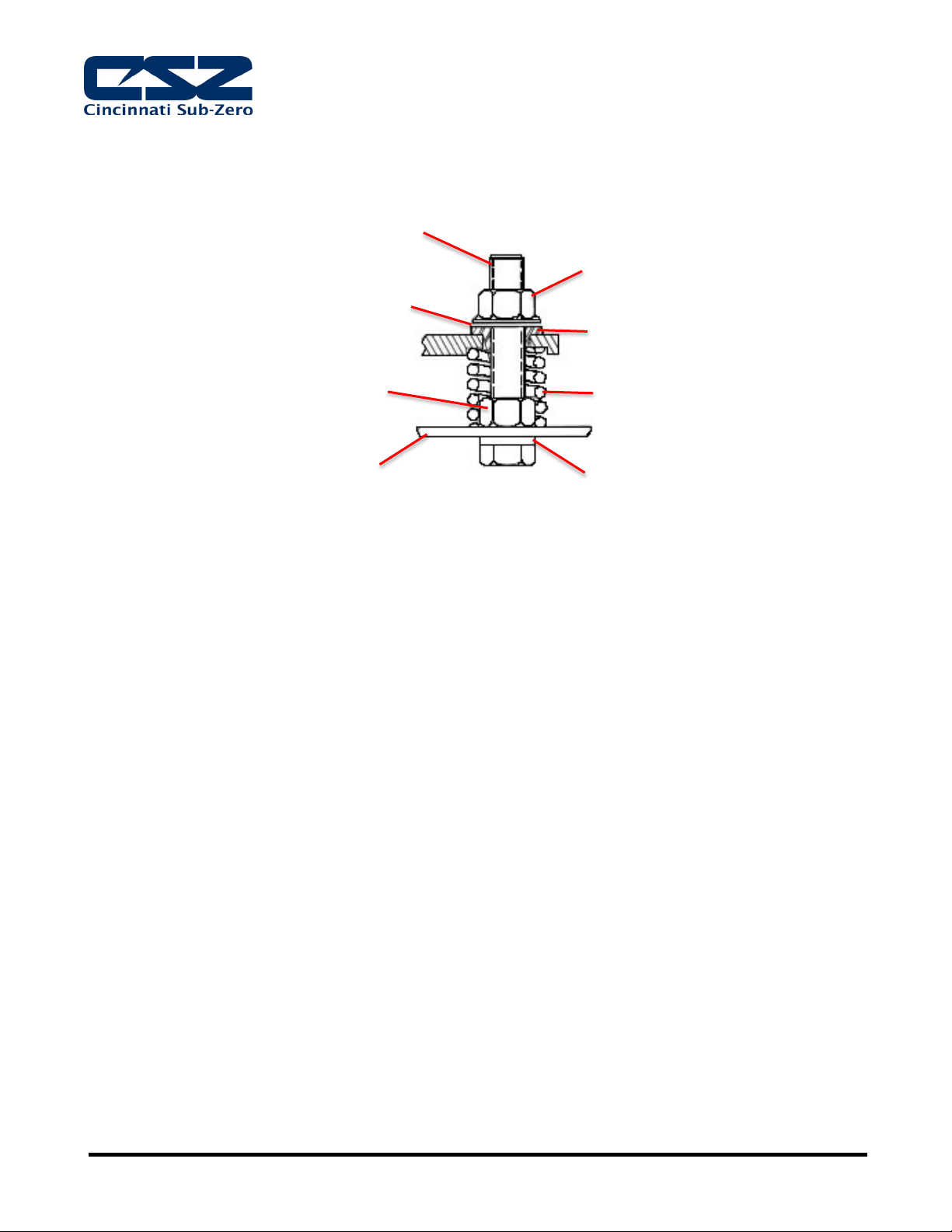
4.8. If unit is installed with Semi Hermetic Spring Mounted Compressors, follow these steps:
4.8.1. Loosen the upper nuts and washers until compressor floats on springs.
4.8.2. Discard the shipping spacers.
4.8.3. Allow 1/16 inch space between the upper mounting nut and rubber spacer. See Figure 4-2 below.
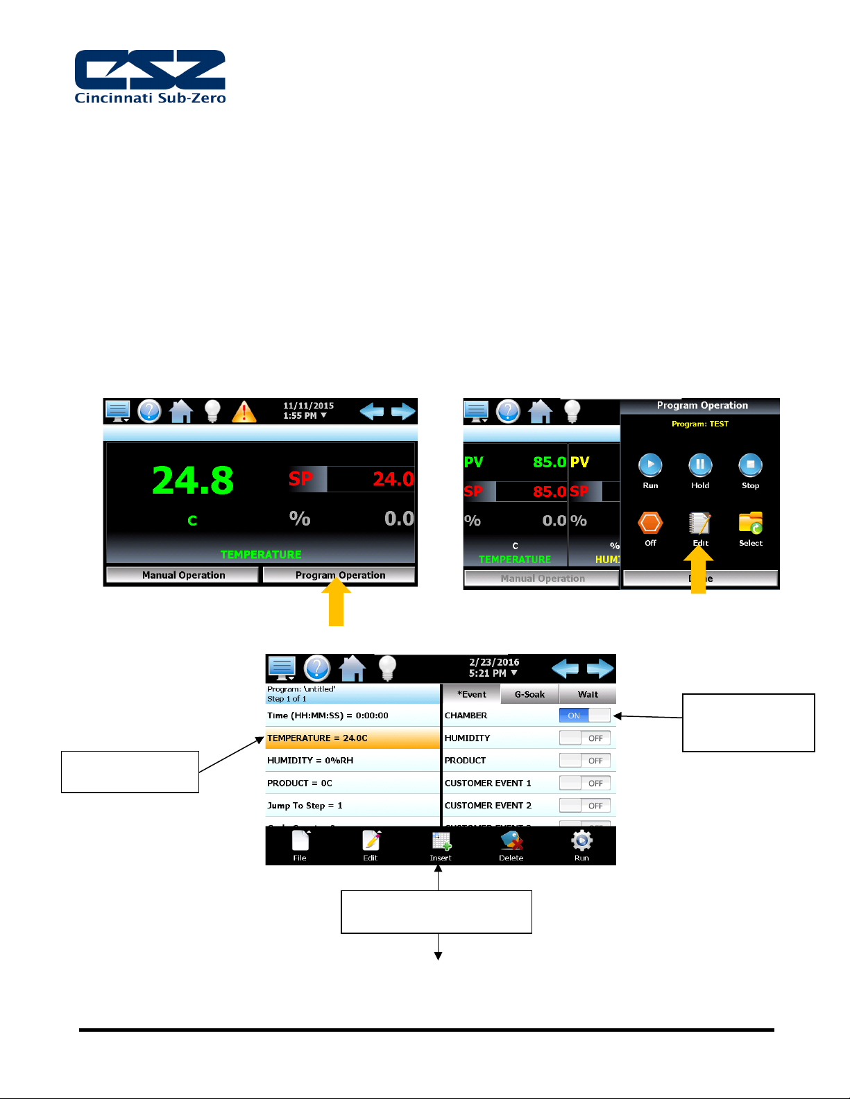
5. Unit Startup
5.1. The Installation Section in the ZP Manual (Page 55) should be
referenced for the detailed start up procedures.
5.2. The following must be performed prior to starting the unit:
5.2.1. Check the system pressures using the refrigeration system pressure gauges.
5.2.1.1. DO NOT START if the R-508B / R23 (System 2) static pressure is more than 30 PSI (2
bar(g)) lower than that specified on the data plate, contact the CSZ Service Department.
5.2.1.2. DO NOT START if the R-404A (System 1) or R-410A (Tundra) pressure is less than 100PSI
(6.9bar(g)), contact the CSZ Service Department.
5.2.2. Units with semi-hermetic compressors: loosen nuts holding them in place to allow the compressor
to float freely on the spring system.
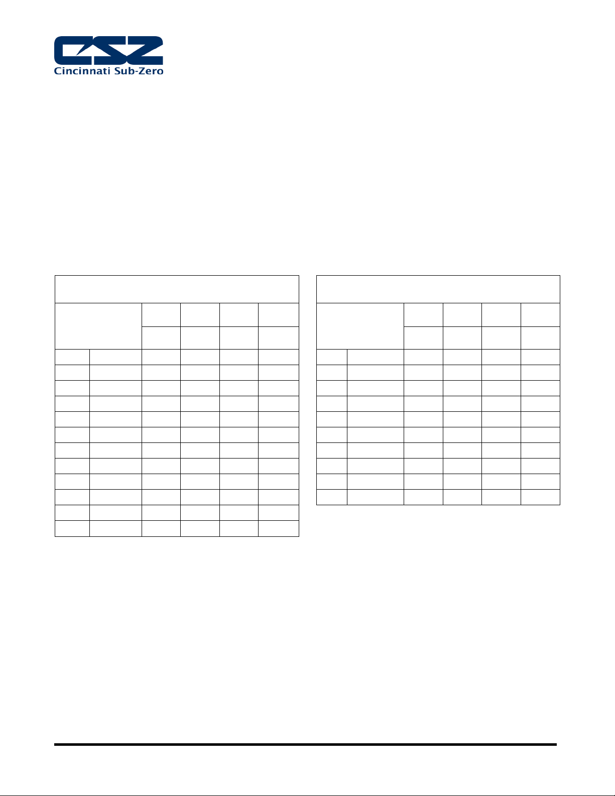
5.2.3. Water cooled unit supply flow rates are determined by the inlet water temperature, please see chart
in Section 4.4.1 for proper flow rates.
5.2.3.1. Open Loop Systems require a minimum supply pressure of 40 PSI (275 kPa) with a
maximum supply pressure of 60 PSI (515 kPa).
5.2.3.2. Closed Loop Systems require a minimum pressure differential (supply pressure minus return
pressure) 40 PSI (275 kPa) with a maximum supply pressure of 60 PSI (515 kPa).
5.2.3.3. Verify that the incoming water flow rate is adequate based on temperature.
5.3. Once power is applied the unit, it must sit for 4 hours prior to refrigeration operation to allow the
crankcase on the compressor to heat properly.
5.4. 3 Phase Scroll Compressors will run backwards if the power leads are installed incorrectly.
5.4.1. Correct Installation: The discharge pressure increases and the suction pressure decreases
5.4.2. Incorrect Installation: The discharge pressure decreases and the suction pressure increases.
Reverse any two power leads to correct the issue.
5.5. 10hp refrigeration systems and above are equipped with “Pumpdown”
5.5.1. “Pumpdown” protects System 1 compressor on start up by forcing refrigerant to the high side.
5.5.2. If supply power is off for more than 30 minutes the “Pumpdown Disabled” alarm will occur and the
chamber will not operate
5.5.3. “Pumpdown Disabled” will automatically clear after the power has been restored for more than 4
hours.
5.5.4. If power has been restored to the unit with-in 4 hours after the 30 minute off period the alarm can
be reset manually.
Mounting Nut
(Upper)
Rubber Spacer
Mounting Spring
Lockwasher
Mounting Base
Leave 1/16 inch space
after Installation
Mounting Stud
Mounting Nut
(Lower)

Page 6-C
6. EZT-570S Controller
NOTE: There will be a 15 second delay prior to complete system boot up
6.1. Controller Icons and Display
The menu icon will open the main menu for navigating to the different control and monitoring
screens. Menu items will dynamically appear providing available options based on the system area
the user is in, i.e., security, data logging, setup, etc.
The information (help) icon will display text based help associated with the current screen. Help is
available in 28 languages based on the user selection in the offline setup of section of the EZT-
570S.
The home icon will return the user to the main view from anywhere in the EZT-570S application.
The alarm icon will appear and flash when a new system alarm occurs. Pressing the alarm icon will
take the user directly to the alarm screen in order to view and/or reset the active alarm condition.
The light icon allows the user to turn the chamber light(s) on and off.
The left and right navigation arrows will appear on screens that provide additional information that
the user can scroll to such as the main view screen, real time trends or program entry screen in
order to cycle through each step of a ramp/soak program.
Compressors are equipped
with crankcase heaters. After
connecting the power, the unit
must sit 4 hours before start-up to
properly heat-up.
If your chamber is equipped with
pumpdown, main power should remain on at
all times. If power is removed for extended
periods of nonuse, do not reset pumpdown
after power is applied to the unit. Only silence
the alarm. Allow for the 4 hour warm-up
period prior to use or damage to the
compressor may result.
Icon Bar
Main
Display

Page 7-C
6.2. Configuration Settings
6.2.1. Select Menu Icon, settings and then navigation
6.2.1.1. Configure how you want to navigate your controller using drop-down window menu (similar to
previous CSZ controllers) or slide-navigation using icons like a smartphone. Setting may be
changed at any time.
6.3. Running Chamber Without a Profile
6.3.1. Touch the red “SP” box and enter a
temperature set-point.
6.3.2. Touch the “Manual Operation” to access the
on/off switches menu.
6.3.3. Touch the toggle switch next to “CHAMBER”
to toggle from “OFF” to “ON”.
6.3.4. Touch “Done” to close the “switches” menu
and set the changes made.
6.3.5. To set a relative humidity set-point follow the
above process using the grey “%” box and
the “HUMIDITY” toggle switch.
6.4. Using Guaranteed Soak (G-Soak) Event
6.4.1. The G-Soak selection for a profile is a tool that allows the user to guarantee timed soaks with-in
specified limits for the event selected.
6.4.2. The G-Soak selections are used to turn on the guaranteed soak option for one or more of the
control loops. To enable guaranteed soak for a loop, first press the ‘G-Soak’ button above the
event list view on the Program Entry screen. This will display the list of soak selections for each
loop of the chamber.
6.4.3. Press the on/off button for a loop to toggle the guaranteed soak selection on and off as desired.
When the guaranteed soak event for a loop is turned on, the program will automatically enter a
hold condition during the step if the loop’s PV deviates from its set point by more than the soak limit
setting for the loop as entered on the G-Soak Limits screen.
Guaranteed soak should not be used on ramping steps. The ramp rate will be affected if the
process variable deviates from the soak band because the program will be placed in hold. When
the program is in hold, the step length will be extended and the set points will no longer ramp at the
desired rate. Guaranteed soak should be used on soak steps to make sure that the process stays
at the desired set point, within the soak band, for the full time duration of the step.

Page 8-C
6.5. Using “Wait For” Event
6.5.1. The “wait” function is a powerful tool for pausing a program until a particular process variable
reaches a predefined set point. This differs from the guaranteed soak function by being a single
shot monitor. With the guaranteed soak, the process variable is monitored throughout the whole
step. If the process exceeds the upper or lower soak band, the program will pause until the process
returns to within the band. The wait for function puts the program in hold and “waits for” the
process to exceed a particular value that is set for the step. Once the process reaches this set
point value, the program will resume.
6.5.2. A program can also be set to wait for a digital input. This allows any of the eight optional digital
inputs to be selected. When the EZT-570S reaches the step, it will wait for the input to change
state before continuing the step.
6.5.3. To enable a wait condition in a step, first press the ‘Wait’ button above the event list view on the
Program Entry screen. This will display the list of available wait selections. Select the input to wait
for, and if a process variable is selected (Loop or monitor input) enter the set point for the wait.
This is the set point that the process variable must reach in order for the step to continue.
The set point entry for a wait step is critical for the “wait for” loop or monitor to operate correctly.
During the wait state, the selected process input must arrive at or cross the set point (Wait SP) in
order for the program to resume operation.
6.5.4. The monitor input and digital input selections are only available if the option is available on your
chamber. When using a digital input as a wait for selection, the digital input must be configured as
a “wait input”. If it is not configured as a “wait input”, the program will ignore the wait for selection
and continue through the step. See EZT Manual for more information.

Page 9-C
6.6. Running a Sample Profile
6.6.1. Below are screenshots and explanations (in consecutive order) of the sample profile listed below.
Example:
1. Run a test that starts at 24°C.
2. Ramp to 85°C in 5°C/min.
3. Soak at 85°C for one hour.
4. Ramp from 85°C to -40°C in 5°C/min.
5. Soak at -40°C for one hour. Repeat cycle for a total of five cycles.
6. Ramp back to 24°C.
7. Soak at 24°C for thirty minutes
8. Enter the last step without turning on events to end the profile.
6.6.2. Profile Entry Screens
6.6.2.1. To enter a new profile, select the “Program Operation” button then select “Edit”.
6.6.2.2. Step 1 – Specify starting point
Temp changed to
24°C
Chamber switch
turned to ON
position
The “Insert” feature is used to
add the next step

Page 10-C
6.6.2.3. Step 2 – Ramp to 85°C at 5°C/min
6.6.2.4. Step 3 – Soak at 85°C for 1 Hr.
6.6.2.5. Step 4 – Ramp to -40°C at 5°C/min
Temp set to 85°C
Ramp Rate set to
5°C/min
Time is automatically
calculated by the ramp rate
and temp set point
Time set to 1 Hr.
Temp set to -40°C
Ramp Rate set to
5°C/min
Time is automatically
calculated by the ramp rate
and temp set point

Page 11-C
6.6.2.6. Step 5 – Soak at -40°C for 1 Hr. Repeat cycle for a total of 5 cycles
6.6.2.7. Step 6 – Ramp to 25°C
6.6.2.8. Step 7 – Soak at 24°C for 30 min
Jump set to 2: to repeat
the cycle until cycle count
is reached
Time set to 1 Hr.
Cycle count set to 1
minus the desired cycle
count: 5-1=4
Temp set to 24°C
CAUTION:
It is recommended to return
chamber to ambient temp
(24°C) after testing for at least
30 min to reduce any risk
when opening chamber door
Time set to 30 min.

Page 12-C
6.6.2.9. Step 8 – End Profile
6.6.3. Save and Run Profile
6.6.3.1. Save profile by selecting the “File” icon and select save. Enter the profile name. To run the
profile, select the “Run” icon
6.6.4. Plot Profile
6.6.4.1. Select the menu (monitor) icon, swipe to screen 2 (home program) and select “Plot Profile”.
Below is the screen of the plot profile that should be seen for the completed profile:
Chamber switch
turned to OFF
position

Page 13-C
7. Maintenance Instructions
7.1. In the day-to-day operation of this equipment, you will become aware of certain levels of noise, vibration,
temperature and pressure. If you encounter any significant changes in these levels, investigate them
immediately.
7.2. A preventive maintenance program should be developed for this equipment. To assist in your
development of this program, Cincinnati Sub-Zero has prepared a list of preventive maintenance
routines. While this list is not all inclusive, it will serve as a good base on which to build your own custom
preventive maintenance program. The establishment of such a program will add significantly to the life of
the equipment and will reduce the unscheduled down time on the equipment.
7.3. Print the following table to track preventive maintenance activities. Initial and date when each activity has
been completed.
Inspect
Daily
Weekly
Montly
Yearly
Initial
Date
1. interior & exterior cleaning
X
2. FLUID LEVELS (IF APPLICABLE)
X
3. GAS MONITOR (OPTIONAL EQUIPMENT)
WATER FILTER
X
4. R-404A CHARGE (IF APPLICABLE)
X
5. R-410A CHARGE (IF APPLICABLE)
X
6. R-508B STAND-BY PRESSURE (IF
APPLICABLE)
X
7. R-23 STAND-BY PRESSURE (IF APPLICABLE)
X
8. COMPRESSOR OIL LEVEL
X
9. HUMIDITY DEMINERALIZER FILTER
(OPTIONAL EQUIPMENT)
X
10. AIR COOLED CONDENSOR (IF APPLICABLE)
X
11. ELECTRICAL PANEL
X
12. OPERATING CURRENTS
X
13. CHECK GFCI RECEPTACLE (IF APPLICABLE)
X
14. TUBING ABRASION
X
15. OIL PRESSURE (SEMI-HERMETIC
COMPRESSORS ONLY)
X
16. HUMIDITY SENSOR (IF APPLICABLE)
X
17. PRODUCT HIGH/LOW LIMIT
X
18. WATER STRAINER
X
19. WATER COOLED CONDENSOR (IF
APPLICABLE)
X
20. CHAMBER CONTROLLER CALIBRATION/
VERIFICATION
X
21. DIAPHRAGM, AIR COMPRESSOR (ATOMIZER,
OPTIONAL EQUIPMENT)
X
22. LUBRICATE MOTORS
X
For more detailed instructions, please see the user manual
Table of contents