Swisson XMT-120A User manual

XMT-120A / XMT-350
DMX Measurement Tool / Tester
USER MANUAL
Distributor:
www.techni-lux.com
Phone: 407-857-8770
Fax: 407-857-8771

Revisions istory
Revision Description Date
1 First Draft 23.08.12
1.1 Draft English XMT-120A an XMT-350 (ler) 09.10.12
1.3 E ite (boc) 22.03.13
2 PRELIMINARY

Table of contents
1 Intro uction......................................................................................................................................................................4
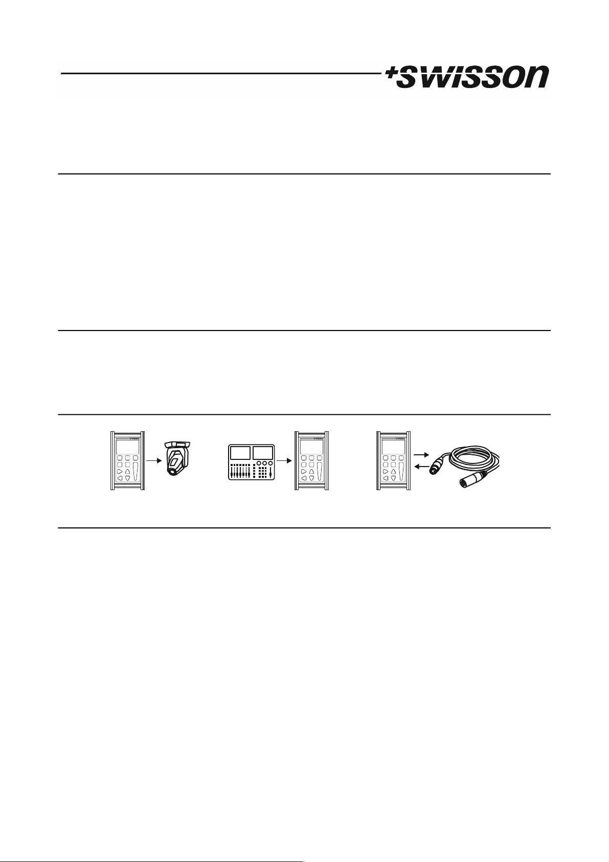
2 Applications.......................................................................................................................................................................4
3 Typical Application............................................................................................................................................................4
4 Unpacking.........................................................................................................................................................................4
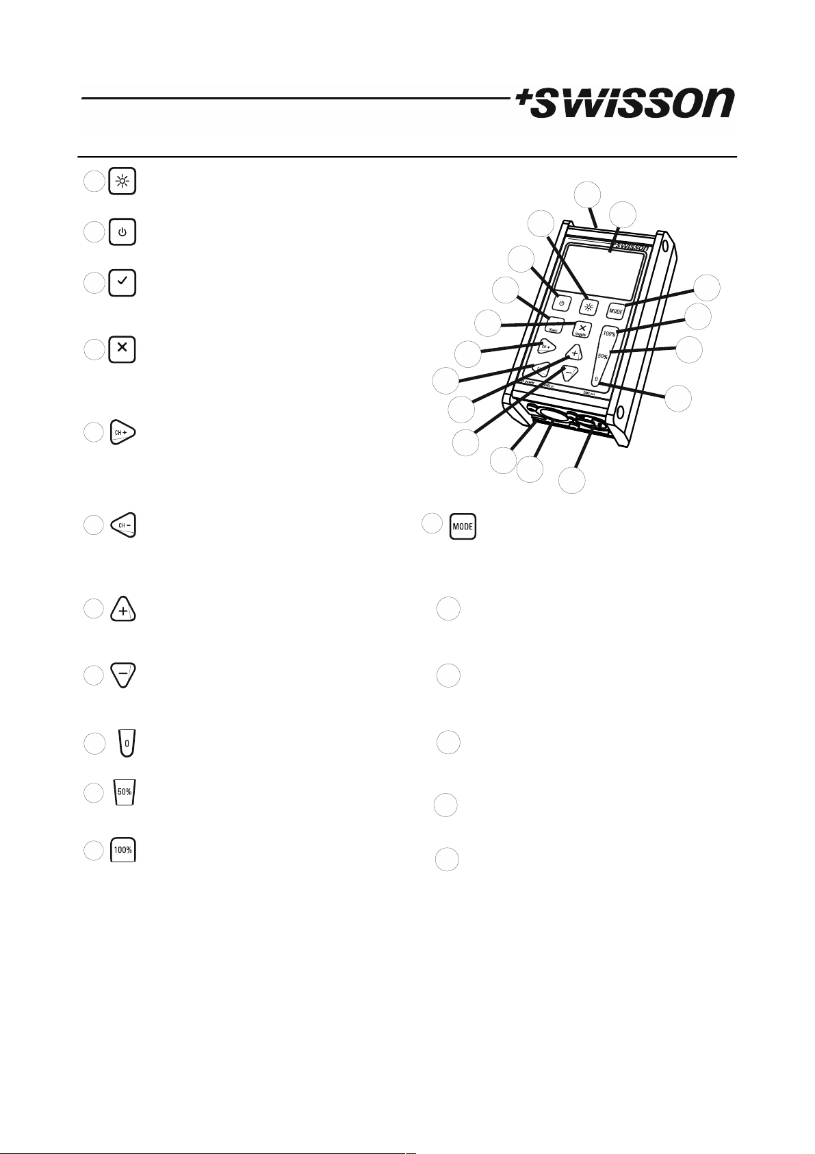
5 Overview..........................................................................................................................................................................5
6 Battery...............................................................................................................................................................................6
7 USB Port............................................................................................................................................................................6
8 Backlight............................................................................................................................................................................6
9 Choose Operating Mo es.................................................................................................................................................6
10 RECEIVE DMX..................................................................................................................................................................7
11 Receiver Options.............................................................................................................................................................8
11.1 STORE SCENE..........................................................................................................................................................8
11.2 SHOW LEVEL AS .....................................................................................................................................................8
11.3 DISPLAY MODE.......................................................................................................................................................8
11.4 ADDRESSES.............................................................................................................................................................9
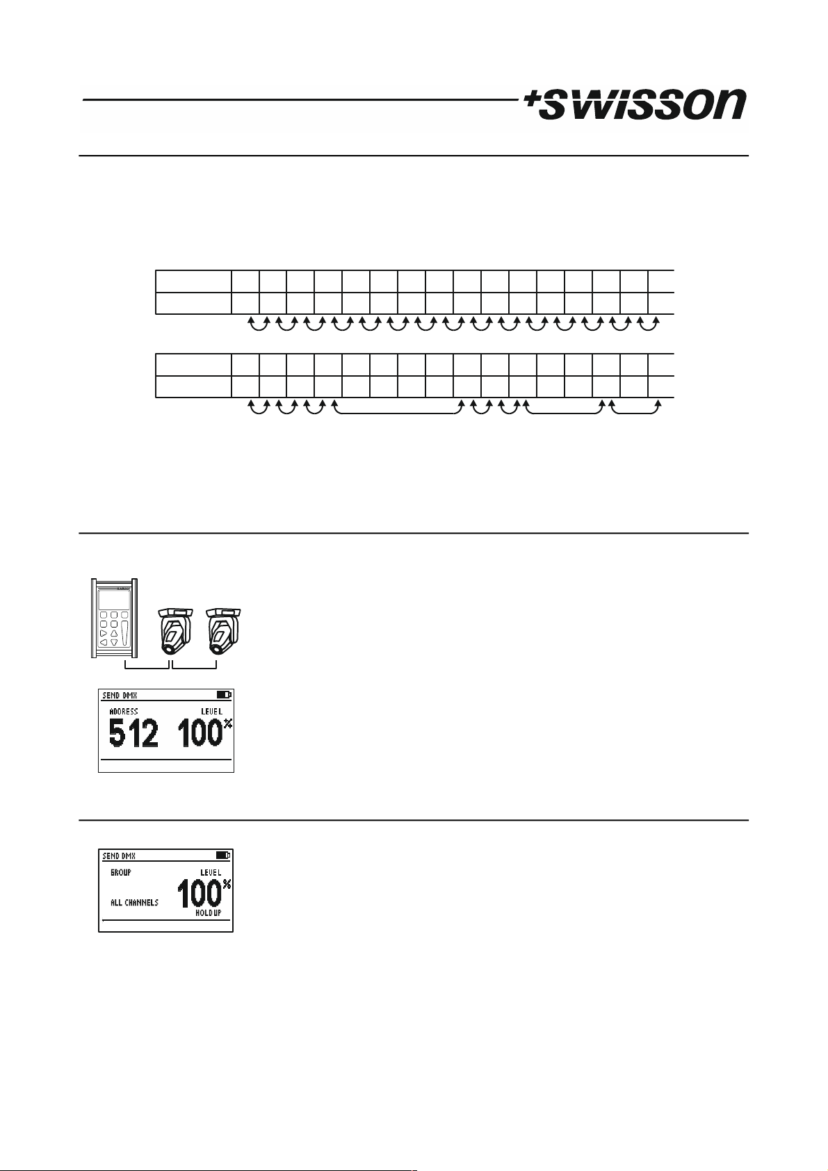
12 SEND DMX.......................................................................................................................................................................9
12.1 Set Level of all Channels.........................................................................................................................................9
12.2 Set Level of Group of Channels (LED)...................................................................................................................10
13 Sen Options.................................................................................................................................................................10
13.1 CLEAR ALL CHANNELS..........................................................................................................................................10
13.2 STORE SCENE........................................................................................................................................................10
13.3 LOAD SCENE.........................................................................................................................................................12
13.4 SHOW LEVEL AS....................................................................................................................................................12
13.5 EDIT MODE...........................................................................................................................................................12
13.6 REFRESH RATE......................................................................................................................................................13
14 CABLE TESTER...............................................................................................................................................................13
15 CHANEL TRACER............................................................................................................................................................13
16 TIMINGS........................................................................................................................................................................15
17 SEQUENCE.....................................................................................................................................................................15
17.1 EDIT SEQUENCE....................................................................................................................................................16
17.2 PLAY SEQUENCE...................................................................................................................................................16
17.3 DELETE SEQUENCE...............................................................................................................................................16
18 FIXTURES.......................................................................................................................................................................16
18.1 PATCH FIXTURES...................................................................................................................................................16
18.2 EDIT FIXTURES......................................................................................................................................................17
19 Connect to PC...............................................................................................................................................................18
20 OPTIONS........................................................................................................................................................................18
20.1 ENTER NAME........................................................................................................................................................18
20.2 LOAD DEFAULT OPTIONS......................................................................................................................................18
20.3 SHOW BINARY ADDRESS......................................................................................................................................18
20.4 Show Min an Max Values...................................................................................................................................19
20.5 CONTRAST............................................................................................................................................................19
20.6 POWER SETTINGS.................................................................................................................................................19
20.7 FIRMWARE UPDATE..............................................................................................................................................20
21 RDM Controller (XMT-350 Only)...................................................................................................................................20
21.1 RDM Discovery.....................................................................................................................................................20
21.2 RDM Main Screen................................................................................................................................................20
21.3 RDM Device Details..............................................................................................................................................21
21.4 RDM Patch DMX A resses.................................................................................................................................21
21.5 RDM Options........................................................................................................................................................22
22 A itional Technical Information..................................................................................................................................23
22.1 Block Diagram XMT Interfaces.............................................................................................................................23
3 PRELIMINARY

22.2 Groun Topologies...............................................................................................................................................23
23 Safety Information........................................................................................................................................................24
24 Technical Data...............................................................................................................................................................24
1 Introduction
The XMT-120A an XMT-350 are the new generation of powerful DMX-512 measurement an test equipment for
architecture, entertainment, film an TV lighting an installations using DMX512. The versatile functions of the XMT-
120A simplify the ebugging of lighting an installations, or any application where DMX is use to control lighting.
The unit can monitor DMX-512 signals as well as analyze an isplay them. The evice can also generate DMX-512
signal an supports the control of more complex DMX-512 fixtures such as moving lights. The testing of RGB LED
lighting with many channels is easy to o with the XMT-120A or with the XMT-350. With a itional features such as
cable tester, timing analysis, sequence e itor, channel "tracer", ip-switch isplay an Min / Max isplay this evice is
i eal for troubleshooting an resolving DMX-512 signal challenges an yet remains very simple to operate.
The XMT can be connecte via USB to a PC. The Win ows software allows managing the fixture library for intelligent
evices an up ating the evice's firmware.
2 Applications
•Concert Lighting
•Live Events
•Multime ia Shows
•Theater
•TV Sets
•Theme Parks
•Architectural Lighting
•Installation
3 Typical Application
4 Unpacking
XMT-120A: The following items are inclu e :
•The evice
•This user manual
XMT-350: The following items are inclu e :
•The evice
•This user manual
XMT-120A-SET: The following items are inclu e :
•The evice
•Nylon case
•1 a apter XLR 3-pin to XLR 5-pin
•1 a apter XLR 5-pin to XLR 3-pin
•This user manual
XMT-350-SET: The following items are inclu e :
•The evice
•Nylon case
•1 a apter XLR 3-pin to XLR 5-pin
•1 a apter XLR 5-pin to XLR 3-pin
•This user manual
4 PRELIMINARY

5 Overview
BACKLIG T
With this button the backlight can be
switche on or off
POWER
With this button the evice can be
switche on or off
OK [OK]
Choose a menu point with this button
Enter special settings
Enter the special settings menu
Cancel [CANCEL]
Escape from a menu point with this
button
Toggle
Toggle values in sen mo e
C ANNEL + [RIG T]
Increase the DMX channel (a ress)
NAVITGATE
Use to navigate to the right in the user
menu
C ANNEL - [LEFT]
Decrease the DMX channel (a ress)
NAVITGATE
Use to navigate to the left in the user
menu
MODE
The operating mo e can be selecte by
pressing the mo e button
VALUE + [UP]
Increase DMX value
NAVITGATE
Use to navigate up in the user menu
DISPLAY
LCD isplay with LED backlight
VALUE - [DOWN]
Decrease DMX value
NAVITGATE
Use to navigate own in the user menu
MICRO-USB SOCKET
Micro-USB socket for power-supply, PC
connection an firmware-up ate
C ANNEL to 0%
Set the DMX value to 0%
(Fast Access Button)
DMX IN
Connector to receive DMX
C ANNEL to 50%
Set the DMX value to 50%
(Fast Access Button)
DMX OUT
Connector to sen DMX
C ANNEL at 100%
Set the DMX value at 100%
(Fast Access Button)
BATTERY
Battery compartment for 9V block battery
5 PRELIMINARY
7
8
9
16
10
17
11
15
6
14
13
12
1
2
(func)
3
(toggle)
4
5
2
5
6
7
8
11
10
12
9
13
14 1 5 16
3
4
1
17

6 Battery
The XMT uses a 9 volt alkaline battery.
Lift to open the battery
compartment.
Pull to remove the battery
compartment.
Check battery pole
positions.
Push the battery on the
spring own into the
compartment.
Push the battery
compartment to the
touch.
If power is supplie to the XMT via the USB port, the battery is isconnecte . As soon as the USB power supply is
remove , the XMT will automatically switch to battery operation. It’s also possible to use a rechargeable 9 volt battery.
The battery is not charged by the XMT.
The battery status of the XMT is isplaye graphically in the upper right corner of the isplay. When USB power is
available, the battery symbol isappears an is replace with a power connection symbol.
In or er to increase the battery life time, the XMT will by efault automatically turn off after not being use for a few
minutes. Please refer to the Power Settings chapter on how to change this behavior.
7 USB Port
The USB port is use to power the XMT an to connect it to a PC. Any 5V USB a apter, which is capable to supply
150mA can be use to power the XMT as well. The USB socket type is: Micro-USB B. The USB cable is not supplie with
the XMT.
8 Backlight
Press the [Backlight] button to turn on an off the backlight.
The backlight uses a lot of energy. The battery life-time may be ramatically re uce when the backlight is use
excessively.
9 Choose Operating Modes
When the [MODE] button is presse , while the evice is in one of the basic operation mo es, a menu will appear on
the isplay.
RECEIVE DMX Mo e to receive an isplay DMX values.
SEND DMX Mo e to e it levels an sen DMX.
RDM CONTROLLER Mo e to operate RDM (available only on the XMT-350).
CABLE TESTER Cable test mo e.
C ANNEL TRACER Mo e to receive a DMX channel an trace the level frame by frame.
TIMINGS Mo e to analyze DMX timings.
SEQUENCE Sequence e itor an player .
6 PRELIMINARY
1
2
3
4
5
USB powere Battery powere
USB A apter

FIXTURE Configure fixtures an patch them.
OPTIONS Options of the XMT.
CONNECT TO PC Mo e to connect the XMT to the PC software.
On the XMT-120A:
Select the esire mo e by using the navigation buttons [CH+] an [CH-].
Press [OK] to confirm the selection or [CANCEL] to return to the previous mo e.
On the XMT-350:
Select the esire mo e by using the navigation buttons [CH+], [CH-], [+] an [-].
Press [OK] to confirm the selection.
10 RECEIVE DMX
Press the [MODE] button an choose RECEIVE DMX. Now, press the [OK] button to enter the receive mo e.
Connect a DMX source to the XMT's DMX in port.
If a DMX signal is receive without any errors, the ata of the DMX signal will be
isplaye .
Choose the DMX a ress with [CH+] an [CH-] buttons. The correspon ing level will be
shown in real time.
If the DMX signal is goo enough to be eco e , but some errors are etecte , the
receive ata will be isplaye while an error sign will appear.
If the incoming DMX signal can’t be eco e by the XMT, BAD SIGNAL will be shown
instea of the value.
If no signal is etecte , NO SIGNAL will be shown instea of the value.
If a DMX signal is receive , but the selecte channel is not available, “--” will be shown
instea of the value.
Note: DMX-512 can transmit up to 512 channels but it’s possible that a controller sen s
less than 512 channels.
7 PRELIMINARY

In receive mo e, the receive signal will be amplifie an sent to the DMX out port. This allows you to connect the
XMT in the mi le of the DMX line an the signal will be terminate at the DMX in port of the XMT.
11 Receiver Options
When the XMT is in receive mo e, press the [OK] button to enter the special settings menu.
STORE SCENE Create a snapshot of the incoming DMX ata an store the values to a scene.
S OW LEVEL AS Choose whether the level is isplaye in percents, ecimal or hexa ecimal.
DISPLAY MODE Select one of the following view types: Normal view, Table view or Graphical view.
ADDRESSES Navigate through all channels or only through channels receiving a non-zero DMX value.
11.1 STORE SCENE
In receive DMX mo e:
•Press [OK] to access receiver options.
•Press [OK] again to access the list of scenes.
•Choose a scene with [UP] an [DOWN] buttons.
•Press [OK] to confirm.
•Press [CANCEL] twice to exit the receiver options.
There are 32 scenes which are accessible from the receive DMX mo e, as well as from the sen DMX mo e. Storing
the receive signal to a scene overwrites all 512 channels of that scene with the currently receive values. The scenes
can be combine to a sequence by using the sequence e itor. See chapter SEQUENCE.
11.2 S OW LEVEL AS
In receive DMX mo e:
•Press [OK] to access the receiver options.
•Choose the SHOW LEVEL AS item with [UP] or [DOWN] buttons.
•Press [OK] to change the level isplay format.
•Press [Cancel] to exit the receiver options.
The levels can be isplaye in percent, ecimal or hexa ecimal.
In the Table view, the levels are always isplaye in percents an 100% is shown as “FL”.
11.3 DISPLAY MODE
In receive DMX mo e:
•Press [OK] to access the receiver options.
•Choose the DISPLAY MODE item using the [UP] an [DOWN] buttons.
•Press [OK] to change the isplay mo e.
•Press [Cancel] to exit the receiver options.
8 PRELIMINARY
Display Mo e:
Normal
Display Mo e:
Table
Display Mo e:
Graph

11.4 ADDRESSES
In receive DMX mo e:
•Press [OK] to access the receiver options.
•Choose the ADDRESSES item with the [UP] an the [DOWN] buttons.
•Press [OK] to change the a ress access mo e.
•Press [Cancel] to exit the receiver options.
When ADDRESSES is set to ALL you can iterate through all channels using the [CH+] an the [CH-] buttons. When
ADDRESSES is set to OPEN, pressing the [CH+] button will cause the XMT to jump to the next higher a ress receiving a
non-zero DMX value. Similarly, pressing the [CH-] button will cause the XMT to jump straight to the next lower a ress
receiving a non-zero value.
Note: This option only applies to the Normal isplay mo e.
12 SEND DMX
Press the [MODE] button an choose SEND DMX. Now, press the [OK] button to enter the sen mo e.
Connect your DMX fixtures to the DMX out port of the XMT.
Use [CH+] an [CH-] buttons to select the a ress.
Use [+] an [-] buttons to set the level for the current channel.
Use [0%], [50%] an [100%] to set level to 0,50% an 100%.
12.1 Set Level of all Channels
Use [CH-] button to select a ress 1.
Use [CH-] button again to access the group of all channels.
Use the [+], [-], [0%], [50%] an the [100%] button to set the level of all channels.
9 PRELIMINARY
25 36 5 58 0 0 0 0 80 78 12 0 0 77LEVEL 0 1
ADDRESS 1 2 3 4 5 6 7 8 9 10 11 12 13 14 15 16
ADDRESSES = ALL
25 36 5 58 0 0 0 0 80 78 12 0 0 77LEVEL 0 1
ADDRESS 1 2 3 4 5 6 7 8 9 10 11 12 13 14 15 16
ADDRESSES = OPEN

12.2 Set Level of Group of Channels (LED)
Use [CH+] an [CH-] buttons to select a group of channels. All groups are locate below
the channel 1.
Use the [+], [-], [0%], [50%] an the [100%] buttons to set the level of a group of
channels.
The available groups are shown below.
13 Send Options
When the XMT is in sen mo e, press the [OK] button to enter the special settings menu.
CLEAR ALL C ANNELS Set all channels to zero.
STORE SCENE Store the e ite values to a scene.
LOAD SCENE Loa a scene.
S OW LEVEL AS Choose whether the level is isplaye in percents, ecimal or hexa ecimal.
EDIT MODE Choose e it mo e. Normal or irect.
REFRES RATE Set the DMX refresh rate for the DMX transmitter.
13.1 CLEAR ALL C ANNELS
In sen DMX Mo e:
•Press [OK] to access the sen options.
•Choose CLEAR ALL CHANNELS with the [UP] an the [DOWN] button.
•Press [OK] to confirm.
•Press [CANCEL] to exit the sen options.
Because the CLEAR ALL CHANNELS item is at the top of the sen options menu, pressing the [OK] button twice will
clear all channels.
13.2 STORE SCENE
In sen DMX mo e:
•Press [OK] to access the sen options.
•Choose STORE SCENE with the [UP] an the [DOWN] button.
•Press [OK] to access the list of scenes.
10 PRELIMINARY
3RD
G B G G G GR R R RB B B B
3RD +1
3RD +2
G
G
B
B
G
G
G
G
G
G
G
G
R
R
R
R
R
R
R
R
B
B
B
B
B
B
B
B
RDG B RDG B R RD DG GB B
RD G B RD G B R RD DG GB B
RD GB RD GB R RD DG GB B
RD G BRD G B
4T
4T +1
4T +2
4T +2
R RD DG GB B
R
R
R

•Choose a scene with [UP] an [DOWN] buttons.
•Press [OK] to confirm.
•Press [CANCEL] twice to exit the sen options.
Note: The scenes in receive DMX mo e an in sen DMX mo e are share . All 512 channels are store into a scene.
Storing to a scene overwrites the scene's previous content. The scenes can be combine to a sequence by using the
sequence e itor. See chapter SEQUENCE.
11 PRELIMINARY

13.3 LOAD SCENE
In sen DMX mo e:
•Press [OK] to access the sen options.
•Choose LOAD SCENE with [UP] an [DOWN] buttons.
•Press [OK] to access the list of scenes.
•Choose the scene with [UP] an [DOWN] buttons.
•Press [OK] to confirm.
•Press [CANCEL] twice to exit the sen options.
All 512 channels of the scene are loa e .
13.4 S OW LEVEL AS
In sen DMX mo e:
•Press [OK] to access the sen options.
•Choose the SHOW LEVEL AS item with the [UP] or with the [DOWN] button.
•Press [OK] to change the level isplay format.
•Press [Cancel] to exit the sen options.
The levels can be isplaye in percents, in ecimal or in hexa ecimal.
13.5 EDIT MODE
In sen DMX mo e:
•Press [OK] to access the sen options.
•Choose the EDIT MODE item with the [UP] / [DOWN] buttons.
•Press [OK] to change the e it mo e. The e it mo e can be NORMAL or DIRECT.
•Press [Cancel] to exit the sen options.
Note: The e it mo e setting oes not affect groups of channels.
Normal Mode
In normal mo e, the level of the current channel may be e ite using the keypa . The a juste level stays store at
when the current channel is change using the [CH+] an the [CH-] keys.
Direct Mode
When changing the a ress in irect mo e, the level of the previous a ress is cleare an the currently set level is
assigne to the new a ress automatically.
To keep the level of an a ress when changing the current channel, it's possible to store its level using the [CANCEL]
key. When the level of the current channel has been store to a value that will stay when changing to another channel,
“STORED” will be shown on the isplay.
12 PRELIMINARY

13.6 REFRES RATE
In sen DMX mo e:
•Press [OK] to access the sen options.
•Choose the REFRESH RATE item with the [UP]/[DOWN] buttons.
•Press [OK] to change the refresh rate.
•Press [Cancel] to exit the sen options.
Available refresh rates are: 5, 10, 15, 20, 25, 30, 35, 40, 44 Hz (frames/sec).
14 CABLE TESTER
Press the [MODE] button an choose CABLE TESTER. Now, press the [OK] button to enter the cable tester mo e.
Connect the cable to test to the DMX in an to the DMX out port. The XMT scans all pin
connections automatically.
If the connection between a
pair of pins is OK, it's
in icate by a straight line
connecting the pins.
Pin 2 is connecte to pin 3.
This is usually an error
with DMX cables.
Pin 2 is shorte with pin 3.
This is usually an error
with DMX cables.
Pin 2 is not connecte .
(broken circuit).
This is usually an error
with DMX cables.
The spee of the scanning can be mo ifie with the [0%], [50%], [100%] buttons.
15 C ANEL TRACER
Press the [MODE] button an choose CHANNEL TRACER. Now, press the [OK] button to enter the channel tracer mo e.
13 PRELIMINARY
NORMAL MODE DIRECT MODE
S
S
S
(toggle)

Connect a DMX source to the XMT's DMX in port.
The level of one channel is trace . The a ress of the current channel is isplaye on the
bottom left of the screen.
Use [CH+] an [CH-] buttons to change that a ress.
Use the [Cancel] button to stop an resume the tracing.
When stoppe a small cursor appears. The position of the cursor is isplaye on the
bottom right of the screen. The first value shows the DMX level an the secon value
shows the time at which this channel was receive relative to the time at which the
tracing was stoppe .
Use [CH+] an [CH-] buttons to move the cursor.
Use [0], [50%] an [100%] buttons to zoom in an out.
Scroll up an own with [+] an [-] when zoome in.
14 PRELIMINARY

16 TIMINGS
Press the [MODE] button an choose TIMINGS. Now, press the [OK] button to enter the timings mo e.
Connect a DMX source to the XMT's DMX in port.
The XMT shows basic DMX-512 timings.
DMX SIGNAL
REFRESH RATE
BREAK LENGHT
MARK AFTER BREAK
CHANNELS RECEIVED
Shows if a DMX signal is OK or faulty.
Shows the numbers of frames receive per secon .
Shows the length of the break in microsecon s.
Shows the mark after break time in microsecon s.
Shows the number of channels receive .
Refresh Rates (indicative only)
<1 frames per secon not compliant to stan ar
1-10 frames per secon very slow, compliant to stan ar but may cause problems with some equipment.
10-25 frames per secon slow
25-44 frames per secon typical for most equipment
44 frames per secon maximum spee when sen ing all 512 channel.
>44 frames per secon only possible when sen ing less than 512 channel. Compliant to stan ar but may cause
problems with some equipment.
Refer to ANSI E1.11 for more etaile information on DMX-512 timings. The accuracy of the XMT's timing
measurement is approximately 1.5 microsecon s.
17 SEQUENCE
Press the [MODE] button an choose SEQUENCE. Now, press the [OK] button to enter the sequence menu.
The sequence menu has three items.
EDIT SEQUENCE Create an e it the sequence.
PLAY SEQUENCE Play an stop the sequence, e it spee an fa e time.
DELETE SEQUENCE Delete the sequence.
15 PRELIMINARY
BREAK
MARK AFTER BREAK
STARTCODE
CHANNEL 1
CHANNEL 2
CHANNEL 3
CHANNEL 4
CHANNEL 512
CHANNEL 511
BREAK LENGTH
USITT DMX-512/1986
≥
88us
MAB LENGTH
≥ 4
us
USITT DMX-512/1990
≥
88us
≥ 8
us
ANSI E1.11-2004
≥
92us
≥
12us

17.1 EDIT SEQUENCE
•Choose the EDIT SEQUENCE item with [UP]/[DOWN] buttons.
•Press [OK] to enter the sequence e itor.
The sequence can be create with up to 100 steps using 32 scenes. The scenes can be recor e in receive an sen
mo e.
Choose a step with the [CH+] an [CH-] buttons.
For each step, choose a scene with the [+] an [-] button.
Set the en of the sequence by choosing scene 0 (will be isplaye as “en ”).
17.2 PLAY SEQUENCE
•Choose the PLAY SEQUENCE item with [UP]/[DOWN] buttons.
•Press [OK] to enter the replay mo e.
•Use the [OK] button to play an stop the sequence.
•Use the [+] button to increase an the [-] button ecrease the replay spee .
•Use [0] an [100%] to increase/ ecrease the fa e time.
17.3 DELETE SEQUENCE
•Choose the DELETE SEQUENCE item with [UP] / [DOWN] buttons an press [OK].
•Press [OK] again to confirm.
18 FIXTURES
Press the [MODE] button an choose FIXTURES. Now, press the [OK] button to enter the fixtures menu.
The fixtures menu has three items.
PATC FIXTURES Patch fixtures to DMX a resses.
CLEAR PATC Clear the entire patch.
EDIT FIXTURES E it fixture efinitions.
18.1 PATC FIXTURES
•Choose the PATCH FIXTURES item using the [UP] / [DOWN] buttons.
•Press [OK] to enter the fixture patch e itor.
A list containing the efine fixtures types appears.
•Select a fixture type with the [+] an [-] buttons, an press [OK].
16 PRELIMINARY
Step 1
Step 2
Step 3
Step 4
Step 5
Step 6
Step 7
Step 8
Scene 1
Scene 2
Scene 15
Scene 16
Scene 16
Scene 8
Scene 9
END
Step 1 Step 2 Step 3 Step 4 Step 5 Step 6 Step 7
Spee Fa e Time

ID The fixture ID. It will be incremente automatically.
FIXTURE Name of the fixture type.
ADDRESS The patch a ress for the fixture.
The XMT proposes the next free DMX a ress as the patch a ress. This
a ress can be change with the [CH+] an [CH-] buttons.
•Press [OK] to patch the evice.
If a fixture is patche , the receive DMX mo e an the sen DMX mo e will show
information about the current channel on the bottom of the screen.
18.2 EDIT FIXTURES
The fixture types can be create an mo ifie on the XMT itself or more conveniently with the XMT Fixture Library
E itor on a computer.
•Choose the EDIT FIXTURES item with [UP] or [DOWN] button.
•Press [OK] to enter the fixture type e itor.
The entire patch will be cleare .
•Press [OK] to confirm.
•Use [+] an [-] button to e it a fixture or CREATE NEW FIXTURE to create a new one.
NAME Name of the fixture.
NUMBER OF CH Number of DMX channels use by this fixture.
CHANNEL DEF Definition of the channel escription.
DELETE FIXTURE Delete the fixture efinition.
Name
•Use [+] an [-] buttons to select NAME.
•Select the cursor position by pressing [CH+] or [CH-] an change the character at the cursor position with [+] an [-].
•Pressing [0] will set the character to a blank space.
•When one press [OK] an the name will be save . Press [CANCEL] keep the ol name.
Number of channels
•Use [+] an [-] buttons to select NUMBER OF CHANNELS.
•Use [+] an [-] to set the number of channels for the fixture
Channel definition
•Use [+] an [-] buttons to select CHANNEL DEF.
A list with all channels of the fixture appears.
•Use [+] an [-] buttons to select the channel.
•Press [OK] to e it the channel escription.
•Select the cursor position by pressing [CH+] or [CH-] an change the character at the cursor position with [+] an [-].
•Pressing [0] will set the character to a blank space.
•When one press [OK] an the name will be save . Press [CANCEL] keep the ol name.
17 PRELIMINARY
Parameter Description
Fixture Name
Fixture ID

19 Connect to PC
The XMT PC Software can be ownloa e from the Swisson website. www.swisson.com
•Install the XMT PC Software before connecting the XMT to the PC.
•Connect the XMT to the PC with a USB cable.
•Press the [MODE] button an choose PC Connection. Press now the [OK] button to enter the PC connection mo e.
20 OPTIONS
Press the [MODE] button an choose OPTIONS. Now, press the [OK] button to enter the options menu.
The options menu has following items.
ENTER NAME Personalize your XMT.
LOAD DEFAULT OPTIONS Loa the factory efaults.
S OW BINARY ADDRESS Show a binary representation of the a ress in the DMX receive mo e an in the DMX
sen mo e.
S OW MIN MAX Show minimum an maximum values in the DMX receive mo e.
CONTRAST Contrast setting for LCD isplay.
POWER SETTINGS Configure power settings of the XMT.
FIRMWARE UPDATE Mo e to perform firmware up ate of the XMT.
20.1 ENTER NAME
Choose the ENTER NAME item with [UP] or [DOWN] button
Press [OK] to enter the name ialog.
Select the cursor position by pressing [CH+] or [CH-] an change the character at the cursor position using [+] an [-].
Pressing [0] will set the character to a blank space.
When one press [OK] an the name will be save . Press [CANCEL] to keep the ol name.
The name is isplaye on the boot screen every time the XMT is turne on.
20.2 LOAD DEFAULT OPTIONS
•Choose the LOAD DEFAULT OPTIONS item with [UP]/[DOWN] buttons.
•Press [OK] to loa the factory efaults.
20.3 S OW BINARY ADDRESS
•Choose the SHOW BINARY ADDRESS item with [UP] or [DOWN] buttons.
•Press [OK] to select between NO, YES 0 an YES 1.
NO Binary a ress isplay is isable .
YES 0 Binary a ress isplay is enable . A ress is isplaye as 0-base binary.
A ress 1 to 512 are mappe to the range of 0 to 511 for binary isplay. This is useful for 9bit ip
switches on DMX fixtures.
YES 1 Binary a ress isplay is enable . The range of the binary a resses is 1 to 512.
18 PRELIMINARY
PC XMT-120A / XMT-350

If enable , the binary representation of the a ress is isplaye below the a ress in
receive DMX mo e an in sen DMX mo e.
20.4 Show Min and Max Values
•Choose the SHOW MIN-MAX item with [UP] or [DOWN] buttons.
•Press [OK] to toggle between YES an NO.
If enable , the min an max values of a level are isplaye below the level in receive
DMX mo e.
20.5 CONTRAST
•Choose the CONTRAST item with the [UP]/[DOWN] buttons.
•Press [OK] to enter the contrast e itor.
•Use [+] an [-] buttons to mo ify the contrast.
20.6 POWER SETTINGS
•Choose the POWER SETTINGS item using the [UP]/[DOWN] buttons.
•Press [OK] to enter the power settings menu.
The power settings menu has three items:
BACKLIG T BRIG TNESS Set the brightness of the backlight.
BACKLIG T DURATION Set the uration of the backlight.
TURN OFF IF IDLE Automatic turn-off time for the XMT when battery operate .
BACKLIG T BRIG TNESS
•Choose the BACKLIGHT BRIGHTNESS item with [UP] or [DOWN] buttons.
•Press [OK] to change the backlight brightness from 10% to 100% in steps of 10%.
BACKLIG T DURATION
•Choose the BACKLIGHT DURATION item with [UP] or [DOWN] buttons.
•Press [OK] to change the backlight uration from 10sec to 2min.
TURN OFF IF IDLE
•Choose the TURN OFF IF IDLE item with [UP] or [DOWN] buttons.
•Press [OK] to change the time after which the XMT will turn off automatically when battery operate .
Possible values are: NO = stays on, 1min, 2min, 3min, 5min, 10min. The time is reset to zero whenever a button of the
keypa is presse .
The XMT will not turn off automatically when it’s USB powere .
19 PRELIMINARY
Binary Address
Min Level
Max Level
The LED backlight of the LCD screen use a lot of energy. Try to set the
backlight as low as possible an the uration of the backlight as short as
necessary to save battery life.

20.7 FIRMWARE UPDATE
•Choose the FIRMWARE UPDATE item with the [UP]/[DOWN] buttons.
•Press [OK] to enter the firmware up ate mo e.
This feature oes the same as PC CONNECTION. See section PC CONNECTION.
21 RDM Controller (XMT-350 Only)
Press the [MODE] button an choose RDM. Now, press the [OK] button to start the RDM controller.
21.1 RDM Discovery
The XMT performs a full iscovery when starting the RDM controller. During iscovery, the XMT searches for
connecte RDM evices. The iscovery can be aborte using the [CANCEL] button.
21.2 RDM Main Screen
After the full iscovery the main screen of the RDM controller is isplaye . An incremental iscovery is running in
backgroun to etect RDM fixtures connecte once the full iscovery is complete .
The main screen shows a list of the RDM evices iscovere .
The evice escription an the DMX a ress is isplaye for all foun RDM evices:
The currently selecte evice is inverte :
A small rotating animation appears when the connection to an RDM evices is lost:
N/A is isplaye instea of the DMX a ress when the RDM evice oes not have a DMX a ress. Typically, evices
such DMX splitters have no DMX a ress:
Each RDM evice has an i entify mo e. A blinking ot shows, which evice is currently in this mo e. By efault, the
XMT-350 puts the currently highlighte evice into i entify mo e. This behavior can be isable . See section 21.5
RDM Options on page 22.
When an RDM respon er is foun , the UID is shown until more etaile information is available.
On the upper right corner, the number of currently connecte evices an the totally etecte number of evice.
20 PRELIMINARY
Other manuals for XMT-120A
2
This manual suits for next models
1
Table of contents