manuals.online logo
Brands
  1. Home
  2. •
  3. Brands
  4. •
  5. Buckleys
  6. •
  7. Test Equipment
  8. •
  9. Buckleys BathyCorrometer Pro' User manual

Buckleys BathyCorrometer Pro' User manual

Other manuals for BathyCorrometer Pro'

2

Other Buckleys Test Equipment manuals

Buckleys PST-100 User manual

Buckleys

Buckleys PST-100 User manual

Buckleys Wet Roof Pro' User guide

Buckleys

Buckleys Wet Roof Pro' User guide

Buckleys ST-AC Pro User manual

Buckleys

Buckleys ST-AC Pro User manual

Buckleys DRY ROOF PRO2 User manual

Buckleys

Buckleys DRY ROOF PRO2 User manual

Buckleys DCCT PRO2 User manual

Buckleys

Buckleys DCCT PRO2 User manual

Buckleys PHD PRO2 User manual

Buckleys

Buckleys PHD PRO2 User manual

Buckleys PST-100 User manual

Buckleys

Buckleys PST-100 User manual

Buckleys ST-AC Pro User manual

Buckleys

Buckleys ST-AC Pro User manual

Buckleys BathyCorrometer Calibration Kit User manual

Buckleys

Buckleys BathyCorrometer Calibration Kit User manual

Buckleys BathyCorrometer CalChecker Pro User manual

Buckleys

Buckleys BathyCorrometer CalChecker Pro User manual

Popular Test Equipment manuals by other brands

Ambit P.F. Series instruction manual

Ambit

Ambit P.F. Series instruction manual

Megger BMM500 Series user guide

Megger

Megger BMM500 Series user guide

RJG Lynx Sensor Tester operating instructions

RJG

RJG Lynx Sensor Tester operating instructions

Mark-10 TT02 Series user guide

Mark-10

Mark-10 TT02 Series user guide

Martel 3001 Operator's manual

Martel

Martel 3001 Operator's manual

ElproSys DiagProg4 instruction manual

ElproSys

ElproSys DiagProg4 instruction manual

Redtech TRAILERteck T05 user manual

Redtech

Redtech TRAILERteck T05 user manual

Venmar AVS Constructo 1.0 HRV user guide

Venmar

Venmar AVS Constructo 1.0 HRV user guide

Test Instrument Solutions SafetyPAT operating manual

Test Instrument Solutions

Test Instrument Solutions SafetyPAT operating manual

Hanna Instruments HI 38078 instruction manual

Hanna Instruments

Hanna Instruments HI 38078 instruction manual

Kistler 5495C Series instruction manual

Kistler

Kistler 5495C Series instruction manual

Waygate Technologies DM5E Basic quick start guide

Waygate Technologies

Waygate Technologies DM5E Basic quick start guide

StoneL DeviceNet CK464002A manual

StoneL

StoneL DeviceNet CK464002A manual

Seica RAPID 220 Site preparation guide

Seica

Seica RAPID 220 Site preparation guide

Kingfisher KI7400 Series Training manual

Kingfisher

Kingfisher KI7400 Series Training manual

Kurth Electronic CCTS-03 operating manual

Kurth Electronic

Kurth Electronic CCTS-03 operating manual

SMART KANAAD SBT XTREME 3G Series user manual

SMART

SMART KANAAD SBT XTREME 3G Series user manual

Agilent Technologies BERT Serial Getting started

Agilent Technologies

Agilent Technologies BERT Serial Getting started

manuals.online logo
manuals.online logoBrands
  • About & Mission
  • Contact us
  • Privacy Policy
  • Terms and Conditions

Copyright 2025 Manuals.Online. All Rights Reserved.

HOME ReassemblyDescription Preparation Disassembly
BathyCorrometer Pro’ Upgrade Kit
Installation manual
Or press ‘Esc’ on your keyboard to close this manual.
1. Description
4. Reassembly
2. Preparation
3. Disassembly
Click on a title below to go to that section:
5. Repairs & test certificate production
Repairs & test certificate production
V 01/11/18
1. Description
The BathyCorrometer®Pro’ Upgrade Kit brings the specification of
older MkV units up to that of the current model with improved display
clarity, the correct negative potential reading and revised battery
and electronics systems.
BathyCorrometer®
M k V t o P R O ’ U P G R A D E M A N U A L
HOME ReassemblyDescription Preparation Disassembly Repairs & test certificate production
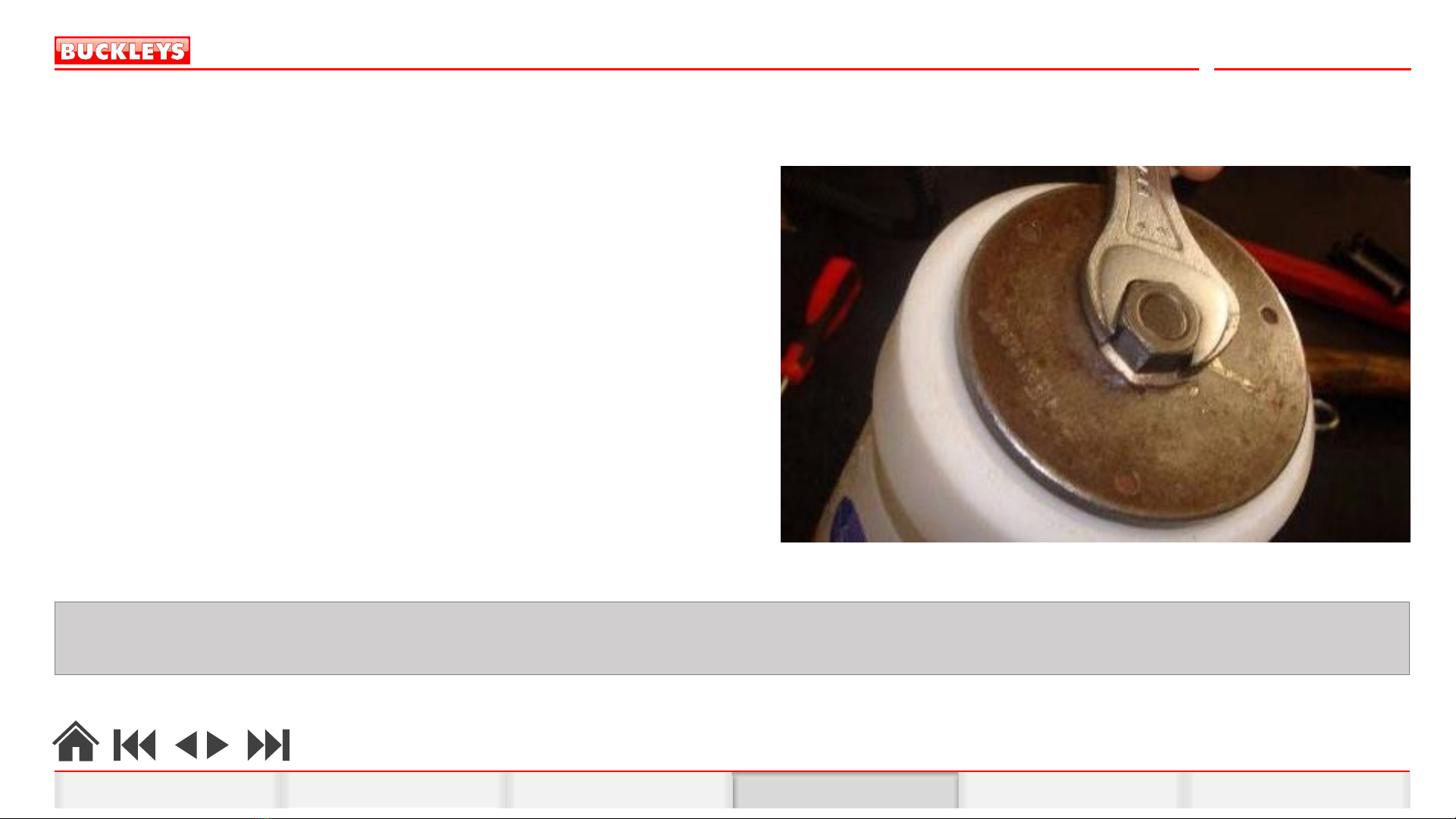
1. 8mm open-ended spanner dealer to source
2. 19mm open-ended spanner dealer to source
3. Thermometer (K-type)/salinity meter 6005-0996
4. 2m/kG calibrated torque wrench 6005-0997
with 19mm socket (½” square drive)
5. Digital volt meter and leads dealer to source
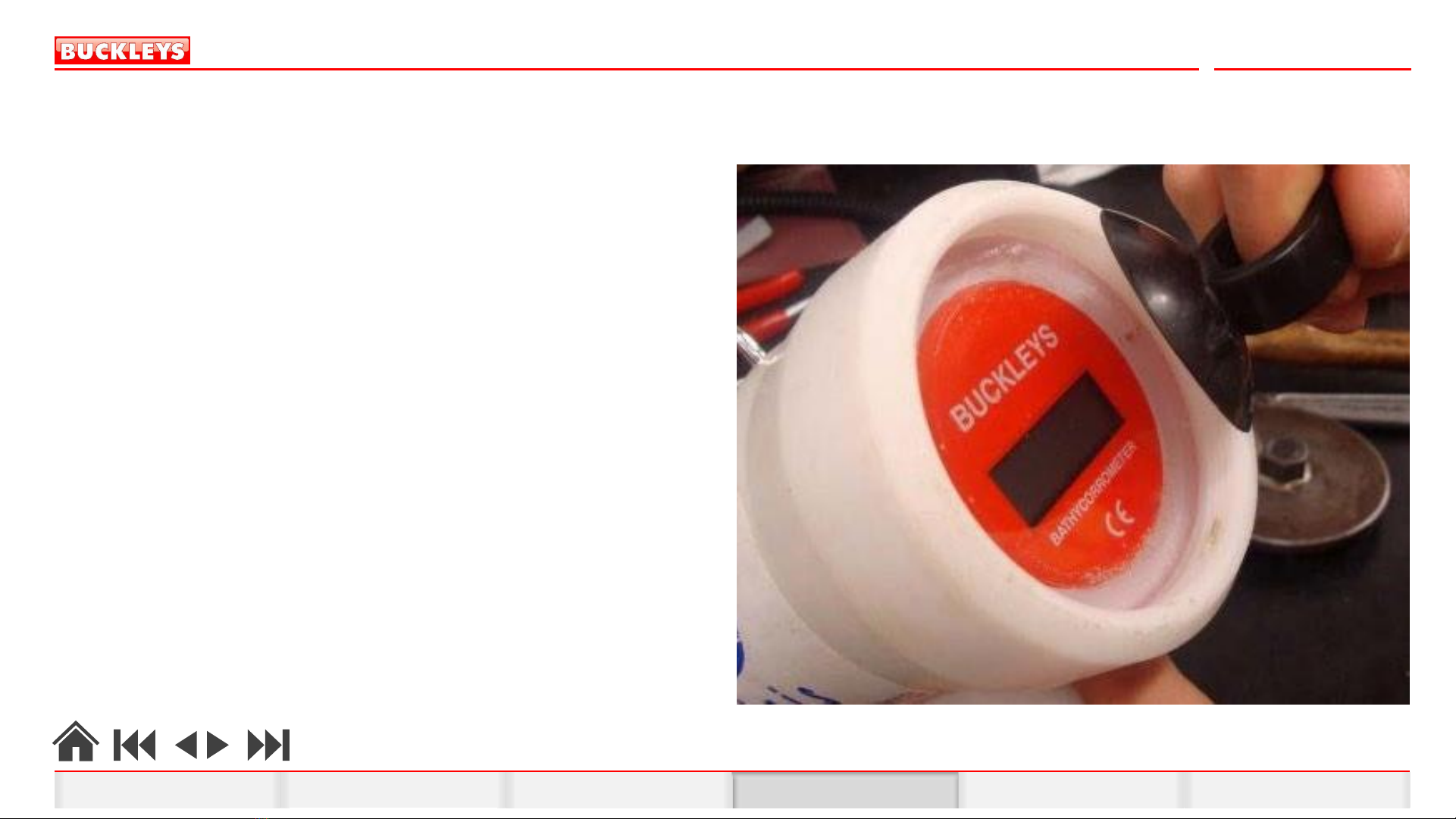
6. BathyCorrometer®service tool (T-bar) 6005-0313
7. BathyCorrometer®locking ring tool 6004-0007
8. Pipe grips dealer to source
9. De-ionized water (10L) dealer to source
10. K-Cell adaptor leads 6004-0018
11. Tamper-evident seal/paint dealer to source
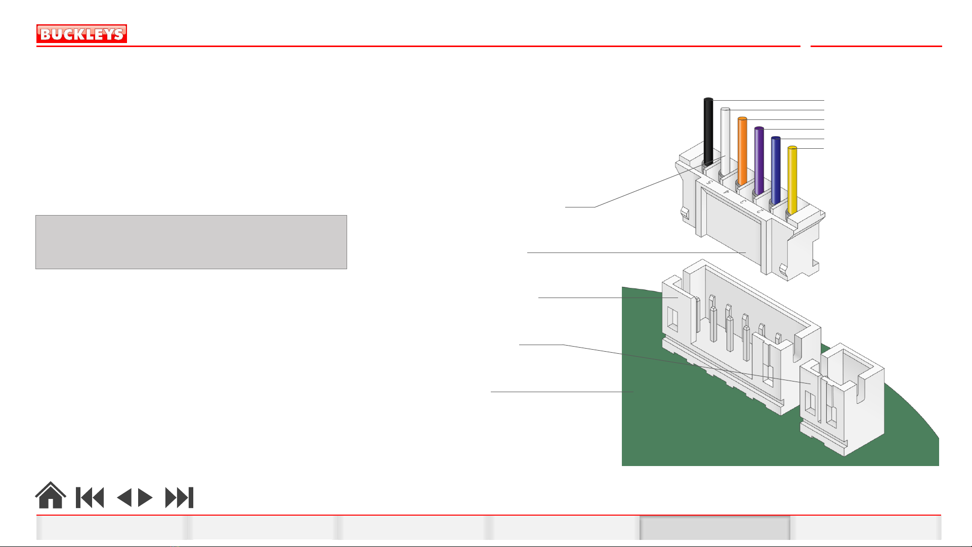
12. Crimp tool JST WC-240 (Farnell 3617270)
13. BathyCorrometer®Calibration Kit 6004-0031
14. Soldering Iron dealer to source
15. Wire cutters dealer to source
16. Long nose pliers dealer to source
17. Lead-free solder dealer to source
18. Cleaning cloth dealer to source
19. Hammer dealer to source
20. Handle sealing plug 6005-0312
21. Half-cell sealing plug 6005-0311
22. Trim Tool 6005-0084
23. Suction puller cup 2006-0036
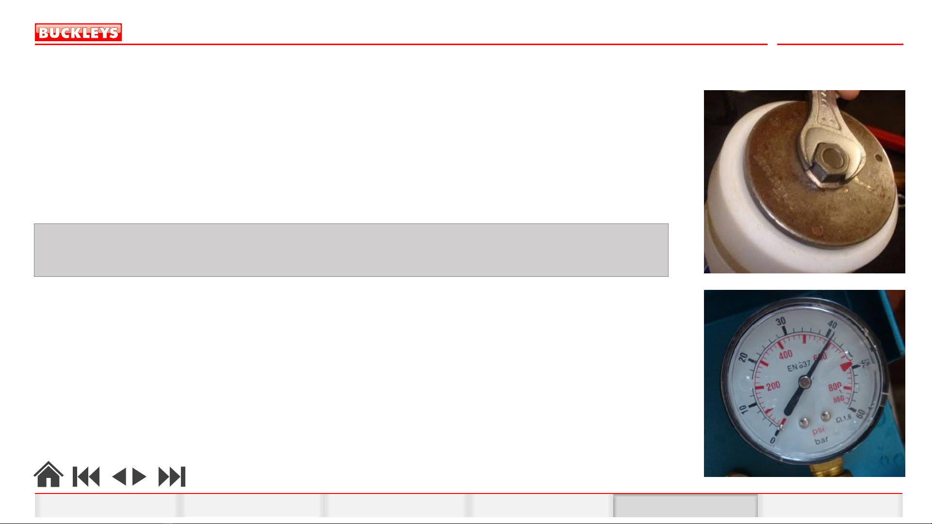
24. Pressure tank capable of 600psi dealer to source
2. Preparation
Workspace
A robust workspace/bench is required and should be clean and free from debris. All testing and calibration equipment such as pressure chambers
and multimeters should be checked and calibrated annually by recognised or approved sources.
Tools required
In order to check and fully test a BathyCorrometer®Pro’, the following service and calibration tools are required:
Items with part numbers may be
purchased from Buckleys
1 2
3 4
5 6
7 8
16
17 14 1512 13911
23 2421 2219 2010 18
BathyCorrometer®
M k V t o P R O ’ U P G R A D E M A N U A L
HOME ReassemblyDescription Preparation Disassembly Repairs & test certificate production
3. Disassembly
Locking Ring Removal
Ensure the area around the locking ring and lens are clean and free from any grit or other debris.
Attention should be given to ensuring the exposed threads are clean as any debris could
damage the threads; making it impossible to achieve a watertight seal during reassembly.
Place the BathyCorrometer®on a firm surface and locate the locking ring removal tool’s three
locating pins in to the holes on the locking ring.
Using a suitable spanner or wrench and socket, unscrew and remove the locking ring by turning
it counter-clockwise. Some assistance to hold the BathyCorrometer®is advised whilst the locking
ring is removed as considerable force may be required.
NOTE: If any of the watertight seals are disturbed, successful pressure testing to 600psi is required before the BathyCorrometer ®Pro’ can be used to take CP readings.
Do not open the BathyCorrometer ®Pro’ unless adequate facilities to pressure test the unit are available.
BathyCorrometer®
M k V t o P R O ’ U P G R A D E M A N U A L
HOME ReassemblyDescription Preparation Disassembly Repairs & test certificate production
3. Disassembly
Lens Removal
Once the locking ring has been removed as described above, the lens can be removed
with the aid of a small suction-puller cup. Place the BathyCorrometer®on a firm surface
and locate the locking ring removal tool’s three locating pins in to the holes on the
locking ring.
Carefully retrieve the lens locating pins (part no. 3009-0010) and remove the large O-ring
(lens seal) from the BathyCorrometer®.
BathyCorrometer®
M k V t o P R O ’ U P G R A D E M A N U A L
HOME ReassemblyDescription Preparation Disassembly Repairs & test certificate production
3. Disassembly
Removing the BCM MkV Electronics
Remove the two retaining screws at the top and bottom of the electronics assembly and withdraw the
electronics assembly from the BathyCorrometer®to gain sufficient access to disconnect the plug connection
on the rear of the assembly. Withdraw the complete electronics unit from the BathyCorrometer®.
Remove the silica gel pouch.
BathyCorrometer®
M k V t o P R O ’ U P G R A D E M A N U A L
HOME ReassemblyDescription Preparation Disassembly Repairs & test certificate production
3. Disassembly
Removing the BCM MkV Electronics
Remove the white multi-plug by cutting the wires as close to the plug as possible.
BathyCorrometer®
M k V t o P R O ’ U P G R A D E M A N U A L
Cut wires as close to multiplug as possible
HOME ReassemblyDescription Preparation Disassembly Repairs & test certificate production
4. Reassembly
BathyCorrometer®
M k V t o P R O ’ U P G R A D E M A N U A L
Preparing the new electronics
Using wire strippers, strip 3mm insulation from each of the 6 wire tails and attach the new, smaller crimp
terminals (part no. 2002-0032) to each wire with a crimp tool.
Carefully insert the 6 terminals/wires into the rear of the new 6-way multi-plug (part no. 1012-0032),
ensuring they lock into place and that the wires are inserted into the multi-plug in the correct order.
See the illustration for the correct multi-plug wiring order.
IMPORTANT: incorrect wiring of the 6-way multiplug is likely to
cause irreparable damage to the BathyCorrometer Pro’s
electronics assembly. Electronics connection plug
Battery connection socket
BathyCorrometer Pro’ wiring harness
Electronics assembly
Electronics connection socket
Black
White
Orange
Purple
Blue
Yellow
Attach the self-adhesive battery isolation disc (part no. 4005-0003)
to the rear of the electronics assembly, taking care not to obscure
the screw attachment holes.
HOME ReassemblyDescription Preparation Disassembly Repairs & test certificate production
4. Reassembly
BathyCorrometer®
M k V t o P R O ’ U P G R A D E M A N U A L
Electronics installation
•Position the wiring harness so that it exits the BathyCorrometer®’s body adjacent to the lower screw fixing point of the
electronics assembly.
•Insert the new silica gel sachet.
•Insert the battery pack sideways, keeping the battery wiring adjacent to the underwater bulkhead wiring harness.
•Connect both the 6-way white multi-plug and the battery’s 2-way multi-plug to the electronics assembly, ensuring the multi-plugs
are positioned correctly.
•Offer the electronics assembly into place taking care not to trap or pinch the wiring.
•Position the electronics assembly so the top and bottom holes align with the fixing points in the body of the BathyCorrometer®.
•Insert and tighten the two self-tapping screws (part no. 2003-0174) until the electronics assembly is secured. Do not overtighten the
screws as this may damage the printed circuit board.
•Before proceeding futher, insert the shorting plug into the base of the handle and ensure the display switches ON and shows a
reading of ‘.000’.
•The BathyCorrometer®Pro’ Retro-Fit Kit is supplied pre-calibrated, so there should be no need to make any adjustments.
•Ensure the protective film is removed from the LCD display.
IMPORTANT: Before installing electronics, take a note of the new electronics’ serial number for certification purposes.
HOME ReassemblyDescription Preparation Disassembly Repairs & test certificate production
4. Reassembly
BathyCorrometer®
M k V t o P R O ’ U P G R A D E M A N U A L
Lens and locking ring replacement
•Ensure all surfaces are as clean as possible before replacing the lens and locking ring.
•Lightly grease a new O-ring (part no. 2011- 0006) and position it into the groove in the BathyCorrometer®’s body.
•Insert the two lens locating pins into the holes within the BathyCorrometer®’s body.
•Position the lens’ holes over the pins and push the lens until it is fully seated against the O-ring.
•Screw in the locking ring, taking care not to cross the threads and tighten fully to 2m/kg (19.6nm) using the locking ring tool and a
calibrated torque wrench with an appropriate socket.
Pressure test
•Pressure test at 600psi for 15 minutes.
•After pressure testing, thoroughly dry the outside of the BathyCorrometer®and look for evidence of water ingress via the lens seal.
•Any evidence of water behind the lens must be rectified and any damaged components replaced before proceeding further.
NOTE: We would strongly advise to undertake a full calibration of the BathyCorrometer at this stage to ensure the half-cell is in
serviceable condition and that all watertight seals are effective.
Refer to the BathyCorrometer Pro’ Service, Diagnostics and Repair Manual for full details.
HOME ReassemblyDescription Preparation Disassembly Repairs & test certificate production