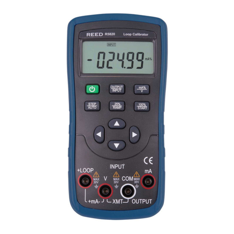
Makerfire N10 User manual

English Instruction for N10 Multifunctional Tester
Model: N10
Dear user:
In order to let you know all the functions of this product faster, get a better user experience, and
avoid misoperation, please read this manual carefully before use and keep it for future reference.

Product Parameters
Model: N10
Input voltage: 3.8V-30V
Input current: 0-3.000A
Capacity measurement range: 0-99999Ah
Energy measurement range: 0-99999Wh
Load impedance measurement range: 1.5
Ω-9999.9Ω
Temperature measurement range:
-20°C~80°C/4°F~176°F
Screen brightness setting: 0-5 a total of 6 levels
Voltage curve range: 3.8V-30V
Product size: 73mm*35mm*10mm
Display screen: 1.44-inch color LCD screen
Product weight: 20.5g (net weight)
Voltage measurement resolution: 0.01V
Current measurement resolution: 0.001A
Voltage measurement accuracy: ±1%
Current measurement accuracy: ±1%
Time measurement range: 0-99 hos 59 mics 59 seds
Temperature measurement error: ±2°C/ ±3.6°F
Delay off screen time: 0-9 minutes
Current curve range: 0.00A-3.00A
Fast charge recognition mode: QC2.0 QC3.0
Refresh rate: 50Hz

Function Interface
1.44-inch color LCD display
USB female interface USB male interface
Multi-function buttons Multi-function buttons
Type-c interface (support PD fast charging)
Type-c interface (support PD fast charging)
Micro USB interface

Instructions
Short press the "Help" button, the interface will display as above:
Long press the "Next" button to switch the data group, the measuring instrument can save and
view 10 groups of data from 1 to 10.
When the data group is group 1-10, the current capacity is stored when the power is turned off,
and the accumulation will continue when the power is turned on next time.
When the data group number is selected, long press the "Help" button to clear the accumulated
capacity value and accumulated energy value in this group of data groups.
Short press the "Next" button to switch to the main interface 2 (fast charging identification
interface)
5
6
7
8
2
1
3
4
1. Voltage measurement value
2. Current measurement value
3. Historical cumulative capacity value
4. Historical cumulative energy value
5. Temperature display
6. Data group number
7. Load Equivalent Impedance
8. Power measurement
Main interface 1 (main measurement interface)

After power on, when the current is greater than the stop current, the system starts to record the
capacity and energy, the time increases, and the REC changes from red to green. Long press the
"Next" button to select the stop current, and short press the button to adjust the value in turn.
The stop current of this product can be set between 0.01-0.30A.
Short press the "Next" button to switch to the main interface 4 (line resistance measurement
interface)
2
1
2
3
4
1
3
1. D+: DP, data positive signal
2. D-: DM, data negative signal
3. Mode display: QC2.0, QC3.0 mode
Short press the "Next" button to switch to the
main 3 (data recording interface)
Main interface 2 (quick charging identification interface)
1. Accumulated capacity after this boot
2. Accumulated energy value after this boot
3. Time display: accumulated record time of the
current load
4. Stop the current setting
REC: Recording status indicator, red REC means stop,
green REC means recording.
Main interface 3 (data recording interface)

2
1
1. The voltage and current value when the tester is directly
connected to the power supply (recommended to connect to a
fixed voltage and current; only support the power input from the
USB-A male terminal, and the output terminal is USB-A female)
2. The voltage and current value when the tester is connected to
the power supply through the chargeing cable to be tested (the
power supply is connected to the same voltage and current as the
previous step)
Main interface 4 (line resistance measurement interface)
R: Charging cable resistance
This interface of this product can be used to measure the line resistance of the charging cable.
The operation steps are as follows:
Step 1: The tester is connected directly to the power supply, adjust the appropriate load
current (recommended to connect to a fixed voltage and current) , long press the "Next"
button to record the data, and the indicator icon on the right stops flashing.
Step 2: Unplug the tester, connect the tester to the power supply through the Micro USB data
cable, adjust the load current to the same current as the first step (recommended to connect to
the same fixed voltage and current as the first step), long press "Next" button to record data,
the right indicator icon stops flashing, the line resistance test is completed, and the line
resistance value of the data cable is displayed.
Note: If the screen of the tester turns black after inserting the data cable in the second step, it
indicates that the voltage difference is too large, and the tester enters the 4.5V power-off state,
the load current needs to be reduced, and the measurement starts from the first step again.
After the line resistance measurement is completed, restart the measurement after the tester is

This interface is the waveform diagram of the measured voltage, which
automatically changes the range within the measurement range of
3.8-30.0V, and displays the voltage fluctuation in real time.
Short press the "Next" button to switch to the main interface 6
(current curve interface)
Main interface 5 (voltage curve interface)
This interface is the current measurement waveform diagram, which
automatically changes the range within the measurement range of
0.00A-3.00A, and displays the current fluctuation in real time.
Short press the "Next" button to switch to the main interface 7 (setting
interface)
Main interface 6 (current curve interface)
powered on next time.
Short press the "Next" button to switch to the main interface 5 (voltage curve interface)

2
3
1
1. Delay off screen time
2. Screen brightness
3. Temperature unit switching
Long press the "Next" button to select the delay screen off time, brightness level, and
temperature unit switching in turn. Long press the "Next" button to enter the screen off time
setting, select the corresponding number and display it in reverse, and short press to cyclically
modify the value, , the values are changed in a sequence of 10 values from 0 to 9, where 0 is
always on.
Long press the "Next" button to enter the screen brightness setting, select the corresponding
number and display it inversely, short press to change the size of the number, the larger the
number, the brighter the screen, there are 6 levels of settings.
Long press the "Next" button to enter the temperature unit switching, the corresponding
number is selected and displayed inversely, and a short press can switch between 0 and 1, 0 is
Celsius, 1 is Fahrenheit.
Long press the "Next" button to exit modifying settings. (The above settings must be entered
into the first interface from this interface to save)
Main interface 7 (setting interface)

Warm tips
This product supports forward and reverse input and output detection, current flow direction
indication, and alarm reminder functions.
Temperature alarm: exceeds 45℃, the temperature display will flash; voltage alarm: less than
3.8V or greater than 30V, the voltage display will flash; current alarm: greater than 3A , the
current display will flash.

Table of contents

