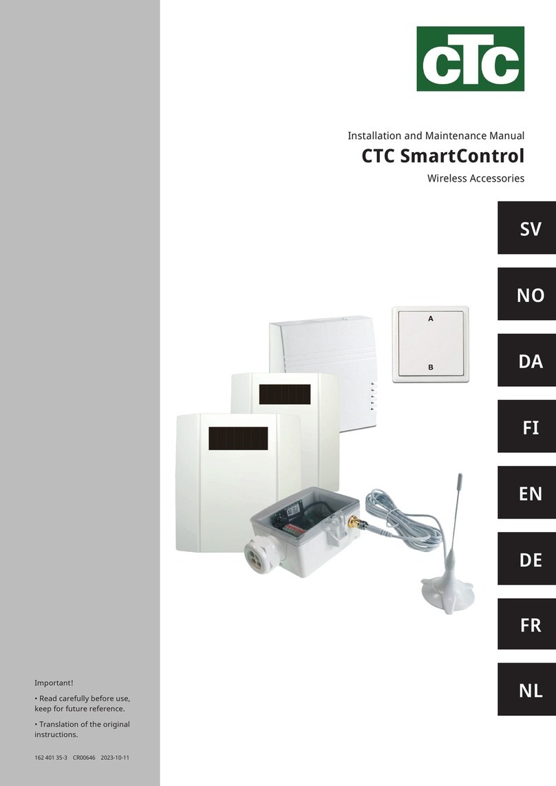
CTC Union Expansion EnergyFlex Manual

Providing sustainable energy solutions worldwide
162 505 78-1 2020-10-13
Important!
• Read carefully before use, keep for future reference.
• Translation of the original instructions.
Installation and Maintenance Manual
CTC Expansion EnergyFlex


162 505 78-1 2020-10-13
Installation and Maintenance Manual
CTC Expansion EnergyFlex

4CTC Expansion Energyflex
4.3.6 Pool ____________________________________ 23
4.3.7 Valve 2 tanks (Y30) ________________________ 23
4.3.8 Valve bedrock (Y31) _______________________ 23
4.4 Sensor installation ____________________________________________24
4.4.1 Sensor connection (extra low-voltage
protection) _______________________________ 25
4.4.2 Factory-fitted sensors _____________________ 26
4.4.3 Resistance level of the temperature sensors___ 27
4.5 Wiring diagram ________________________________________________ 28
4.6 Connection table for Expansion Card A3 ____________29
5. Detailed menu descriptions _______________________________ 30
5.1 Navigate on the touchscreen_____________________________30
5.2 Start menu ______________________________________________________30
Installer ___________________________________________________________________31
5.3 Define_____________________________________________________________31
5.3.1 Def. Diff thermostat function ________________ 31
5.3.2 Def. Pool ________________________________ 32
5.3.3 Def. Solar Panel __________________________ 32
5.3.4 Def. DHW/DHW circulation _________________ 32
5.4 Settings __________________________________________________________33
5.4.1 Settings Diff thermostat function_____________ 33
5.4.2 Settings Solar Panel _______________________ 33
5.4.3 Settings DHW circulation___________________ 37
5.4.4 Settings Pool_____________________________ 38
5.5 Operation data_________________________________________________39
5.5.1 Solar Panel ______________________________ 39
5.5.2 Operation data, Pool ______________________ 41
5.5.3 Operation data DHW circulation _____________ 41
5.6 Service____________________________________________________________42
5.6.1 Function test _____________________________ 42
5.7 Alarm texts and troubleshooting/
appropriate measures_______________________________________ 44
Innehållsförteckning
1. Technical data _______________________________________________________ 6
Delivery includes:________________________________________________________6
Accessories_______________________________________________________________6
2. EnergyFlex _____________________________________________________________ 7
2.1 System options__________________________________________________8
2.1.1 EnergyFlex schematic diagrams ______________ 9
2.1.2 EcoSol - Exemple CTCEcoHeat and
CTCEcoZenithi255 H/L ___________________ 10
3. System structure _________________________________________________ 11
3.1 Solar Panel______________________________________________________ 11
3.1.1 Solar system 1 ___________________________ 11
3.1.2 Solar system 2 ___________________________ 12
3.1.3 Solar system 2b with solar coil ______________ 13
3.1.4 Solar system 3 ___________________________ 14
3.1.5 System option: bedrock heating_____________ 15
3.2 Pool________________________________________________________________16
3.3 Diff thermostat function_____________________________________ 16
3.4 DHW circulation
(DHW circ)_______________________________________________________16
3.5 Parts list _________________________________________________________17
4. Installation____________________________________________________________ 18
4.1 Safety switch___________________________________________________19
4.2 Communication between extension card and
main product___________________________________________________19
4.3 High voltage ____________________________________________________19
4.3.1 Pump, solar panel (G30, PWM)
Wilo Stratos Para _________________________ 19
4.3.2 Circulation pump, solar collector (G30)
GrundfosUPM3Solar _____________________ 20
4.3.3 Pump bore hole charging (G31, on/off) _______ 22
4.3.4 Pump, intermediate heat exchanger solar
panels (G32) PWM ________________________ 22
4.3.5 Pump tank transfer (G46, on/off) ____________ 22
Enertech AB provides the information with reservation for any typing errors and subject to modification.
Information for the property owner to note
Complete the fields below. This information is useful if any servicing work is required
Product : Manufacturing number:
Installation company Tel. no.
Date Name
Electrical installation company Tel. no.
Date Name

5CTC Expansion Energyflex
CTC Expansion EnergyFlex
With CTC Expansion EnergyFlex, you can control your
solar collectors or heat your pool, for example, directly
from the menus of your CTC product, providing an
integrated control system.
Positioning
Place the control unit indoors on a wall next to the
product. The control unit must be positioned so that
normal service procedures can be carried out. There
should be at least 0.5 m of free space in front of the
unit. Ensure that the screws fixing the cover to the unit
are easily accessible.
Safety instructions
Installation must be carried out by a qualified electrician.
This device can be used by children from the age of
three years and above and by people with reduced
physical, sensory or mental ability or lack of experience
or knowledge if they have been taught, either with
supervision or with the instructions provided, how to
use the device safely and understand the risks involved.
Children should not play with the device. Cleaning and
maintenance should not be carried out by children
without supervision.
System requirements
Program version for the display card must be
2014-12-19 or later.
CTC Expansion EnergyFlex complements the following
products with several additional functions (refer to the
"System Design" chapter.
CTCEcoHeat400
CTCEcoZenithi250/i255
CTC GSi
CTC GS
CTCEcoZenith i350/i360
CTCEcoVent i350F/i360F
Congratulations on your new product

6CTC Expansion Energyflex
C
B
Providing sustainable energy solutions worldwide
162201 22 2014-04-28
Installations- och skötselanvisning
CTC Solstyrning/
Expansionskort
DE
A
230V 1N~.
10 A
10 A
4 A
230V 1N~.
0/66k, 10/41.8k, 15/33.5k, 20/27.1k, 25/22k,
30/18k, 35/14.8k, 40/12.2k, 50/8.4k, 60/6.0k,
70/4.3k, 80/3.1k, 90/2.3k, 100/1.7k
-10/960, 0/1000, 10/1039, 20/1077, 30/1116,
40/1155, 50/1194, 60/1232, 70/1271,
80/1309, 90/1347, 100/1385, 120/1461,
140/1535
379 x 279 x 131 mm
EnergyFlex kit 400
Pipe kit, pre-bent pipes, connections
and insulation for “solar output”.
CTC Flowbox Installation kit GSi EHS
Accessories
The most important accessories for
supplementing solar energy and EnergyFlex are
shown below.
Delivery includes:
A 1 x electrical connection box with extension card
B 2 x NTC 22k sensors
C 2 x RJ-45 communication cables
D 1 x Installation and Maintenance Manual
E 1 x flange grommet including cable penetrations
Supply
Max fuse size
Total max. load CTCExpansion EnergyFlex
Max load relay output
Electrical data 3-way valve
Sensor (extra-low voltage protection), NTC22k,
°C/ohm
Solar panel sensor*, type PT1000,
°C/ohm
Measurements (w x h x d)
1. Technical data

7
CTC Expansion EnergyFlex
1
!Connecting external systems can seriously affect the operation and performance
of the indoor module and can therefore produce undesirable effects if the system
is not installed correctly.
If you are unsure how to make the connection, contact CTC for suggestions on
how to install the system.
2. EnergyFlex
EnergyFlex is a collective term that describes CTC’s unique options for
maximum flexibility and simple interconnection between difference heat
sources. The most common combination is a heat pump and electric boiler.
The CTC EcoZenith i250/i255, CTC EcoZenith i350/i360 and EcoVent
i350F/360F indoor modules are equipped for connection with:
• CTC EcoPart Heat Pump (ground source heat pump)
• CTC EcoAir Heat Pump (air/water heat pump)
All EnergyFlex heat pumps/indoor modules have built-in functionality so you
can easily supplement with:
• Solar Energy
• Additional tanks
• Water-jacketed stove
• Wood, electric, pellet and gas boilers
• Pool
EnergyFlex works with heat pumps/indoor modules CTC EcoHeat 400,
CTC EcoZenith i250/i255, CTC GSi, CTC GS, CTC EcoZenith i350/i360
and CTC EcoVent i350F/i360F.
iEnergyFlex Heat Pumps
•CTCEcoHeat 400
•CTC GS
•CTC GSi
iEnergyFlex Indoor Modules
•CTCEcoZenith i250/i255
•CTCEcoZenith i350/i360
•CTCEcoVent i350F/i360F
(CTC EcoZenith i550/i555
comes with a factory-fitted
extension card)
The picture shows the possible connections. The installation engineer fits expansion tank, safety valves, bleeders, etc. and sizes the system.

8CTC Expansion EnergyFlex
Example of wood-fired system with group of chargers. Energyflex can also be used to draw energy, e.g. to heat a
swimming pool.
2.1 System options
The flexibility in the heat pump/indoor module is optimised because the
products provide functionality for up to 5 basic systems:
• Solar system 1
Charging from solar panel only to H-tank (CTC EcoHeat 400/CTC
EcoZenith i255) or EHS-tank.
• Solar system 2
Charging from solar panel to buffer tank CTC EcoTank + CTC
EcoHeat400/CTC EcoZenith i255.
• Solar system 3
Charging from solar panel either to X-volume or to CTC EcoHeat 400/
CTC EcoZenith i255 or EHS-tank.
The solar energy systems also enable recharging of bedrock or collect
energy for an extra tank, with or without a solar coil.
• Diff thermostat function
The diff thermostat function is used to transfer heat from, for example,
a buffer tank or existing wood boiler to an H-tank or EHS-tank. The
diff thermostat function can be connected to an existing PCB in the
heat pump/indoor module, while "Solar systems 1, 2, 3" and the Pool
system require the product to be supplemented with the CTC Solar
Control/Extension Card accessory.
• Pool
The pool is connected to the heating circuit via a 3-way valve. A heat
exchanger should be fitted to separate the liquids.
Important for wood-fired heating
The integrated "Diff thermostat function" control initiates the charge from,
e.g., the existing wood-fired system or fireplace when the temperature is
higher than it is in the main tank.
Bear in mind that it can also be a good idea to install an automatic charger
that can protect the wood-fired system from condensation, etc.
If the wood-fired system needs more water than the 223 litres contained in
the main product (CTCEcoHeat 400 or CTCEcoZenith i255), the system
needs to be supplemented with an accumulator tank.

9
CTC Expansion EnergyFlex
M
HHX
EHS
EcoTank
H
EHS
M
HEHS
EHS
H
HB50
G50 G51
EHS
H
B46
G46
Y11
G99
G98
05
EHS
B47
2.1.1 EnergyFlex schematic diagrams
Solar system 2 Solar system 3Solar system 1
Solar: Heat bedrock option Solar: Alternative solar coil
(only "Solar system 2" with CTCEcoTank)
Diff thermostat system Pool system
The picture shows the possible connections. The installation engineer fits expansion tank, safety valves, bleeders, etc. and sizes the
system.

10 CTC Expansion EnergyFlex
H
2.1.2 EcoSol - Exemple CTCEcoHeat and CTCEcoZenithi255 H/L
CTC EcoHeat and CTC EcoZenith i255 H/L have a water volume of 223 litres with layered disc and solar output.
Solar output (3/4) is a part of EnergyFlex.
CTCEcoheat 400
(223 litres with layered disc and
solar output).
223 litres
223 litres
Solar output
(3/4)
223 litres
CTCEcoZenith i255 H/L
(223 litres with layered disc and solar
output).
Solar output (3/4)
H. Symbol for tank volume in CTC EcoHeat 400
and CTCEcoZenithi255.
The tank in the CTC EcoHeat 400 and CTC EcoZenith
i255 will be designated as H-tank (main tank).
Energy can be collected through the solar outputs (solar
panels, wood-fired boiler) or generated (swimming pool).
Available as accessories are pre-bent pipes with
couplings and insulation to facilitate installation.
The EnergyFlexkit400 pipe kit
accessory fitted to H-tank.
Table of contents
Other CTC Union Control Unit manuals
Popular Control Unit manuals by other brands

Festo
Festo Compact Performance CP-FB6-E Brief description

Elo TouchSystems
Elo TouchSystems DMS-SA19P-EXTME Quick installation guide

JS Automation
JS Automation MPC3034A user manual

JAUDT
JAUDT SW GII 6406 Series Translation of the original operating instructions

Spektrum
Spektrum Air Module System manual

BOC Edwards
BOC Edwards Q Series instruction manual

KHADAS
KHADAS BT Magic quick start

Etherma
Etherma eNEXHO-IL Assembly and operating instructions

PMFoundations
PMFoundations Attenuverter Assembly guide

GEA
GEA VARIVENT Operating instruction

Walther Systemtechnik
Walther Systemtechnik VMS-05 Assembly instructions

Altronix
Altronix LINQ8PD Installation and programming manual
