10 Locations and Functions of Parts
gINPUT area
1PROMPTER 1, 2 (tele-prompter input) connectors
(BNC-type)
Input a teleprompter signal to either of the two connectors. The
input signal is output from the other connector as is (loop-
through output). If loop-through output is not used, terminate
the unused connector at 75 ohms. If the signal used is a 1.0
Vp-p, 75-ohm signal, it may be output from the PROMPTER
OUT connector of the video camera with a frequency
bandwidth of 5 MHz, regardless of signal format.
2REFERENCE connectors (BNC-type)
Input an HD tri-level reference sync signal or SD reference
sync signal (black burst signal) to either of the two connectors.
The input signal is output from the other connector as is (loop-
through output). If loop-through output is not used, terminate
the unused connector at 75 ohms.
The type of reference signal is selected using the setup menu,
or using the MSU-1000 series Master Setup Unit.
For details on the setup menu, contact a Sony service or sales
representative.
Note
To use the VBS signal of the HKCU1001 SD Encoder Unit or
the HKCU1003 Multi Interface Unit (when SC phase lock is
required), use an SD reference sync signal (black burst
signal).
hOUTPUT area
1SYNC (sync signal output) connector (BNC-type)
Used for output of SD composite sync signal or an HD tri-level
sync signal from the internal sync signal generator. (Factory
setting: SD composite sync)
For details on signal selection, contact a Sony service or sales
representative.
2CHARACTER (character output) connector
(BNC-type)
Outputs the self-diagnostic results or the setup menu as an SD
monochrome analog video signal.
3AES/EBU connector (BNC-type)
Outputs an AES/EBU format digital audio signal input to a
video camera.
iCAMERA connector (optical fiber connector)
Used to connect a video camera, using an optical fiber cable.
All video camera signals, including power supply, control,
video, and audio, are sent and received over one optical fiber
cable.
Note
Dust on the connection surface of the optical fiber cable may
result in transmission errors. When not connected, always
cover the end of the connector with the supplied cap.
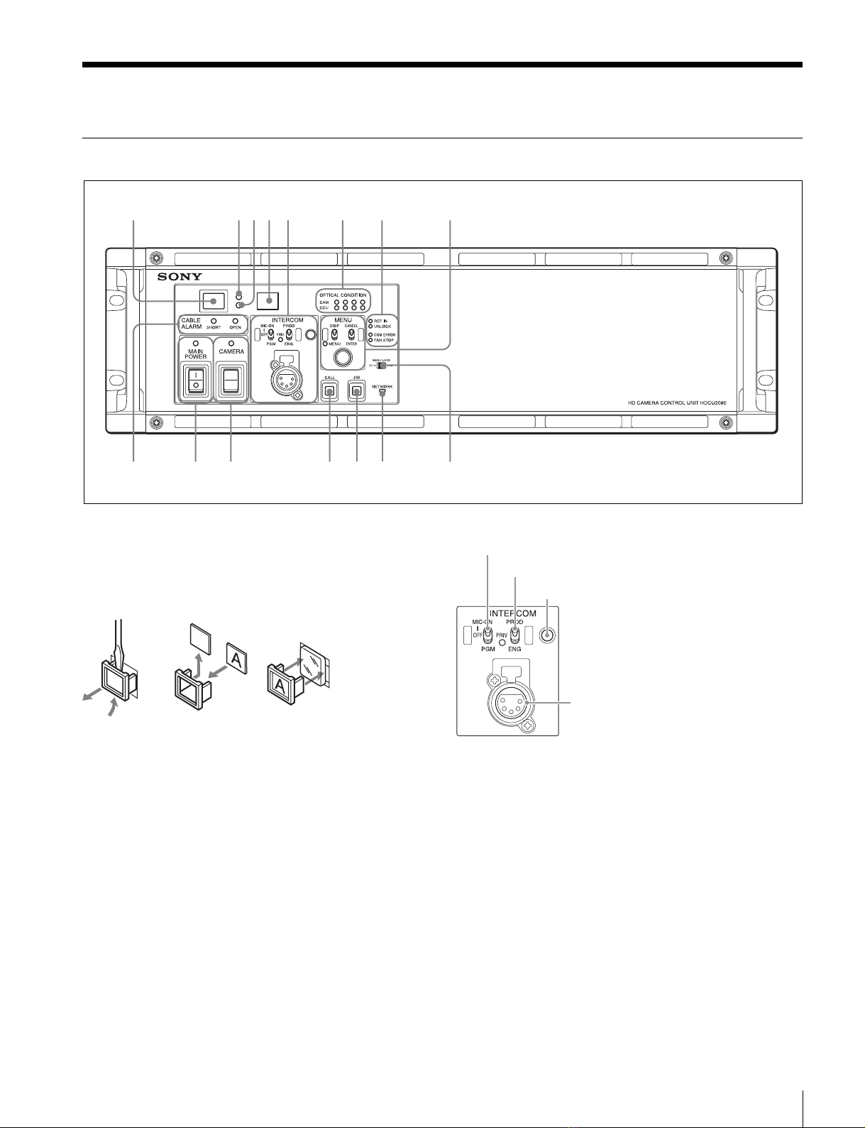
jINTERCOM/TALLY/PGM (intercom/tally/program
audio) connector (D-sub 25-pin)
Used for input and output of intercom, tally, and program audio
signals. Connect to the intercom/tally/program audio
connector of the intercom system.
Flag function: 10-pin is assigned for the output pin of the Flag
function.
kMIC REMOTE (microphone remote) connector (D-sub
15-pin)
Using this connector, the video camera’s microphone input
level may be set by external equipment such as an audio
mixer, in five level (–60, –50, –40, –30, and –20 dB).
When shooting, set the volume to a level appropriate for the
audio conditions.
This connector also outputs red, green and yellow tally
signals.
The microphone input level may also be set using the setup
menu or an RCP. For details on the setup menu, contact a
Sony service or sales representative.
lWF REMOTE (waveform monitor remote) connector
(D-sub 15-pin)
Used to attach to the appropriate connector on a recall-type
waveform monitor when operating the waveform monitor
display using an MSU-1000 series Master Setup Unit or an
RCP-1000 series Remote Control Panel. On the recall-type
waveform monitor, set/preset the display mode to waveform
monitor, and then select (recall) that mode externally.
For details on these operations, refer to the Master Setup Unit
or Remote Control Panel manuals.
mTRUNK LINE connector (D-sub 9-pin, RS-232C
standard)
Used to connect to the CCU connector on a video camera via
an RS-232C interface. Used mainly for communication with
equipment on the camera side.
Communication with up to two channels is available.
nRCP/CNU connector (round 8-pin)
Used to connect to an MSU-1000 series Master Setup Unit,
CNU-700 Camera Command Network Unit, or RCP-1000
series Remote Control Panel via a CCA-5 Connection Cable.
Control signals are sent and received via this connector.
When using an RCP-1000 series unit, power is also supplied.
oI/O PORT connector (D-sub 15-pin)
Used for remote control using an external control device.
Note
Use of a D-sub case wider than 42 mm can cause interference
at connectors 2, 4, 5.
It is recommended that you use a JAE-made DA-C1-J10.
pAUX REMOTE connector (round 8-pin)
This is used to connect a sub-camera RCP for operating a
sub-camera.
qTRUNK A connector (round 12-pin)
Used to connect to the CCU connector on a video camera via
an RS-232C or RS-422A interface.
Communication with up to two channels is available.