CTC Union TCT301 Series User manual

TCT301 Series Termination BoxTCT301 Series Termination Box
1 Triaxial Sensor Input1 Triaxial Sensor Input
Product ManualProduct Manual

2
• Introduction...................................................................3
• Product Description...........................................................3
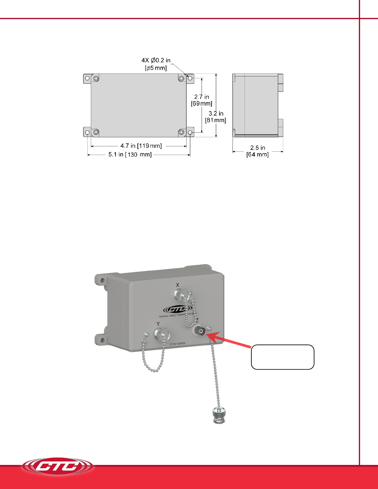
• Product Dimensions...........................................................4
• Mounting Instructions .........................................................5
• Conduit Entry .................................................................6
• Grounding ....................................................................7
• Sensor Installation ............................................................9
• Post Installation Testing ..................................................... 12
• Maintenance ................................................................ 13
• Warranty and Refund Information............................................ 14
T C

3
I
CTC termination box solutions allow for the monitoring of remotely-mounted
vibration sensors, which would otherwise be restricted to human access due to
safety considerations.
TCT301 Series Termination Box Overview: One triaxial sensor input (three
measurement channels), polycarbonate enclosure
The TCT301 Termination Boxes are a common cable termination point for
bringing compatible cables for triaxial sensors into a termination box for routine
data collection with portable data collectors. A cover featuring four self-tapping
screws allows the box to be sealed from the elements.
4
P D
Data Collector
Access (BNC)
Figure 1. Dimensions
Figure 2. Diagram
Side View Rear View

5
M I
Molded mounting brackets are included on the enclosure. Wall anchoring screws
are not included.
Mounting
Holes
0.22 in./5.59 mm
Figure 3. Cable Termination Box Rear View
6
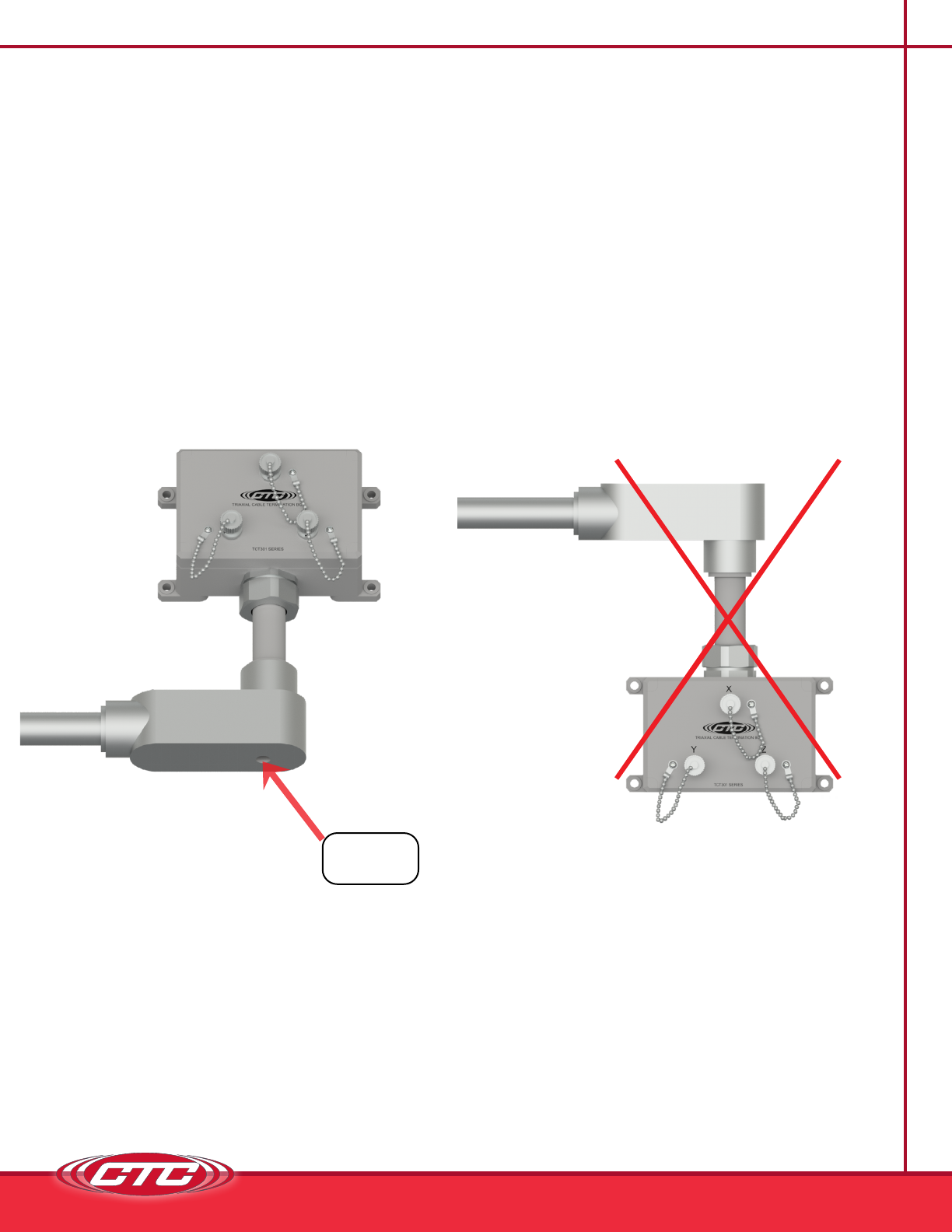
C E
If you have purchased an enclosure without cable entries provided, you should add
your own entry prior to mounting the termination box. CTC does not recommend
putting holes in the top of the enclosure as it will cause restricted access to the
wire termination connection points and also allow possible moisture ingress.
Note: To prevent a buildup of condensation inside the enclosure, provide drainage
by drilling a hole in the lowest point of the conduit.
Correct
Figure 4. Conduit Entry for Termination Box
Incorrect
Drill Drain
Hole Here

7
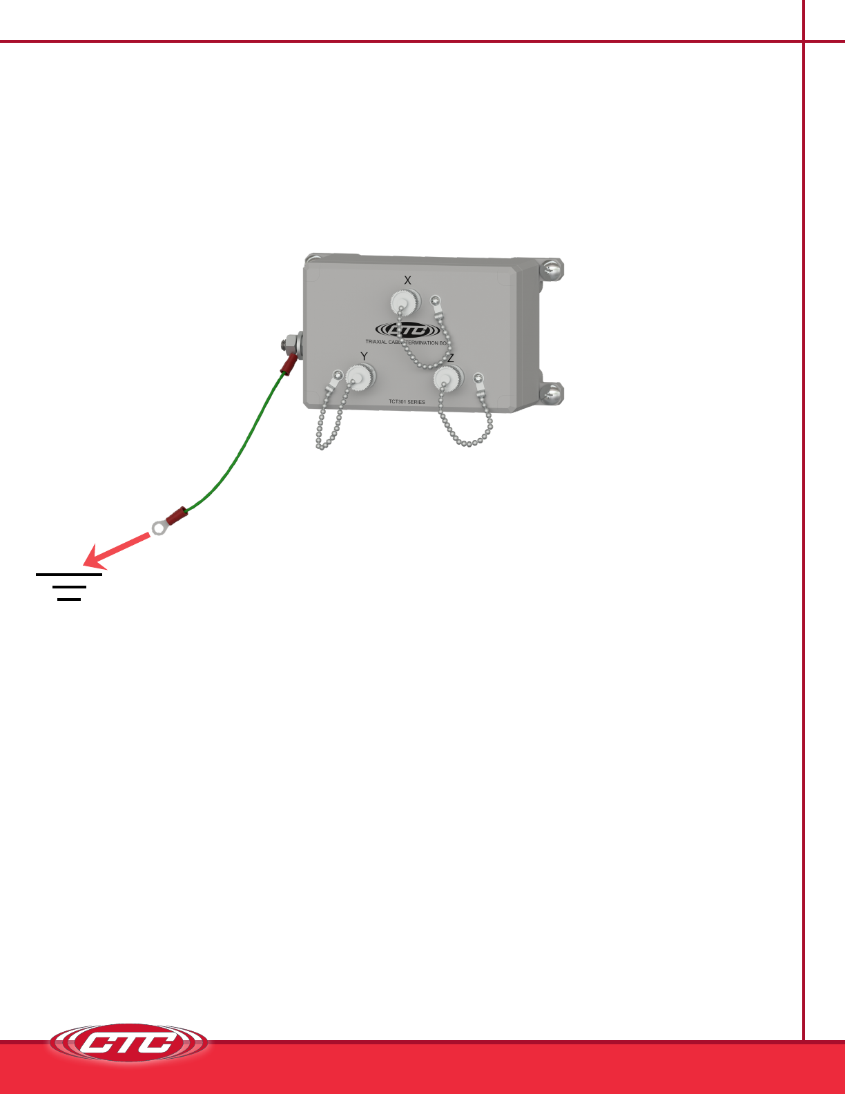
G
Optional grounding is available on the TCT301 Series. Select the “with ground
lug” option (TCT301G) when ordering if external grounding is desired.
A. Mounting to Earth Ground
When mounting TCT301G Series Termination Boxes to earth ground (such as an
I-Beam), mount the shield ground wire using a mounting bolt through one of the
mounting brackets on the enclosure. See Figure 5 below.
Figure 5. Cable Termination Box Earth Ground
8
G
B. Mounting to Non-Grounded Structure
When mounting the TCT301G to a non-grounded structure, ensure the shield
ground wire or customer-supplied ground wire is tied to a source of earth ground.
Figure 6. Ground Wire Placement
S I
Installation of Sensors/Signal Input Cable
1. Feed blunt-cut end through the cable entry at the bottom of the enclosure.
Note: It is recommended that cables are marked on both ends.
For cord grip cable entry, take off the cord grip cover with bushing and run cable
through it then into the enclosure, hand-tighten cord grip cover to base to prevent
damage of cord grip.
9
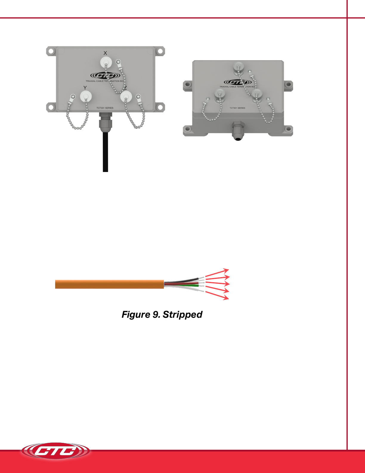
1. Strip outer jacket of cable back 1¼ in. and remove all of the shielding.
2. Separate the internal wires from the shield.
3. Strip red and black insulation back ¼ in.
Figure 8. Bottom View with
Cord Grips Installed
Figure 7. Front View
Figure 9. Stripped Wire
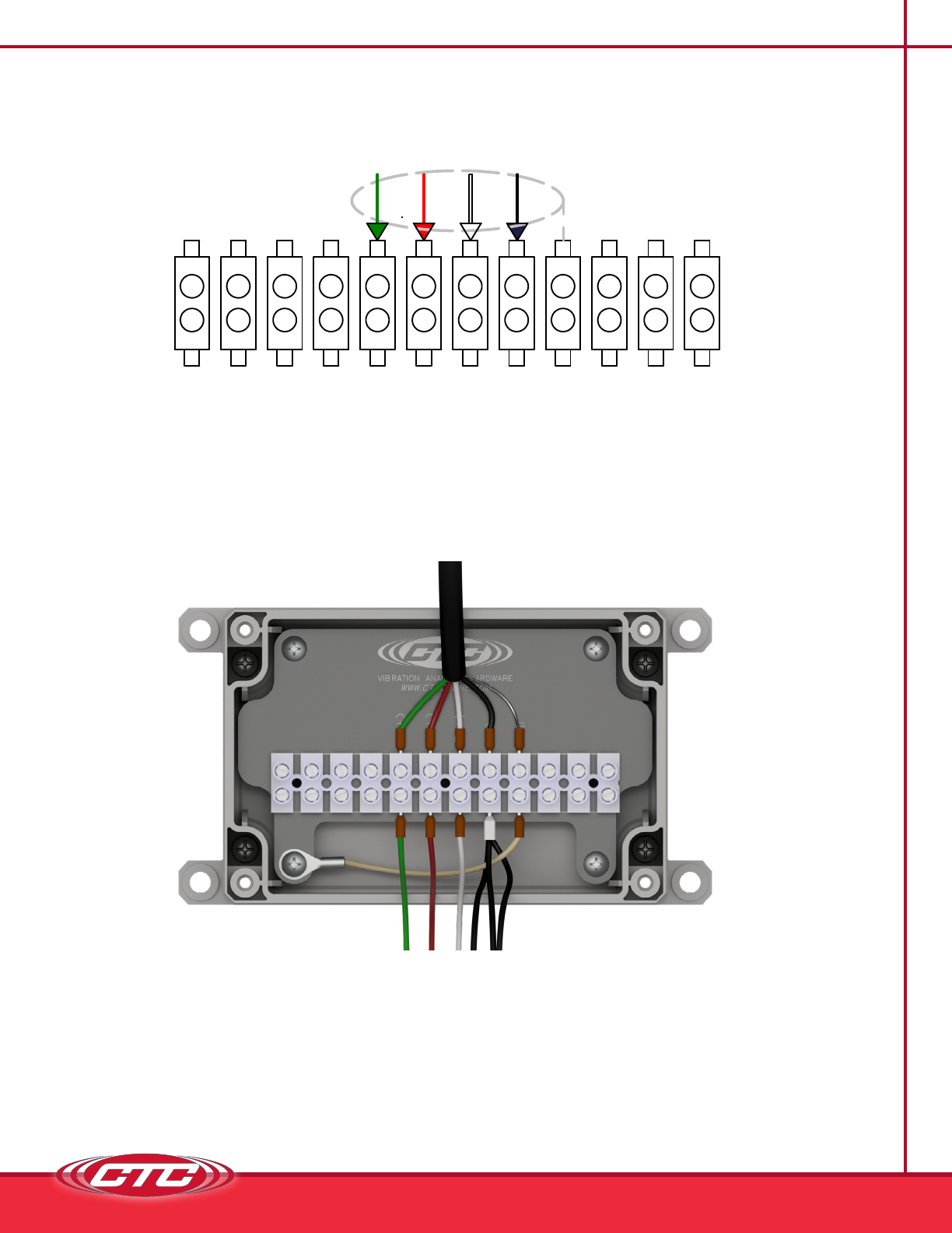
4. While viewing the rear of the panel, locate the appropriate channel. Using a mini
flathead screwriver, loosen the three screws for the channel and insert the wires
into the termination block. Orientation is as follows:
a. Green insulated conductor wire (X) is connected to the rst channel used.
b. Red insulated conductor wire (Y) is connected to the second channel.
c. White insulated conductor wire (Z) is connected to the third channel used.
d. Black insulated conductor wire is connected to (-) and must be applied to
each channel.
e. Shielddrainwireisconnectedtoground(GND)andneedsonlyonetermination.
Tighten the screw on each wire to hold it in place.
(-) Common
Shield / Drain Wire
(+) Channel Y
(+) Channel X
(+) Channel Z
10
S I
Figure 10. Field Wiring for Four-Conductor Triaxial Sensor Inputs
E
NSIONS
E
SHEET
Sensor Inputs
Green = Positive X Axis
Red = Positive Y Axis
White = Positive Z Axis
Black = Common
Grey = Shield (Ground)
SENSOR #1
Inputs
E
NSIONS
E
SHEET
Sensor Inputs
Green = Positive X Axis
Red = Positive Y Axis
White = Positive Z Axis
Black = Common
Grey = Shield (Ground)
SENSOR #1
This manual suits for next models
1
Table of contents


