CTI-CRYOGENICS 8510 Manual

C
HELIX TECHNOLOGY CORPORATION
-
TI CRYOGENICS
HELIX TECHNOLOGY CORPORATION
http://www.helixtechnology.com
8510 High-Voltage Compressor
(For Use with On-Board High-Vacuum Pumps)
Installation, Operation and Service
Instructions
8040265
Rev. P (3/97)

The information in this document is believed to be accurate and reliable. However,
Helix Technology Corporation, cannot accept any financial or other responsibilities that may
result from the use of this information. No warranties are granted or extended by this document.
Helix Technology Corporation reserves the right to change any or all
information contained herein without prior written notice. Revisions may be issued at the time of
such changes and/or deletions.
Any duplication of this manual or any of its parts without expressed written permission from
Helix Technology Corporation is strictly prohibited.
Any correspondence regarding this document should be forwarded to:
Helix Technology Corporation
Mansfield Corporate Center
Nine Hampshire Street
Mansfield, Massachusetts 02048-9171 U.S.A.
Telephone: (508) 337-5000
FAX: (508) 337-5464
The following Helix Technology Corporation trademarks and service marks may appear in this
document:
CTI-Cryogenics®GUTS®
Cryo-Torr®Cryodyne®
Cryogem®Cryogenerator®
On-Board® Helix®
RetroFast®
Value Line™RetroEase®
FastRegen™TurboPlus®
TurboLink™
ThinLine™
All other trademarks or registered trademarks are the property of their respective holders.
Copyright© 2000 Helix Technology Corporation Printed in U.S.A.

8510 High-Voltage Compressor (For Use With On-Board High-Vacuum Pumps)
P/N 8040265 iii
C
HELIX TECHNOLOGY CORPORATION
-
TI CRYOGENICS
Table of Contents
Section 1 - Introduction
General . . . . . . . . . . . . . . . . . . . . . . . . . . . . . . . . . . . . . . . . . . . . . . . . . . . . . . . . . . . 1-1
Installation, Operation and Service Instructions . . . . . . . . . . . . . . . . . . . . . . . . . . . 1-1
Section 2 - Inspection
Packaging of the System . . . . . . . . . . . . . . . . . . . . . . . . . . . . . . . . . . . . . . . . . . . . . 2-1
The Compressor . . . . . . . . . . . . . . . . . . . . . . . . . . . . . . . . . . . . . . . . . . . . . . . . . . . . 2-1
Section 3 - Installation
Compressor Installation . . . . . . . . . . . . . . . . . . . . . . . . . . . . . . . . . . . . . . . . . . . . . . 3-2
Preparing the Compressor . . . . . . . . . . . . . . . . . . . . . . . . . . . . . . . . . . . . . . . . . 3-2
Assembling the Compressor Input-Power Cable . . . . . . . . . . . . . . . . . . . . . . . . 3-3
Electrical Preparation of Compressor Control Module . . . . . . . . . . . . . . . . . . . 3-4
Cooling Water: Preparation . . . . . . . . . . . . . . . . . . . . . . . . . . . . . . . . . . . . . . . . 3-4
Cooling Water: General Considerations . . . . . . . . . . . . . . . . . . . . . . . . . . . . . . 3-5
Cooling Water: Flow and Pressure Requirements . . . . . . . . . . . . . . . . . . . . . . . 3-7
Cooling Water: Temperature Rise . . . . . . . . . . . . . . . . . . . . . . . . . . . . . . . . . . . 3-8
Oil Circuit Stabilization . . . . . . . . . . . . . . . . . . . . . . . . . . . . . . . . . . . . . . . . . . . 3-9
Connecting the Compressor to the Cryopump . . . . . . . . . . . . . . . . . . . . . . . . . . . . . 3-9
Electrical Connection of Compressor . . . . . . . . . . . . . . . . . . . . . . . . . . . . . . . . . . 3-10
8510 High-Voltage Compressor Electrical Phase Check and Automatic
ON/OFF Control . . . . . . . . . . . . . . . . . . . . . . . . . . . . . . . . . . . . . . . . . . . . . . . . . . 3-11
System Phase Input Checkout Procedure . . . . . . . . . . . . . . . . . . . . . . . . . . . . 3-11
Automatic ON/OFF Control of the Compressor Using the On-Board
Setpoint Relays . . . . . . . . . . . . . . . . . . . . . . . . . . . . . . . . . . . . . . . . . . . . . . . . 3-11
Multipump Installation . . . . . . . . . . . . . . . . . . . . . . . . . . . . . . . . . . . . . . . . . . . . . 3-12
Section 4 - Maintenance Procedures
Scheduled Maintenance . . . . . . . . . . . . . . . . . . . . . . . . . . . . . . . . . . . . . . . . . . . . . . 4-1
Removing the Compressor Adsorber . . . . . . . . . . . . . . . . . . . . . . . . . . . . . . . . . 4-2
Installing the Compressor Adsorber . . . . . . . . . . . . . . . . . . . . . . . . . . . . . . . . . 4-3
Unscheduled Maintenance . . . . . . . . . . . . . . . . . . . . . . . . . . . . . . . . . . . . . . . . . . . . 4-4
Suggested Unscheduled Maintenance Equipment . . . . . . . . . . . . . . . . . . . . . . . 4-4
Adding Helium Gas . . . . . . . . . . . . . . . . . . . . . . . . . . . . . . . . . . . . . . . . . . . 4-4
Helium Circuit Decontamination . . . . . . . . . . . . . . . . . . . . . . . . . . . . . . . . . 4-6
Cryopump Decontamination Procedures . . . . . . . . . . . . . . . . . . . . . . . . . . . 4-6
Compressor Decontamination Procedures . . . . . . . . . . . . . . . . . . . . . . . . . . 4-8
Priming the Compressor Oil System . . . . . . . . . . . . . . . . . . . . . . . . . . . . . . 4-9

8510 High-Voltage Compressor (For Use With On-Board High-Vacuum Pumps)
iv P/N 8040265
C
HELIX TECHNOLOGY CORPORATION
-
TI CRYOGENICS
Table of Contents (continued)
Appendix A - Customer Support Centers
Appendix B - Troubleshooting Procedures
Appendix C - Electrical Schematic for 8510 High-Voltage Compressor
Appendix D - Components in the Electrical Control Module of 8510
High-Voltage Compressor
Appendix E - Compressor Flow Diagram
Appendix F - Multiple Cryopump Installation with Single 8510 High-Voltage
Compressor
Figures
Figure 1-1: 8510 High-Voltage Compressor: Front and Side Views . . . . . . . . 1-2
Figure 1-2: 8510 High-Voltage Compressor . . . . . . . . . . . . . . . . . . . . . . . . . . . 1-5
Figure 3-1: Block Diagram for 8510 High-Voltage Compressor Installation . . 3-1
Figure 3-2: Removing Compressor Pump Shipping Supports . . . . . . . . . . . . . . 3-2
Figure 3-3: Preparing the 8510 High-Voltage Compressor Control Module . . 3-6
Figure 3-4: Model 8510 High-Voltage Compressor Cooling Water Flow and
Pressure Requirements . . . . . . . . . . . . . . . . . . . . . . . . . . . . . . . . . . . 3-7
Figure 3-5: 8510 High-Voltage Compressor Water Discharge
Temperature Increase (°F) . . . . . . . . . . . . . . . . . . . . . . . . . . . . . . . . 3-9
Figure 3-6: 8510 High-Voltage Compressor Installation . . . . . . . . . . . . . . . . 3-13
Figure 4-1: Connecting/Disconnecting the Adsorber Self-sealing Couplings . . 4-2
Figure C-1: 8510 (High Voltage) Compressor Schematic . . . . . . . . . . . . . . . . . C-2
Figure D-1: Components in the Electrical Control Module of 8510
High-Voltage Compressor . . . . . . . . . . . . . . . . . . . . . . . . . . . . . . . D-3

8510 High-Voltage Compressor (For Use With On-Board High-Vacuum Pumps)
P/N 8040265 v
C
HELIX TECHNOLOGY CORPORATION
-
TI CRYOGENICS
Table of Contents (continued)
Figure E-1: 8510 High-Voltage Compressor Flow Diagram . . . . . . . . . . . . . . . E-1
Figure F-1: Typical Multiple Cryopump Installation with Single 8510
High-Voltage Compressor . . . . . . . . . . . . . . . . . . . . . . . . . . . . . . . . F-1
Tables
Table 1-1: Compressor Dimensions P/N 8031400G002 . . . . . . . . . . . . . . . . . . 1-2
Table 1-2: Power Requirements (Steady-State Conditions) . . . . . . . . . . . . . . . 1-2
Table 1-3: General Specification . . . . . . . . . . . . . . . . . . . . . . . . . . . . . . . . . . . . 1-3
Table 2-1: 8510 Carton Contents . . . . . . . . . . . . . . . . . . . . . . . . . . . . . . . . . . . . 2-1
Table 3-1: 8510 High-Voltage Compressor Power Specifications . . . . . . . . . . 3-6
Table 3-2: Setpoint Relay Connections . . . . . . . . . . . . . . . . . . . . . . . . . . . . . . 3-11
Table A-1: Customer Support Centers . . . . . . . . . . . . . . . . . . . . . . . . . . . . . . . . A-2
Table B-1: Compressor Troubleshooting Procedures . . . . . . . . . . . . . . . . . . . . B-2
Table D-1: Legend for Figure D-1 . . . . . . . . . . . . . . . . . . . . . . . . . . . . . . . . . . . D-1

8510 High-Voltage Compressor (For Use with On-Board High-Vacuum Pumps)
P/N 8040265 1-1
C
HELIX TECHNOLOGY CORPORATION
-
TI CRYOGENICS
Section 1 - Introduction
General
The manual provides instructions for installing, operating and servicing the
8510 High-Voltage Compressor, P/N 8031400G002 (380-460 volts). If you
are installing or operating an On-Board High-Vacuum System you should
also have available the On-Board High-Vacuum Pump Manual that applies
to your particular system:
• 8040215 On-Board 8 and 8F High-Vacuum Pumps
• 8040233 On-Board 10 and 400 High-Vacuum Pumps
The manuals for a system cover two basic components: the high-vacuum
pump and the compressor. Each manual outlines the details necessary for
installation, operation and servicing of that component. A manual is
shipped with each system component (high-vacuum pump and
compressor). When you purchase a system, you will receive the two
manuals necessary for system installation, plus a loose-leaf binder with
index tab separators, allowing you to compile a complete indexed system
notebook.
Installation, Operation and Service Instructions
Installation, Operation and Service Instructions for your 8510 High-
Voltage Compressor provide easily accessible information. All personnel
with installation, operation, and servicing responsibilities should become
familiar with the contents of these instructions to ensure high quality, safe,
reliable performance. Unit must be wired by an authorized electrician in
accordance with the national electrical code, ANSI/NFPA 70-1987, as well
as the local codes.

Introduction
1-2 P/N 8040265
C
HELIX TECHNOLOGY CORPORATION
-
TI CRYOGENICS
Figure 1-1: 8510 High-Voltage Compressor: Front and Side Views
Table 1-1: Compressor Dimensions P/N 8031400G002
Location Compressor Dimension Inches
(mm)
A 19.52 max.
(496 mm)
B21.50 max.
(546 mm)
C 24.24 max.
(616 mm)
D 2.30
(58 mm)
Table 1-2: Power Requirements (Steady-State Conditions)
Compressor Volts Hz Phase Full Load
Current
(Amps)
Ooperating
Voltage Range
(Volts)
Maximum
Phase Run
Current
(Amps)
8510, Part No.
8031400G002 460
380 60
50 3
38
8395-506
342-457 11
11
B
A
C
D

8510 High-Voltage Compressor (For Use with On-Board High-Vacuum Pumps)
P/N 8040265 1-3
C
HELIX TECHNOLOGY CORPORATION
-
TI CRYOGENICS
Table 1-3: General Specification
Specification Description
Weight 340 lbs (154 kg) approximate
Weight
(shipping) 445 lbs (202 kg) approximate
Power
consumption 5.4 kw, nominal operating power, 6.2 kw maximum
0.8 power factor, 7.8 kva maximum
Compressor input-power
cable
(customer-supplied)
Recommended type SO-4 conductor, 600V, neoprene jacket
and 10-gauge or 4mm2 minimum wire.
Install per Figure B-1, Electrical Schematic Diagram, ensuring
compliance with all national, state and local standards.
Helium pressure Static: 195-205 psig (1345-1415 kPa) at 70 to 80°F (21 to
27°C)
Return: Normal operation: 75-85 psig (517-590 kPa) at operat-
ing temperature.
Ambient operating
temperature range 50 to 100°F (10 to 38°C)
Interface Cold head power receptacles (3): Mates with plugs on cold
head power cables.
Compressor input-power termination: Connects with #10
(5mm) ring terminals.
Gas-supply connector: 1/2-inch self-sealing coupling
Gas-return connector: 1/2-inch self-sealing coupling
Remote control receptacle 24VAC, 150ma: Mates with J5 con-
nector P/N MS3106A-20, supplied by CTI-CRYOGENICS.
Adsorber service schedule Replace every three years.
Cooling water requirements 70°F water supply, 2.5 gpm, 14 psid (pressure drop: water inlet
to water outlet).
The pressure value does not consider discharge back-pressure
conditions.
Maximum/minimum water requirements
Maximum outlet temperature 100°F (38°C)
Minimum inlet temperature 40°F (4°C)
Maximum inlet pressure 100 psig

Introduction
1-4 P/N 8040265
C
HELIX TECHNOLOGY CORPORATION
-
TI CRYOGENICS
This compressor has been designed to operate with water having a pH
value of 6.0 to 8.0 and a calcium carbonate concentration of less than 75
parts per million (typical municipal drinking water quality). For
applications of lower pH or greater hardness, water conditioning may be
necessary.

8510 High-Voltage Compressor (For Use with On-Board High-Vacuum Pumps)
P/N 8040265 1-5
C
HELIX TECHNOLOGY CORPORATION
-
TI CRYOGENICS
Figure 1-2: 8510 High-Voltage Compressor
1
319
4
5
6
7
810
14
18
15
17
16
911
1. Compressor Power ON/OFF Switch (with ON lamp)
2. On-Board System Power Switch (with ON Lamp)
3. Oil sight glass
4. Cooling water output.
5. Cooling water input.
6. Helium gas-return connector self-sealing coupling.
7. Helium gas-supply connector self-sealing coupling.
8. Compressor overload reset.
9. Voltage selector switches (S3).
10. Voltage selector switches (S2).
11. Elapsed time meter (ETM).
12. Cold head power circuit breakers (CB2 and CB3).
13. Cold head power cable receptacles (J2, J3, and J4).
14. Input power cable receptacle (J1).
15. Helium return pressure gauge.
16. Helium gas charge fitting and valve.
17. Safety interlock.
18. System power ON/OFF switch circuit breaker (CB1).
19. System remote control receptacle (J5) (Jumper plug
installed).
2
LEGEND
12 13

8510 High-Voltage Compressor (For Use with On-Board High-Vacuum Pumps)
P/N 8040265 2-1
C
HELIX TECHNOLOGY CORPORATION
-
TI CRYOGENICS
Section 2 - Inspection
Packaging of the System
The On-Board High-Vacuum Pump System is packaged in three separate
cartons. Listed below are the contents of each carton, as they relate to these
two system applications. Note that an Installation, Operation, and Service
Manual is included in cartons for the high-vacuum pump and compressor.
Each manual covers the component packaged in that carton.
When installing an On-Board High-Vacuum Pump System,
CTI-CRYOGENICS recommends that as you unpack a component:
perform an inspection and the necessary tasks for system installation for
the component according to the manual included with the component. Final
system installation and operation will be performed following procedures
in the On-Board 8/8F or 10 and 400 Cryopump Manual (No. 8040215 or
8040233 respectively).
The Compressor
On receipt, remove the 8510 High-Voltage Compressor from its shipping
carton and inspect the compressor for evidence of damage as described in
this Section.
1. Unpackage and remove the compressor from its shipping
carton.
2. Check the carton contents. It should contain:
a. 8510 High-Voltage Compressor.
Table 2-1: 8510 Carton Contents
Carton Label On-Board 8/8F, 10 And 400 High-vacuum
Pump System Carton Contents Manual
Included
On-Board On-Board 8/8F Cryopumps 8040215
On-Board On-Board 10 and 400 Cryopumps 8040233
Compressor 8510 High-Voltage Compressor 8040265
Accessories Installation and Scheduled Maintenance
Tool Kit and Accessories,
P/N 8032040G014
—

Inspection
2-2 P/N 8040265
C
HELIX TECHNOLOGY CORPORATION
-
TI CRYOGENICS
b. Two barbed fittings for compressor cooling water connec-
tions.
c. Compressor remote start connector.
d. Input power connector.
e. Oil prime manifold, P/N 8018129.
f. 8510 High-Voltage Compressor Manual P/N 8040265.
8510 High-Voltage Compressor (For Use with On-Board High-Vacuum Pumps)
P/N 8040265 3-1
C
HELIX TECHNOLOGY CORPORATION
-
TI CRYOGENICS
Section 3 - Installation
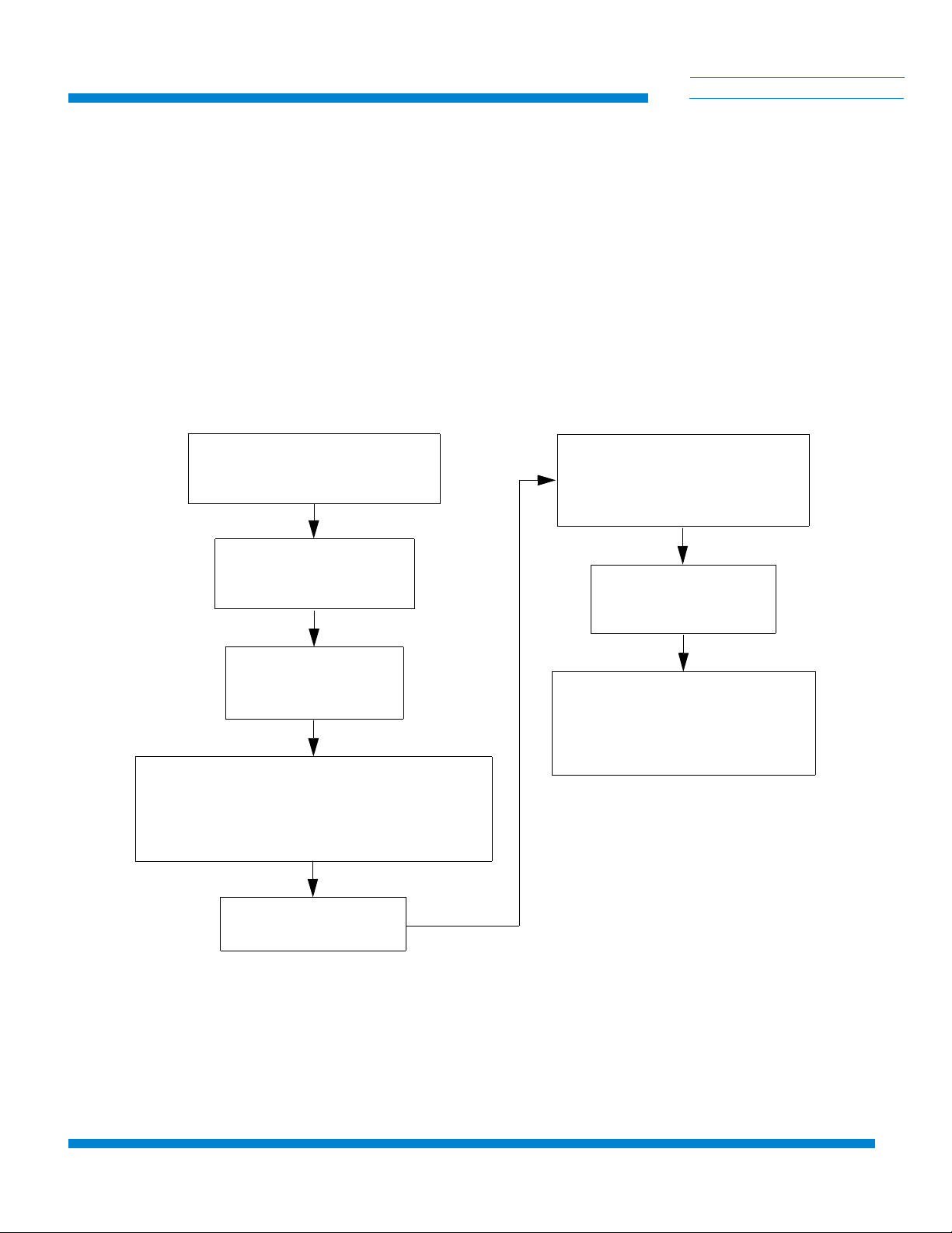
Figure 3-1: Block Diagram for 8510 High-Voltage Compressor Installation
Removing Compressor Pump
Shipping Supports
(Refer to Page 3-2)
Assemble Compressor
Input-Power Cable
(Refer to Page 3-3)
Setting Voltage
Tap Switches
(Refer to Page 3-4)
Cooling Water Connections to Compressor
Cooling Water PH Factors and Conservation
Cooling Water Flow and Pressure Requirements
Cooling Water Temperature Rise
(Refer to Page 3-4)
Oil Circuit Stabilization
(Refer to Page 3-9)
Helium Gas Return and
Supply Connections
Verifying Helium Static Pressure
(Refer to Page 3-9)
Connecting Relay Connector Pins
Programming Relay #1 to the
Cryopump Function
(Refer to Page 3-11)
Making Electrical
Connections
(Refer to Page 3-10)

Installation
3-2 P/N 8040265
C
HELIX TECHNOLOGY CORPORATION
-
TI CRYOGENICS
Compressor Installation
Installation of your compressor requires no special tools other than those
supplied in the Installation and Scheduled Maintenance Tool Kit.
Preparing the Compressor
1. After removing the compressor front panel, refer to Figure 3-2 and
remove the front two compressor pump shipping supports.
a. Remove the front two nuts and red flat washers that secure
the compressor pump tightly in position.
NOTE: Retain the two red flat washers for use during shipment.
b. Remove the two rubber grommets that are in the package
attached to the compressor: install them, flat side up, onto
the front two mounting posts.
c. Reinstall the two nuts and screw them down flush with the
tops of the mounting posts.
d. Replace the compressor front panel.
Figure 3-2: Removing Compressor Pump Shipping Supports
Compressor Base
Red Flat Washer
Hex Head Nut
Red Flat Washer
Hex Head Nut
Rubber Grommets

8510 High-Voltage Compressor (For Use with On-Board High-Vacuum Pumps)
P/N 8040265 3-3
C
HELIX TECHNOLOGY CORPORATION
-
TI CRYOGENICS
Assembling the Compressor Input-Power Cable
To supply input power to the compressor requires the fabrication of a 600-
volt power cable that has an SO-4 conductor, 600-volt rating neoprene
jacket and 10-gauge or 4 mm2wire. Proceed as follows:
WARNING
Do not connect the compressor to the power source at this time. All of
the preparation must be completed and all panels reinstalled before elec-
trically connecting the compressor.
Unit must be wired by an authorized electrician in accordance with the
national Electrical Code, ANSI/NFPA 70-1996, as well as the local
codes. This shall include installation of a readily accessible disconnect
device into the fixed wiring supplying power.
An insulated safety grounding conductor that is identical in size, insula-
tion material and thickness to the circuit supply conductors, except that it
is green with or without one or more yellow stripes is to be installed as
part of the branch circuit which supplies the unit or system. The ground-
ing conductor described is to be connected to the equipment grounding
conductor of the supply circuit.
1. Prepare the input power cable by terminating each of the four
conductors with a #10 ring terminal. Follow the terminal
manufacturer’s instructions to insure proper crimping.
2. Disassemble the electrical terminal enclosure cover, mounted on
the control module, as shown in Figure 3-3. Remove the two screws
securing the cover and lift it off.
3. If necessary, back off strain relief screws.
4. Thread input power cable end up through the strain relief into the
enclosure.
5. Attach the three conductors onto the appropriate terminals of the
terminal block; attach the ground conductor to the ground stud of
the enclosure. See Figure 3-3. Check that there are no bare conduc-
tors exposed.
6. Tighten all terminals to 18-22 in.-lbs. torque.
7. Tighten down screws on strain relief.

Installation
3-4 P/N 8040265
C
HELIX TECHNOLOGY CORPORATION
-
TI CRYOGENICS
CAUTION
Ensure that strain relief is tightened down on the outer insulation of
the input power cable and that the cable does not slide.
8. Remount the terminal enclosure cover and secure with two screws.
9. Refer to Electrical Connection of Compressor for correct phasing
checkout procedure.
WARNING
Insure that the ground wire is returned to the equipment grounding con-
ductor of the circuit supplying the receptacle.
Electrical Preparation of Compressor Control Module
1. Refer to Table 1-2, for electrical power requirements. Then,
using a voltmeter, measure the phase-to-phase voltage from the
power source.
2. Prepare the compressor voltage selector switches S2 and S3 as
required in accordance with Figure 3-3.
Cooling Water: Preparation
If flexible water hose connections are used, install the barbed fittings
supplied with the compressor on the input and output connections:
1. Apply a light coating of standard plumbing thread sealant on
the barbed fitting threads.
2. Tighten fittings on 1/2-inch FPT input and output connections. DO
NOT OVERTIGHTEN.
3. Connect flexible hoses to the fittings and secure with hose clamps.
If hard piping is desired, install the water lines directly onto the compressor
1/2-inch FPT input and output connections. DO NOT OVERTIGHTEN.
CAUTION
Check water connections for leaks.

8510 High-Voltage Compressor (For Use with On-Board High-Vacuum Pumps)
P/N 8040265 3-5
C
HELIX TECHNOLOGY CORPORATION
-
TI CRYOGENICS
Cooling Water: General Considerations
NOTE: Adjust your water flow to maintain an optimum discharge water
temperature of 80° with a minimum input pressure of 7 psi. For detailed
water requirements, see below.
1. Cooling water must meet flow and pressure requirements as
indicated in the following subsections.
2. Cooling water having a pH value of 6.0 to 8.0 and a calcium-car-
bonate concentration of less than 75 ppm, the quality of typical
municipal drinking water, is acceptable. If the cooling water has a
pH value lower than 6.0 or a calcium-carbonate concentration
higher than 75 ppm, water conditioning may be required.
3. To conserve water, the cooling water should be shut off when the
compressor is not running.
CAUTION
If cooling water below 45°F (7°C) is allowed to run through the
compressor while the compressor is not operating, the compressor oil
will change viscosity and thicken, causing the compressor to overheat
and shut off at startup. In this event, repeatedly restart the compressor
and allow it to run until it has shut off several times. The oil
temperature will rise and thereby allow continuous compressor
operation.

Installation
3-6 P/N 8040265
C
HELIX TECHNOLOGY CORPORATION
-
TI CRYOGENICS
Figure 3-3: Preparing the 8510 High-Voltage Compressor Control Module
4. Drain and purge water from the compressor before shipping it back
to the factory or subjecting it to freezing conditions. Purge water
from the compressor by blowing compressed air, regulated to 30 to
40 psig (200 to 275 kPa) into the compressor output connection and
allowing water to exit from the water input connection.
Table 3-1: 8510 High-Voltage Compressor Power Specifications
Compressor
Configuration Frequency
(Hz) Voltage Voltage Selector Switch Setting
S2 S3
P/N 8031400G002
380/460VAC, 50/60 Hz 50 342-405
406-457 2
2* 3
4
60 395-450
451-506 2
2* 3
4
*Factory setting
1. Terminal Block 1
2. Terminal Block Cover Screws
3. Cold Head Power Connector (J12)
4. Cold Head Power Connector (J11)
5. Cold Head Power Connector (J10)
6. System Power Switch (CB1)
7. Cold Head Circuit Breaker (CB3)
8. Cold Head Circuit Breaker (CB2
9. On-Board Circuit Breaker (CB7)
10. On-Board Circuit Breaker (CB7)
11. Heater Circuit Breaker (CB5)
12. Heater Circuit Breaker (CB4)
13. Elapsed time meter
14. Voltage selector switch (S2)
15 Voltage selector switch (S3)
16. System Control Interface Connector (J5)
12 11 10 987
1
6
5
4
3
2
16
15
14
13
8510 High-Voltage Compressor (For Use with On-Board High-Vacuum Pumps)
P/N 8040265 3-7
C
HELIX TECHNOLOGY CORPORATION
-
TI CRYOGENICS
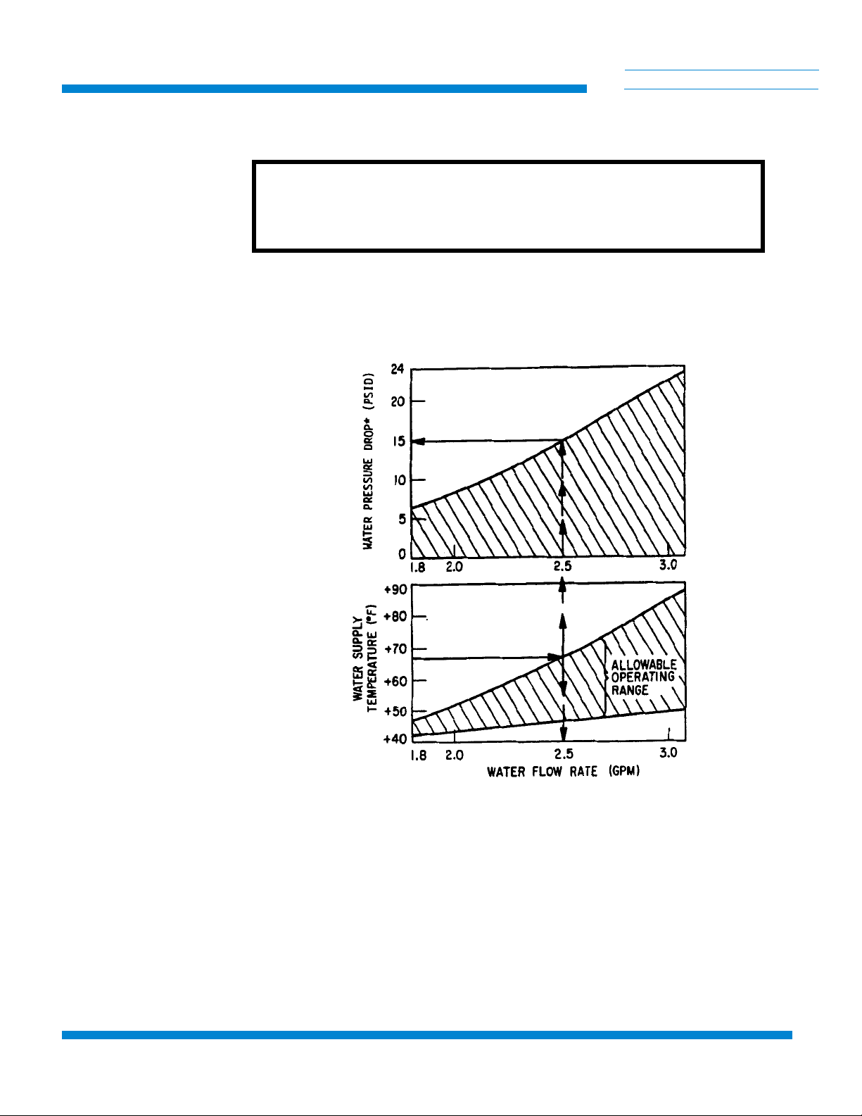
Cooling Water: Flow and Pressure Requirements
CAUTION
If your water supply pressure falls below 7 psig due to back pressure,
the compressor will overheat and shut down.
Use the two graphs in Figure 3-4, to determine the minimum acceptable
cooling water supply pressure at different flow rates and temperatures.
Find the minimum pressure:
Figure 3-4: Model 8510 High-Voltage Compressor Cooling Water Flow and Pressure
Requirements
1. Determine the temperature variation of the cooling water.
Allow a ±10°F to the present water temperature if a variation
cannot be ascertained. Plot the high and low temperatures on
the vertical axis of the lower graph.
The example describes cooling water that varies between 45°F and 67°F.
NOTE: Without
consideration of back
pressure.

Installation
3-8 P/N 8040265
C
HELIX TECHNOLOGY CORPORATION
-
TI CRYOGENICS
2. Determine the optimum water flow rate by drawing a horizontal
line from the upper temperature variation figure on the lower graph
to the upper curve of the allowable operating range indicated by
cross-hatching. Draw a line from this intersecting point straight
down to the horizontal axis to find the optimal flow rate.
The example shows a solid arrow extending from 67°F and intersecting the
allowable operating range. Dashed arrows pointing downward indicate a
water flow rate of 2.5 gallons per minute.
3. Determine the cooling water supply pressure drop by drawing a line
straight up from the flow rate in the lower graph to the upper graph.
At the point at which this line intersects the upper graph, draw a
line leftward to the vertical axis and find the water supply pressure
drop.
The example shows dashed arrows extending from the lower to the upper
graph. On the upper graph the dashed arrows intersect the graph curve at
approximately 15 psig.
4. Determine the total cooling water supply pressure drop by adding
the pressure drop determined from the graph to the water back pres-
sure at the installation site.
Cooling Water: Temperature Rise
CAUTION
The temperature of the cooling water as it leaves the compressor should
not exceed 100°F.
Use the graph in Figure 3-5 to determine the rise in cooling water
temperature as it passes through the compressor. The recommended
discharge temperature for the compressor is 80° F. This information is used
by plant engineering personnel to determine cooling water requirements.
Find the temperature rise:
1. Draw a vertical line upward from the horizontal axis of the
graph at the water flow rate determined from the previous
section, until it hits the graph curve.
The example shows dashed arrows pointing upward to the graph curve
from 2.5 gpm on the water flow rate axis.
Table of contents
Popular Air Compressor manuals by other brands

CLAS
CLAS OM 1170 manual

RIDGID
RIDGID OF60150HB Operator's manual

Waeco
Waeco mobitronic PC-100-12/P operating instructions

California Air Tools
California Air Tools 10020DC-22060 owner's manual

KAESER KOMPRESSOREN
KAESER KOMPRESSOREN EPC-2-G Series Assembly and operating manual

Atlas Copco
Atlas Copco AUTOMAN AC40 instruction manual


Gude
Gude 400/10/50 N operating instructions

California Air Tools
California Air Tools 2010A owner's manual

KAESER KOMPRESSOREN
KAESER KOMPRESSOREN SIGMA CONTROL SMART M114 Operator's manual

Vmac
Vmac VR70 installation manual

Bristol
Bristol A Series Installation & service instructions

Bambi
Bambi VT75 Operator's handbook