Vmac VR70 User manual

System V900079
2004.5 - 2005 GMC C4500 - 5500
6.6L Duramax Diesel
www.vmacair.com
VR70 UNDERHOOD
AIR COMPRESSOR
INSTALLATION MANUAL


VMAC – Vehicle Mounted Air Compressors
Toll Free: 1-800-738-8622
Fax: 1-250-740-3201 1
Installation Manual for VMAC
System V900079
General Motors 2004.5 – 2005
Duramax Diesel
C4500 – 5500
General Information..................................................................... 3
Before You Start ....................................................................... 3
Special Installation Notes ......................................................... 4
Part 1: Preparing for Installation............................................... 5
1.0 Preparing for Installation .................................................... 5
1.1 Dual Alternator Trucks........................................................ 7
Part 2: Installing the Main Bracket and Compressor.............. 8
2.1 Installing the Main Bracket ................................................. 8
2.2 Installing the Cooler............................................................ 11
2.3 Connecting the Hoses ........................................................ 13
Part 3: Installing the Tank and Hoses....................................... 14
3.1 Installing the Tank and Brackets ........................................ 14
3.2 Filling the System with Oil .................................................. 16
3.3 Completing the Installation ................................................. 17
Part 4: Installing the Control Components .............................. 19
4.1 Installing the Control Components ..................................... 20
4.2 Connecting the In-cab Wiring ............................................. 21
4.3 Connecting the Underhood Wiring ..................................... 22
4.4 Connecting the Power Supply Wire ................................... 24
4.5 Completing and Testing the Installation ............................. 24
Part 5: Finishing the Installation................................................ 26
5.1 Before Starting the Engine Checklist ................................. 26
5.2 After Starting the Engine Checklist..................................... 27
5.3 Setup, Performance Testing and Adjustments................... 28
5.4 System Identification and Warnings................................... 29
5.5 Auxiliary Air Receiver ......................................................... 30
Accessory Products from VMAC............................................... 31

VMAC – Vehicle Mounted Air Compressors
Toll Free: 1-800-738-8622
Fax: 1-250-740-3201
2
Document #1930076
Installation Manual for VMAC System V900079
General Motors 2004.5 – 2005 Duramax Diesel C4500 - 5500
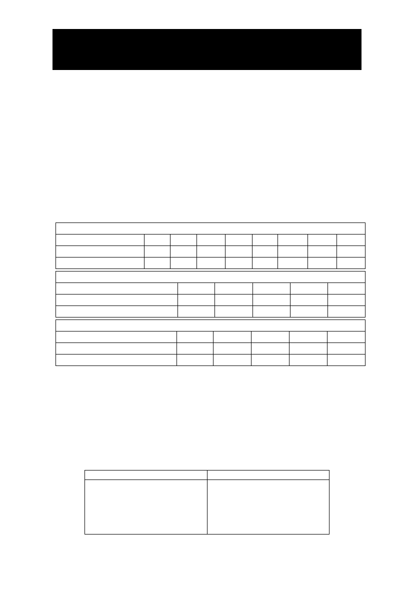
Changes and Revisions
Version Revision Details Revised by/date Approved Implemented
00 Original manual IB Nov 06 2004 SM/SC 26 Jan 2005 26 Jan 2005
a Electrical changes IB 29 Jan 2005 SM 02 Feb 2005 04 Feb 2005
b Content revisions IB 12 Feb 2005 SC 10 Mar 2005 14 Mar 2005
c Main bracket mount IB 15 Sep 2005 SM 20 Sep 2005 23 Sep 2005
d ECN 06-179 main brkt bolt IB 13 Aug 2006
e ECN 06-239 main brkt chng IB 23 Nov 2006 TG 29 Nov 2006 01 Dec 2006
f ECN 06-265 comp. mount IB 21 Dec 2006 TG 21 Dec 2006 27 Dec 2006
Important Information
The information in this manual is intended for certified VMAC installers who
have been trained in installation procedures and for people with mechanical
trade certification who have the tools and equipment to properly and safely
perform the installation. Do not attempt this installation if you do not have the
appropriate mechanical training, knowledge and experience.
Follow all safety precautions for underhood mechanical work. Any grinding,
bending or restructuring operations for correct fit in modified vehicles must
follow standard shop practices.
These instructions are a general guide for installing this system on standard
production trucks and do not contain information for installation on non-
standard trucks. This system may not fit special order models or those which
have had other changes without additional modifications. If you have
difficulty with the installation, contact VMAC.
The VMAC warranty form is located at the back of this manual. This
warranty form must be completed and mailed or faxed to VMAC at the time
of installation for any subsequent warranty claim to be considered valid.
To order parts, contact your VMAC dealer. Your dealer will ask for the
VMAC serial number, part number, description and quantity. To locate your
nearest dealer, call 1-800-738-8622.
Copyright 2007
All trademarks used in this manual are the property of the respective copyright holder.
The contents of this manual may not be reproduced in any form without the express written
permission of VMAC, 1333 Kipp Road, Nanaimo, BC V9X 1R3.
Printed in Canada

VMAC – Vehicle Mounted Air Compressors
Toll Free: 1-800-738-8622
Fax: 1-250-740-3201 3
General Information
Before You Start
Read this manual before attempting installation so that you can
familiarize yourself with the components and how they fit on the
vehicle. Open the package, unpack the components and identify the
parts. Identify variations for different model years or OEM options
that are listed in the manual.
All fasteners must be torqued to specifications. Use manufacturers
torque values for OEM fasteners. Apply Loctite 242 or equivalent on
all engine-mounted fasteners. Torque values are with Loctite applied
unless otherwise specified.
STANDARD GRADE 8 NATIONAL COARSE THREAD
Size 1/4 5/16 3/8 7/16 1/2 9/16 5/8 ¾
Foot-pounds (ft-lb) 9 18 35 55 80 110 170 280
Newton meter (N•m) 12 24 47 74 108 149 230 379
STANDARD GRADE 8 NATIONAL FINE THREAD
Size 3/8 7/16 1/2 5/8 ¾
Foot-pounds (ft-lb) 40 60 90 180 320
Newton meter (N•m) 54 81 122 244 434
METRIC CLASS 10.9
Size M8 M10 M12 M14 M16
Foot-pounds (ft-lb) 19 41 69 104 174
Newton meter (N•m) 25 55 93 141 236
Hose Coding
Different frame designations will affect the tank mounting position.
You may have to move the tank rearward from the standard position
on your application. If you must move the tank, the lines may be too
short. If this is the case, measure the hose shortfall and order a
Hose Extender Kit. The following table shows the color code used
by VMAC to define the different hose diameters.
Hose Diameter Colour-Coded Label
1/4 inch
5/16 inch
1/2 inch
5/8 inch
3/4 inch
1 inch
Yellow
Orange
Blue
Blue
Green
Green

VMAC – Vehicle Mounted Air Compressors
Toll Free: 1-800-738-8622
Fax: 1-250-740-3201
4
Special Installation Notes
The following special tools are required:
•36 mm 12 point 1/2 inch drive socket for removing the OEM
crankshaft bolt
•crankshaft locking tool (GM #J-44643) or VMAC equivalent
(Part #5900010)
•VMAC crankshaft pin extraction tool (Part #5900076) or
equivalent
The following additional materials are recommended:
•assorted sizes of fireproof protective plastic loom
•assorted lengths of nylon tie-straps

VMAC – Vehicle Mounted Air Compressors
Toll Free: 1-800-738-8622
Fax: 1-250-740-3201 5
Part 1: Preparing for Installation
1.0 Preparing for Installation
Preparation for installation is very important. Missing an item can
cause problems in the installation or even damage to components.
Check off each item as it is completed so that you do not miss any
preparation steps.
□Disconnect the batteries.
□Drain the coolant.
□Disconnect the MAF sensor wire from the air cleaner and
remove the complete air intake assembly, complete with rubber
air intake pipe, air ducting and the plastic intake resonator
chamber from the top of the engine.
□On trucks with dual alternators, remove the plastic centering lug
from the back of the air cleaner housing.
□Remove the plastic inner fender liner on the passenger side.
□Disconnect the hoses from the coolant expansion tank,
disconnect the level sensor connector and remove the tank.
□Remove the air cleaner base mounting plate and the air cleaner
support bracket.
□Remove the top radiator hose.
□Remove the upper fan shroud. Remove the mount bolts from the
lower fan shroud, but leave the shroud in position.
□Remove the fan using the appropriate fan wrench.
□Remove the passenger side intercooler tube and hoses.
□Remove and discard the heater hose and metal connector pipe
from the lower radiator hose.

VMAC – Vehicle Mounted Air Compressors
Toll Free: 1-800-738-8622
Fax: 1-250-740-3201
6
□Disconnect the fuel inlet and outlet banjos from the fuel
management module, remove the module and move it out of the
way. Remove the rubber washers, plastic spacers, mounting
bolts and banjo fitting seals so they will not get lost.
□Remove and discard the rubber hose that connects between the
fuel rail and the module.
□Remove the OEM belt.
□Remove all wire harness retainers from the OEM alternator
mount bracket.
□Remove the alternator (passenger side on dual alternator trucks)
and keep the bolts.
□Remove the OEM idler and tensioner from the alternator mount
bracket.
□Remove the OEM alternator mount bracket.
□Remove the rock guard from under the front of the truck (if
equipped).
□Install a crankshaft locking tool, remove the crank pulley bolt and
remove the crank pulley. If you are using the VMAC tool:
•put the socket on the nut
•put the single-pin end of the tool on the front of the pulley with
the locking tool hanging straight down
•put a short extension and long flex-bar on the socket
•turn the engine until the pin on the tool makes contact and the
tool jams against the protruding center-piece of the cross-
member under the front of the engine.
□Remove the crankshaft pin. If you are using the VMAC extraction
tool:
•fit the split end of the tool (on the end of the shaft) over the
crankshaft pin and tap downward with the slide-hammer to
make sure that it is seated correctly
•tighten the pinch bolt securely
•use the hammer action of the slider in an upward motion to
remove the pin from the crankshaft

VMAC – Vehicle Mounted Air Compressors
Toll Free: 1-800-738-8622
Fax: 1-250-740-3201 7
□Install the replacement crankshaft/harmonic balancer locating pin
and tap it home using a brass drift and a small hammer. Ensure
that the head of the pin is aligned with the crankshaft. You may
have to twist it into position (Figure 1.1).
High-strength
crank pin
Figure 1.1
□Apply a light wipe of oil to the inside of the OEM crank pulley and
install the pulley back onto the crankshaft.
1.1 Dual Alternator Trucks
□Loosen the top mounting bolt on the driver’s side alternator and
remove the lower mounting bolts.
□Install the supplied bracket under the alternator and insert the
mounting bolts.
□Push the alternator upward and tighten all the bolts.

VMAC – Vehicle Mounted Air Compressors
Toll Free: 1-800-738-8622
Fax: 1-250-740-3201
8
Part 2: Installing the Main Bracket
and Compressor
2.1 Installing the Main Bracket
□Remove the belt tensioner assembly from the VR main bracket.
□Remove the plastic caps and remove the four M10 x 85 mm low
profile socket head screws from the bracket. Place the bracket in
position on the front of the engine.
□Insert the two M10 x 85 low profile socket bolts and thread the
two OEM 10 mm flange nuts onto the two studs. Thread all
fasteners in just enough to hold the bracket in place (Figure 2.1).
Check the fit of the bracket against the engine to make sure that
it fits flat and has no obstructions, tighten the bolts evenly and
then torque them to specifications.
Install OEM
back idler here
M10 x 85 mm
socket head bolts
(one behind the VR tensioner
)
OEM 10 mm nuts
Install the OEM
tensioner here
Figure 2.1

VMAC – Vehicle Mounted Air Compressors
Toll Free: 1-800-738-8622
Fax: 1-250-740-3201 9
□Apply Loctite and install the VR tensioner, the OEM belt
tensioner and one OEM back idler (Figure 2.1).
□Install the alternator.
□Place the VR crank pulley in position with the two roll pins on
both sides of the counter balance weight of the OEM pulley
(Figure 2.2).
Position the roll pins here
Figure 2.2
□Apply Loctite and thread the M18 x 100 mm center bolt with
OEM washer into the crankshaft. Install an engine-locking tool
and torque the center bolt to manufacturer’s specifications
(usually about 250 ft-lbs (340 N.m).
□On single alternator trucks, install the supplied replacement for
the OEM belt (Figure 2.3). On dual alternator trucks, install the
OEM belt (Figure 2.4).
□Remove the bolts holding the compressor to the packaging base.
□Attach the straight end of the short 1/2 inch hose to the fitting on
the side of the compressor, route the hose over the top of the
compressor behind the clutch assembly and tighten the fitting.

VMAC – Vehicle Mounted Air Compressors
Toll Free: 1-800-738-8622
Fax: 1-250-740-3201
10
OEM ribbed idler
OEM tensioner
Alternator
OEM back idler
A
/C
P/S
Fan
OEM crank pulley
Figure 2.3
OEM RIBBED IDLER
OEM TENSIONER
ALTERNATOR
A
LTERNAT
OR
OEM BACK IDLER
A/C
P/S
FAN
OEM CRANK PULLE
Y
Figure 2.4
□Remove the inlet control valve and immediately cover the
opening on the compressor to prevent contamination.
□Place the compressor on the mounting bracket and install two
M8 x 25 mm bolts in the front holes and one M8 x 20 mm bolt in
the rear hole, complete with serrated washers.

VMAC – Vehicle Mounted Air Compressors
Toll Free: 1-800-738-8622
Fax: 1-250-740-3201 11
□Tighten the bolts evenly, making sure that they do not bottom-out
in the holes and that the compressor is properly secured to the
bracket, then torque them to specifications.
□Install the VR drive belt (Figure 2.5).
VR70 Tensioner
VR70 Ribbed idler
VR70 Compressor
VR70 Idler
Crankshaft pulle
y
Figure 2.5
2.2 Installing the Cooler
□Remove the strap and the support bracket from the cooler
assembly (Figure 2.6).
□Move the lower fan shroud up to provide clearance and position
the cooler (from under the truck) on the inside of the U-channel
cross-member where the rock guard was located. Insert the two
3/8 x 1 inch flange lock bolts through the rock guard mounting
holes into the cooler.
□Place the cooler support bracket on the two bolts with the center
hole facing toward the front of the vehicle, install flange lock nuts
on the bolts and torque to specifications.

VMAC – Vehicle Mounted Air Compressors
Toll Free: 1-800-738-8622
Fax: 1-250-740-3201
12
□Pass the support strap through the hole in the top of the cooler
back plate, around the U-channel frame and through the support
bracket. Install a flat washer and 5/16 inch nut and tighten, then
install a second 5/16 inch nut as a lock.
Su
pp
ort bracket
Cooler oil hose fittings
T
o eng
i
ne
To radiator
Cooler
suppor
t
strap
Figure 2.6
□Cut the lower radiator hose to length (Figure 2.7) and install each
hose section back to the original positions, between the radiator
and the cooler and the engine and the cooler.
To engine
To Radiator
To coolant
expansion tank
Heater hose
connection
7 1/2”
12”
A
C
1”
D B
1”
Figure 2.7

VMAC – Vehicle Mounted Air Compressors
Toll Free: 1-800-738-8622
Fax: 1-250-740-3201 13
2.3 Connecting the Hoses
□Connect the straight end of the long 1/2 inch hose to the 90
degree fitting on the cooler but do not tighten the fitting. Route
the hose under the compressor and along the passenger side
frame back to the transfer case cross-member.
□Connect the 90 degree end of the 1/2 inch hose from the
compressor to the passenger side fitting on the cooler and
tighten the fitting.
□Connect the straight end of the 3/4 inch hose to the fitting on the
back of the compressor but do not tighten the fitting. Route the
hose from the compressor to the same position on the frame as
the 1/2 inch hose from the cooler.
No part of the 3/4 inch hose can be higher than the
compressor. If it is, the system will not function
correctly.
□Connect the heater return from the lower radiator hose to the
heater hose using the supplied hose barbs and hose, cutting the
hose to length as required for a good fit.

VMAC – Vehicle Mounted Air Compressors
Toll Free: 1-800-738-8622
Fax: 1-250-740-3201
14
Part 3: Installing the Tank and
Hoses
3.1 Installing the Tank and Brackets
The tank will mount to the passenger side frame rail between the leaf
spring shackle and the transmission skid plate (Figure 3.1).
1/4” line
5/16” lin
e
3/4” hose fitting
1/2” hose fitting
C-clamp
Tube clamp
Pinch bolt
Oil filter
Bracket mount
Tank bracket
6”
6”
Figure 3.1
□Remove the oil filter from the front of the tank, fill it with
compressor oil, cover it and place it out of the way.
□Place the tank on a work bench with the front (oil filter end) of the
tank to your right.

VMAC – Vehicle Mounted Air Compressors
Toll Free: 1-800-738-8622
Fax: 1-250-740-3201 15
□Loosen the two 1/4 inch pinch bolts from the C-clamps. Expand
the clamps slightly, slide them over the front of the tank with the
bolt heads facing away from you and position them about 6
inches from each end of the tank, with the flats of the clamps on
the work bench.
□Rotate the tank so that the directional arrow on the end of the
tank is parallel to the work bench and points away from you,
check the distance of each C-clamp from the ends of the tank
and tighten the pinch bolts so that the clamps grip the tank
securely.
□Apply Loctite pipe thread sealant and install a 90 degree fitting to
the outlet on the tank. Tighten it to about the four O’clock
position for testing, then reposition or replace as required for
operational connections.
□Thread the 1/4 and 5/16 inch fittings on the steel lines to the
matching fittings on the back end of the tank, but do not tighten
the fittings. Route the lines along the top of the tank across the
two C-clamps.
□Route the hose ends of the 1/4 and 5/16 inch lines through the
gap formed by the tank bracket and the angled support and
position a tank bracket under each C-clamp.
□Place the tank brackets and bracket mounts on the frame, one in
front of the spring shackle and one just behind the transfer case
skid plate. Install the bolts and nuts but do not tighten them.
□Place insulated tube clips over the steel lines with the mounting
holes downward and the flat side toward the frame and align
them with the top mounting holes on each C-clamp.
□Apply Loctite and insert 5/16 x 1/2 inch bolts through the tube
clip, the upper C-clamp holes and into the tank bracket. Repeat
for the lower C-clamp holes and tighten all the bolts.
□Tighten the 1/4 and 5/16 inch fittings on the back of the tank.

VMAC – Vehicle Mounted Air Compressors
Toll Free: 1-800-738-8622
Fax: 1-250-740-3201
16
□Lift the tank assembly and support it in position so the two tank
mounts sit on the bottom of the frame rail with the bend on the
outside of the frame. Loosely connect the 3/4 and 1/2 inch lines
to the tank to establish position.
□Position a bracket mount over each tank bracket and install bolts
and nuts through each bracket, adjust the position of the tank as
required and tighten.
□Route the 1/4 and 5/16 inch hoses to the compressor.
□Tighten the 1/2 and 3/4 inch hose connections on the tank,
compressor and cooler, adjusting the positions as necessary to
provide a good fit and clearance.
□Secure all hoses together and in place using plastic ties at
regular intervals along the frame, other harnesses or the cross-
member so that they do not touch the exhaust or moving parts.
□Apply a light coating of oil to the filter gasket and install the filter
on the tank. Tighten an additional 3/4 turn after the gasket
contacts the base.
3.2 Filling the System with Oil
□Remove the protective covering from the compressor and pour
the supplied compressor oil into the compressor, turning the
center of the compressor clutch clockwise to speed oil flow into
the tank.
You must use VMAC compressor oil in this system.
Failure to use this special oil will result in damage to the
compressor and will void your warranty.
□Allow 5 minutes for the oil to drain into the tank, then check the
level at the sight glass at the front of the tank. Continue adding
oil until the level is correct.
Do not overfill the system.
!
!

VMAC – Vehicle Mounted Air Compressors
Toll Free: 1-800-738-8622
Fax: 1-250-740-3201 17
3.3 Completing the Installation
□Place the inlet control valve in position and thread in the two
mounting bolts nearest the engine.
□Place the supplied fuel control module bracket in position over
the remaining inlet control valve holes and thread in the
remaining bolts (Figure 3.2). Torque all the bolts to
specifications.
Figure 3.2
□Mount the fuel control module onto the new mount plate with the
OEM fasteners, making sure that you install all the rubber and
plastic mount parts. Leave the mount bolts loose until all of the
fittings have been attached.
□Install the supplied banjo fitting to the top fitting on the fuel
control module. Point it toward the firewall and tighten the fitting.
□Install the straight hose connector fitting to the banjo fitting on
the steel fuel rail (originally connected to the top of the module)
with the hose connector pointing up and toward the driver side of
the truck.

VMAC – Vehicle Mounted Air Compressors
Toll Free: 1-800-738-8622
Fax: 1-250-740-3201
18
□Cut a suitable length of fuel hose to connect between the banjo
fitting on the fuel rail and the top fitting on the fuel control
module. Leave enough length so that the line bends in a smooth
curve without crimping.
□Install the intercooler tube, making sure that the tube is pushed
in all the way and that the clamps are securely tightened. Do not
apply any lubricant to the metal pipe or rubber connectors.
□Install the air cleaner/coolant fill tank support bracket and coolant
expansion tank.
□On dual alternator trucks, install the supplied positioning bracket
to the driver’s side air cleaner mount to reposition the air cleaner
away from the alternator. Once installed, the air cleaner should
be touching the firewall and provide about 1/2 inch clearance
between the air cleaner and the alternator
□Connect the MAF sensor plug and the coolant bottle-wiring plug.
□Mark the aluminum fan clutch and blade assembly to ensure
correct orientation, then separate the fan clutch from the fan
blade assembly.
□Place the supplied fan blade spacing ring on to the fan clutch.
Ensure the recessed side of the ring is mating with the fan
clutch, align the fan blade assembly onto the spacer and install
the supplied M8 x 30 mm bolts and washers. Use Loctite and
torque to specification.
□Install the large fan nut spacer into the existing fan clutch. Check
for correct seating of the aluminum fan spacer between the fan
blade and clutch assembly, then install the fan assembly.
□Install the upper fan shroud and top radiator hose.
□Connect hoses to the coolant fill tank, then fill the cooling system
with coolant to the correct level.
□Install all other OEM parts removed previously. Check all the
hoses, lines and OEM harnesses to make sure that they are
secured and protected.
Other manuals for VR70
24
Table of contents
Other Vmac Air Compressor manuals

Vmac
Vmac Underhood 70 User manual

Vmac
Vmac V900104 User manual

Vmac
Vmac UNDERHOOD 40 Series User manual

Vmac
Vmac V900170 User manual

Vmac
Vmac VR70 User manual

Vmac
Vmac VR70 User manual

Vmac
Vmac H400005 Installation instructions

Vmac
Vmac G300004 User manual

Vmac
Vmac UNDERHOOD 150 User manual

Vmac
Vmac VR70 User manual
Popular Air Compressor manuals by other brands

AWELCO
AWELCO PLASMA 40 user manual

Ingersoll-Rand
Ingersoll-Rand R30 manual

EINHELL
EINHELL TH-AC 190/6 OF Original operating instructions

Coltri Compressors
Coltri Compressors ERGO Use and maintenance manual

Sealey
Sealey Power PRODUCTS SA1565 instructions

Sullair
Sullair LS-20T Operator's manual and parts list