CubiScan 125 User manual

CubiScan 125 Operations and Technical Manual
CubiScan®and the Quantronix logo are registered trademarks of Quantronix, Inc.
Scanning New Dimensions™, Qbit™, QbitWIN™, and The FreightWeigh System™ are trademarks of Quantronix, Inc.
Windows®is a registered trademark of Microsoft Corporation.
CubiScan® software and firmware are protected by international and domestic copyrights.
CubiScan®150 measurement products are protected by one or more of U.S. Patents Re42,430 and D490,328 and
foreign patents.
CubiScan®110 measurement products are protected by one or more of U.S. Patent Re42,430 and foreign patents.
CubiScan®125 measurement products are the subject of U.S. Patent 8,928,896. Another U.S. patent is pending.
CubiScan®225 measurement products are protected by one or more U.S. patents, refer to U.S. Patent 9435637.
This document and website Copyright©2017 by Quantronix, Inc. All rights reserved.
CAUTION
The CubiScan 125 should only be serviced by qualified personnel.
Observe precautions for handling electrostatic sensitive devices when setting
up or operating the CubiScan 125.
WARNING Disconnect all power to the CubiScan 125 before servicing or making any
connections.

FCC Compliance Statement for American Users
This device complies with Part 15 of the FCC rules. Operation is subject to the following two conditions: 1) This device
may not cause harmful interference, and 2) This device must accept any interference received, including interference
that may cause undesired operation.
EMI Compliance Statement for Canadian Users
This digital apparatus does not exceed the Class A limits for radio noise emissions from digital apparatus set out in the
Radio Interference Regulations of the Canadian Department of Communications.
Le présent appareil numérique n'émet pas de bruits radioélectriques dépassant les limites applicables aux appareils
numériques de la Classe A prescrites dans le Règlement sur le brouillage radioélectrique édicté par le ministère des
Communications du Canada.
Limited Warranty Quantronix New Product
StatementofWarranty.Quantronix,Inc.’s,warrantyobligationsarelimitedtothetermssetforthbelow:Quantronix(hereinafterreferred
toasthe“Seller”)warrantsthatitsnewproductisinaccordancewithSeller’spublishedspecifications(orthoseagreeduponwithBuyerin
writing)atthetimeofsaleorleaseandthatitisfreefromnon‐cosmeticdefectsinmaterialsandworkmanshipundernormalusefora
periodofone(1)yearfromthedateofsaleorthecommencementdateunderawrittenequipmentleaseorrentalagreement(the“Warranty
Period”).IfahardwaredefectarisesandavalidclaimisreceivedwithintheWarrantyPeriod,atitsoption,Sellerwilleither(i)repairthe
hardwaredefectatnocharge,usingneworrefurbishedreplacementparts,or(ii)exchangetheproductordefectivepart(s)withaproduct
orpart(s)thatareneworwhichhasbeenmanufacturedfromneworserviceableusedpartsandisatleastfunctionallyequivalenttothe
originalproductorpart,or(iii)refundthepurchasepriceoftheproductafterBuyerhasreturnedtheproducttoSeller.Forpurposesofthis
warrantyagreement,“Buyer”shallmeanandreferto(i)thepartywhichoriginally–whetherfromSellerdirectly,orfromanauthorized
distributor,agentorresellerwhoisauthorizedbySeller–purchases,orleasesunderawrittenequipmentleaseorrentalagreement,the
Seller’sproductwhichisthesubjectofthiswarranty,or(ii)anysubsequentpurchaserortransfereethatacquiresvalidtitle t o t h e
equipmentwithintheWarrantyPeriod.
Intheeventoftheoccurrenceofaclaimunderthiswarranty,theBuyershallhavethirty(30)daystonotifySellerinwritingofthenature
andspecificsoftheclaimeddefect;provided,however,thatanyandallclaimsmustbereceivedbeforetheexpirationoftheWarrantyPeriod.
FailuretonotifySellerwithinsuchtimeperiodshallvoidthiswarranty.Anyclaimofawarrantieddefectissubjecttoinspectionandanalysis
bySeller,priortoand/orafterBuyershipstheproducttoSeller,toconclusivelyidentifyorconfirmthenatureandcauseoffailureand
applicationofthiswarranty.IntheeventthatthedefectordamageisexcludedfromwarrantytheSellermayatitsoptioneither(i)provide
Buyerwithaquotetomakeanysuchrepairsorreplacementswhicharenotcoveredunderthiswarranty,or(ii)giveBuyertwenty(20)days
topayforreturnshippinganduponreceiptreturntheproducttoBuyer.IfBuyerfailstopayforreturnshippingaftertwenty(20)days’
noticeandafterrepairsaremadeorwarrantycoverageisdeterminednotapplicable,Sellermaydisposeoforscraptheproduct.
Thisisafactorywarrantyandanydefectivecomponents,mechanicalorelectrical,willberepairedorreplaced,atthediscretionand
authorizationofSeller,atSeller’sfacilitiesinUtah.ItshallbetheBuyer’sresponsibilitytoreturnthefaultyequipmentorcomponentsto
E171537
ITE

SelleratBuyer’sexpenseaswellaspayforallreturnshipping.AllreplacedorexchangedpartsbecomespropertyofSeller.Buyershallfirst
receivewrittenconfirmationtoshiptheproductbeforesendingit.Writtenconfirmationtoshipisnotaguaranteethatthedefectordamage
totheproductiscoveredbythiswarranty.Sellerisnotobligatedtopayforlabor,material,orservicechargesinvolvedintheremoval,
return,orinstallationofequipmentorcomponents.Sellerreservestherighttoincorporateimprovementsinmaterialanddesignofits
productswithoutnoticeandisnotobligatedtoincorporatethesameimprovementsinequipmentpreviouslymanufactured.
ExclusionsandLimitations.Thislimitedone(1)yearwarrantyisapplicableexclusivelytooriginalequipmentproductsandcomponents
thatweremanufacturedbySeller.Selleralsowarrantsitsreplacementparts,subjecttothetermsandconditionssetforthherein,forthe
lesserperiodofninety(90)daysfromthedateofdeliveryoruntiltheexpirationoftheoriginalwarranty,whicheverisgreater.Sellerdoes
notwarrant,foranypurpose,anyexternalaccessories,orintegratedparts,includingbutnotlimitedtocomputers,controllersand/or
barcodescanners,thataremanufacturedbyanothermanufacturerandsoldunderaseparatelabel,eveniftheyarepackagedorsoldwith
Seller’sproduct.Seller’sobligationandliabilityunderthiswarrantyisexpresslylimitedtorepairorreplacement(atitsoption)ofthe
warrantiedequipmentorcomponentswithintheWarrantyPeriod.ApurchasebyBuyerofequipmentthatithadfirstleasedorrentedshall
notstartanewWarrantyPeriod.Sellerdoesnotwarrantthattheoperationoftheproductwillbeuninterruptedorerror‐free.
Thiswarrantyshallnotapplytoequipmentorcomponentswhichhas/have:
1.Beenthesubjectofanaccident,orrepairsormodificationsattemptedormadeandnotauthorizedbySeller.
2.Beenusedwithincompatibleproducts.
3.Beenoperatedunderabnormalconditions,excessiveheatorcold,highlycorrosiveenvironments,orinanunintendedmanner.
4.NotbeenoperatedormaintainedinaccordancewithSeller’sinstructions.
5.Beensubjecttomisuseorabuse,negligenthandling,improperinstallation,accident,damagebyfire,flood,snow,ice,waterorother
liquiddamage,lightning,abnormalelectricalconditionand/orpowersurge,earthquake,orotheractofGodoreventsoutsideof
Sellerscontrol.
6.Hadserialnumbersaltered,defacedorremoved.
7.Beenoperatedbeyondcapacity.
8.NotbeenmanufacturedbySellerincludingparts,accessories,orcomponentswhichhavebeenintegratedinto,usedalongsideof,or
inconjunctionwithaproductmanufacturedbySeller.
TOTHEEXTENTPERMITTEDBYLAW,THISWARRANTYANDTHEREMEDIESSETFORTHABOVEAREEXCLUSIVEANDINLIEUOF
ALLOTHERWARRANTIES,REMEDIESANDCONDITIONS,WHETHERORALORWRITTEN,STATUTORY,EXPRESSORIMPLIED.TO
THEMAXIMUMEXTENTALLOWEDBYLAW,SELLERSPECIFICALLYDISCLAIMSANYANDALLSTATUTORYORIMPLIED
WARRANTIES,INCLUDING,WITHOUTLIMITATION,WARRANTIESOFMERCHANTABILITY,FITNESSFORAPA RT IC ULARPURPOSE
ANDWARRANTIESAGAINSTHIDDENORLATENTDEFECTS.IFSELLERCANNOTLAWFULLYDISCLAIMSTATUTORYORIMPLIED
WARRANTIESTHENTOTHEEXTENTPERMITTEDBYLAW,ALLSUCHWARRANTIESSHALLBELIMITEDINDURATIONTOTHE
DURATIONOFTHISEXPRESSWARRANTY ANDTOREPAIRORREPLACEMENTSERVICEASDETERMINEDBYSELLERINITSSOLE
DISCRETION.ThisstatementsetsforththefullextentofSeller’sliabilityforbreachofanywarrantyordeficiencyinconnectionwiththe
saleoruseoftheproduct.Noemployee,representativeorresellerofSellerisauthorizedtochangethiswarrantyinanywayorgrantany
otherwarranty.
EXCEPTASPROVIDEDINTHISWARRANTYANDTOTHEEXTENTPERMITTEDBYLAW,SELLERISNOTRESPONSIBLEFORDIRECT,
INDIRECT,SPECIAL,PUNITIVE,INCIDENTALORCONSEQUENTIALDAMAGESRESULTINGFROMANYBREACHOFWARRANTYOR
CONDITION,ORUNDERANYOTHERLEGALTHEORY,INCLUDINGBUTNOTLIMITEDTOLOSSOFUSE;LOSSOFREVENUE;LOSSOF
ACTUALORANTICIPATEDPROFITS(INCLUDINGLOSSOFPROFITSONCONTRACTS);LOSSOFTHEUSEOFMONEY;LOSSOF
ANTICIPATEDSAVINGS;LOSSOFBUSINESS;LOSSOFOPPORTUNITY;LOSSOFGOODWILL;LOSSOFREPUTATION;LOSSOF,DAMAGETO
ORCORRUPTIONOFDATA;ORANYINDIRECTORCONSEQUENTIALLOSSORDAMAGEHOWSOEVERCAUSEDINCLUDINGTHE
REPLACEMENTOFEQUIPMENTANDPROPERTY,ANDANYCOSTSOFRECOVERING,PROGRAMMING,ORREPRODUCINGANYPROGRAM
ORDATASTOREDORUSEDWITHSELLERPRODUCTS.BUYERWAIVESTHERIGHTTOSEEKTOTALCOMBINEDDAMAGESFROMSELLER
INEXCESSTOTHATWHICHWASPAIDTOSELLERANDSELLERSHALLBELIMITEDFROMANYANDALLCLAIMSRELATEDTOTHIS
WARRANTYTOBENOMORETHANWHATWASPAIDTOSELLERFORTHENEWPRODUCT.
CONSUMERPROTECTIONLAWS.FORCONSUMERSWHOARECOVEREDBYCONSUMERPROTECTIONLAWSORREGULATIONSIN
THEIRCOUNTRYOFPURCHASEOR,IFDIFFERENT,THEIRCOUNTRYOFRESIDENCE,THEBENEFITSCONFERREDBYTHISWARRANTY
AREINADDITIONTOALLRIGHTSANDREMEDIESCONVEYEDBYSUCHCONSUMERPROTECTIONLAWSANDREGULATIONS.Some
countries,statesandprovincesdonotallowtheexclusionorlimitationofincidentalorconsequentialdamagesorexclusionsorlimitations
onthedurationofimpliedwarrantiesorconditions,sotheabovelimitationsorexclusionsmaynotapplytoyou.Thiswarrantygivesyou
specificlegalrights,andyoumayalsohaveotherrightsthatvarybycountry,stateorprovince.

What’s New in Version 1.3?
UpdatedSections
•Updated terminology and images to be consistent with the latest firmware version
•Added a firmware log, see “Appendix B Firmware Log” on page 86
•Deleted the Communications Protocol and made it a separate document
Thisdocumentwascreatedwiththepurposeofprovidingthemostaccurateandcompleteinformation.Ifyou
havecommentsorsuggestionsforimprovingthismanual,contactQuantronixat[email protected].
ManualupdatedJuly12,2017.

Table of Contents
Chapter 1 Product Description . . . . . . . . . . . . . . . . . . . . . . . . . . . . . . . . . . . . . 1
Specifications . . . . . . . . . . . . . . . . . . . . . . . . . . . . . . . . . . . . . . . . . . . . . . . . . 2
Chapter 2 Setup . . . . . . . . . . . . . . . . . . . . . . . . . . . . . . . . . . . . . . . . . . . . . . . . . . . . . 5
Unpacking . . . . . . . . . . . . . . . . . . . . . . . . . . . . . . . . . . . . . . . . . . . . . . . . . . . 5
Placement. . . . . . . . . . . . . . . . . . . . . . . . . . . . . . . . . . . . . . . . . . . . . . . . . . . . 6
Assembling the CubiScan 125 . . . . . . . . . . . . . . . . . . . . . . . . . . . . . . . . . . . . . 7
Attaching the Top Sensor Support . . . . . . . . . . . . . . . . . . . . . . . . . . . . . . .8
Attaching the Height Sensor Cable. . . . . . . . . . . . . . . . . . . . . . . . . . . . . . . 9
Removing the Shipping Material . . . . . . . . . . . . . . . . . . . . . . . . . . . . . . . 12
Placing the Glass Platform . . . . . . . . . . . . . . . . . . . . . . . . . . . . . . . . . . . . 13
Connecting Power . . . . . . . . . . . . . . . . . . . . . . . . . . . . . . . . . . . . . . . . . . . . 14
Turning On the CubiScan 125. . . . . . . . . . . . . . . . . . . . . . . . . . . . . . . . . . . . 14
Connecting to a Computer or Network (Optional) . . . . . . . . . . . . . . . . . . . . 15
Connecting to a Computer via Ethernet . . . . . . . . . . . . . . . . . . . . . . . . . . 16
Connecting to a Computer via USB . . . . . . . . . . . . . . . . . . . . . . . . . . . . . 19
Connecting to a Computer via Serial (RS-232-C) . . . . . . . . . . . . . . . . . . . 21
Installing Qbit (Optional) . . . . . . . . . . . . . . . . . . . . . . . . . . . . . . . . . . . . . . . 21
Setup Checklist. . . . . . . . . . . . . . . . . . . . . . . . . . . . . . . . . . . . . . . . . . . . . . . 21
Chapter 3 Operation . . . . . . . . . . . . . . . . . . . . . . . . . . . . . . . . . . . . . . . . . . . . . . .23
Before You Begin . . . . . . . . . . . . . . . . . . . . . . . . . . . . . . . . . . . . . . . . . . . . .23
CubiScan 125 Touchscreen . . . . . . . . . . . . . . . . . . . . . . . . . . . . . . . . . . . . . .24
Touchscreen Care. . . . . . . . . . . . . . . . . . . . . . . . . . . . . . . . . . . . . . . . . . .24
Cubing and Weighing . . . . . . . . . . . . . . . . . . . . . . . . . . . . . . . . . . . . . . . . . . 25
Cubing and Weighing Using Qbit . . . . . . . . . . . . . . . . . . . . . . . . . . . . . . .25
Cubing and Weighing Using the Touchscreen . . . . . . . . . . . . . . . . . . . . . 25
Zeroing the CubiScan 125 . . . . . . . . . . . . . . . . . . . . . . . . . . . . . . . . . . . . . . . 31
Chapter 4 Configuration . . . . . . . . . . . . . . . . . . . . . . . . . . . . . . . . . . . . . . . . . . .32
System Configuration . . . . . . . . . . . . . . . . . . . . . . . . . . . . . . . . . . . . . . . . . .32
Operation . . . . . . . . . . . . . . . . . . . . . . . . . . . . . . . . . . . . . . . . . . . . . . . . .32
Units . . . . . . . . . . . . . . . . . . . . . . . . . . . . . . . . . . . . . . . . . . . . . . . . . . . .38
Ethernet . . . . . . . . . . . . . . . . . . . . . . . . . . . . . . . . . . . . . . . . . . . . . . . . . .40

Other . . . . . . . . . . . . . . . . . . . . . . . . . . . . . . . . . . . . . . . . . . . . . . . . . . . .42
Chapter 5 Calibration . . . . . . . . . . . . . . . . . . . . . . . . . . . . . . . . . . . . . . . . . . . . . .44
Before You Begin . . . . . . . . . . . . . . . . . . . . . . . . . . . . . . . . . . . . . . . . . . . . .44
Calibrating the Scale. . . . . . . . . . . . . . . . . . . . . . . . . . . . . . . . . . . . . . . . . . .45
Calibrating the Gate . . . . . . . . . . . . . . . . . . . . . . . . . . . . . . . . . . . . . . . . . . .48
Calibrating the Touchscreen. . . . . . . . . . . . . . . . . . . . . . . . . . . . . . . . . . . . .50
Calibrating the Ultrasound Sensors . . . . . . . . . . . . . . . . . . . . . . . . . . . . . . .52
Chapter 6 Maintenance . . . . . . . . . . . . . . . . . . . . . . . . . . . . . . . . . . . . . . . . . . . .58
Precautions. . . . . . . . . . . . . . . . . . . . . . . . . . . . . . . . . . . . . . . . . . . . . . . . . .58
Cleaning the Ultrasound Sensors . . . . . . . . . . . . . . . . . . . . . . . . . . . . . . . . .58
Cleaning the Gate Filters . . . . . . . . . . . . . . . . . . . . . . . . . . . . . . . . . . . . . . . 59
Removing the Controller . . . . . . . . . . . . . . . . . . . . . . . . . . . . . . . . . . . . . . .59
Chapter 7 Troubleshooting . . . . . . . . . . . . . . . . . . . . . . . . . . . . . . . . . . . . . . . . 61
No Response When You Turn Power On . . . . . . . . . . . . . . . . . . . . . . . . . . . 61
Scale Readings Are Not Accurate . . . . . . . . . . . . . . . . . . . . . . . . . . . . . . . . .62
Dimension Readings Are Not Accurate. . . . . . . . . . . . . . . . . . . . . . . . . . . . .62
Computer Error Messages . . . . . . . . . . . . . . . . . . . . . . . . . . . . . . . . . . . . . .62
About . . . . . . . . . . . . . . . . . . . . . . . . . . . . . . . . . . . . . . . . . . . . . . . . . . . . . .63
Version. . . . . . . . . . . . . . . . . . . . . . . . . . . . . . . . . . . . . . . . . . . . . . . . . . .63
Config-Audit . . . . . . . . . . . . . . . . . . . . . . . . . . . . . . . . . . . . . . . . . . . . . .65
Cal-Audit . . . . . . . . . . . . . . . . . . . . . . . . . . . . . . . . . . . . . . . . . . . . . . . . .66
Diagnostics. . . . . . . . . . . . . . . . . . . . . . . . . . . . . . . . . . . . . . . . . . . . . . . . . .68
Scale Diagnostics . . . . . . . . . . . . . . . . . . . . . . . . . . . . . . . . . . . . . . . . . . .68
Gate Diagnostics . . . . . . . . . . . . . . . . . . . . . . . . . . . . . . . . . . . . . . . . . . .69
Touchscreen Diagnostics . . . . . . . . . . . . . . . . . . . . . . . . . . . . . . . . . . . . . 74
Sensor Diagnostics . . . . . . . . . . . . . . . . . . . . . . . . . . . . . . . . . . . . . . . . . . 76
Testing . . . . . . . . . . . . . . . . . . . . . . . . . . . . . . . . . . . . . . . . . . . . . . . . . . . . . 79
Scale. . . . . . . . . . . . . . . . . . . . . . . . . . . . . . . . . . . . . . . . . . . . . . . . . . . . . 79
Gate . . . . . . . . . . . . . . . . . . . . . . . . . . . . . . . . . . . . . . . . . . . . . . . . . . . . .80
Appendix A Parts List. . . . . . . . . . . . . . . . . . . . . . . . . . . . . . . . . . . . . . . . . . . . . . . . .84
Appendix B Firmware Log . . . . . . . . . . . . . . . . . . . . . . . . . . . . . . . . . . . . . . . . . . .86

List of Figures
Figure 1 CubiScan 125. . . . . . . . . . . . . . . . . . . . . . . . . . . . . . . . . . . . . . . . . . . . . . . . . . . . . . . . . . . . . . . . 2
Figure 2 CubiScan 125 in Crate . . . . . . . . . . . . . . . . . . . . . . . . . . . . . . . . . . . . . . . . . . . . . . . . . . . . . . . . 6
Figure 3 Raised Screws at Top of Assembled CubiScan 125 . . . . . . . . . . . . . . . . . . . . . . . . . . . . . . . . . 8
Figure 4 Top Sensor Support Attached . . . . . . . . . . . . . . . . . . . . . . . . . . . . . . . . . . . . . . . . . . . . . . . . . . 9
Figure 5 Location of Height Sensor Cable . . . . . . . . . . . . . . . . . . . . . . . . . . . . . . . . . . . . . . . . . . . . . . . 9
Figure 6 Routing the Height Sensor Cable . . . . . . . . . . . . . . . . . . . . . . . . . . . . . . . . . . . . . . . . . . . . . . 10
Figure 7 Attaching the Sensor Cable Cover . . . . . . . . . . . . . . . . . . . . . . . . . . . . . . . . . . . . . . . . . . . . . 11
Figure 8 Connecting the Height Sensor Cable . . . . . . . . . . . . . . . . . . . . . . . . . . . . . . . . . . . . . . . . . . . 12
Figure 9 Foam Shipping Supports . . . . . . . . . . . . . . . . . . . . . . . . . . . . . . . . . . . . . . . . . . . . . . . . . . . . . 12
Figure 10 Cable Tie Holding Measuring Gate. . . . . . . . . . . . . . . . . . . . . . . . . . . . . . . . . . . . . . . . . . . . . 13
Figure 11 Glass Cubing and Weighing Platform . . . . . . . . . . . . . . . . . . . . . . . . . . . . . . . . . . . . . . . . . . 13
Figure 12 Connecting Power. . . . . . . . . . . . . . . . . . . . . . . . . . . . . . . . . . . . . . . . . . . . . . . . . . . . . . . . . . . 14
Figure 13 Ethernet, Serial, and USB Connectors . . . . . . . . . . . . . . . . . . . . . . . . . . . . . . . . . . . . . . . . . . 16
Figure 14 Installation Bubble. . . . . . . . . . . . . . . . . . . . . . . . . . . . . . . . . . . . . . . . . . . . . . . . . . . . . . . . . . 17
Figure 15 Device Installed Bubble . . . . . . . . . . . . . . . . . . . . . . . . . . . . . . . . . . . . . . . . . . . . . . . . . . . . . . 17
Figure 16 Installation Process Bubble. . . . . . . . . . . . . . . . . . . . . . . . . . . . . . . . . . . . . . . . . . . . . . . . . . . 17
Figure 17 Adapter is Ready to Use. . . . . . . . . . . . . . . . . . . . . . . . . . . . . . . . . . . . . . . . . . . . . . . . . . . . . . 17
Figure 18 Status Window . . . . . . . . . . . . . . . . . . . . . . . . . . . . . . . . . . . . . . . . . . . . . . . . . . . . . . . . . . . . . 18
Figure 19 General Properties Window . . . . . . . . . . . . . . . . . . . . . . . . . . . . . . . . . . . . . . . . . . . . . . . . . . 19
Figure 20 CubiScan 125 Touchscreen . . . . . . . . . . . . . . . . . . . . . . . . . . . . . . . . . . . . . . . . . . . . . . . . . . . 24
Figure 21 Measurement Display . . . . . . . . . . . . . . . . . . . . . . . . . . . . . . . . . . . . . . . . . . . . . . . . . . . . . . . 26
Figure 22 Package on Platform . . . . . . . . . . . . . . . . . . . . . . . . . . . . . . . . . . . . . . . . . . . . . . . . . . . . . . . . 27
Figure 23 Ultrasound Measurement Display . . . . . . . . . . . . . . . . . . . . . . . . . . . . . . . . . . . . . . . . . . . . .28
Figure 24 Measuring Gate. . . . . . . . . . . . . . . . . . . . . . . . . . . . . . . . . . . . . . . . . . . . . . . . . . . . . . . . . . . . . 29
Figure 25 Measuring Gate Display. . . . . . . . . . . . . . . . . . . . . . . . . . . . . . . . . . . . . . . . . . . . . . . . . . . . . .30
Figure 26 Height Display . . . . . . . . . . . . . . . . . . . . . . . . . . . . . . . . . . . . . . . . . . . . . . . . . . . . . . . . . . . . . 30
Figure 27 Home Screen. . . . . . . . . . . . . . . . . . . . . . . . . . . . . . . . . . . . . . . . . . . . . . . . . . . . . . . . . . . . . . . 33
Figure 28 Configure Operation. . . . . . . . . . . . . . . . . . . . . . . . . . . . . . . . . . . . . . . . . . . . . . . . . . . . . . . . . 33
Figure 29 Smallest Box Mode On. . . . . . . . . . . . . . . . . . . . . . . . . . . . . . . . . . . . . . . . . . . . . . . . . . . . . . . 34
Figure 30 Smallest Box Mode Off. . . . . . . . . . . . . . . . . . . . . . . . . . . . . . . . . . . . . . . . . . . . . . . . . . . . . . . 35
Figure 31 Filter Mode On . . . . . . . . . . . . . . . . . . . . . . . . . . . . . . . . . . . . . . . . . . . . . . . . . . . . . . . . . . . . . 36
Figure 32 Compression Mode. . . . . . . . . . . . . . . . . . . . . . . . . . . . . . . . . . . . . . . . . . . . . . . . . . . . . . . . . . 37
Figure 33 Home Screen. . . . . . . . . . . . . . . . . . . . . . . . . . . . . . . . . . . . . . . . . . . . . . . . . . . . . . . . . . . . . . .38
Figure 34 Configure Operation. . . . . . . . . . . . . . . . . . . . . . . . . . . . . . . . . . . . . . . . . . . . . . . . . . . . . . . . . 39

Figure 35 Home Screen. . . . . . . . . . . . . . . . . . . . . . . . . . . . . . . . . . . . . . . . . . . . . . . . . . . . . . . . . . . . . . .40
Figure 36 Configure Operation. . . . . . . . . . . . . . . . . . . . . . . . . . . . . . . . . . . . . . . . . . . . . . . . . . . . . . . . . 41
Figure 37 Home Screen. . . . . . . . . . . . . . . . . . . . . . . . . . . . . . . . . . . . . . . . . . . . . . . . . . . . . . . . . . . . . . . 42
Figure 38 Configure Other . . . . . . . . . . . . . . . . . . . . . . . . . . . . . . . . . . . . . . . . . . . . . . . . . . . . . . . . . . . . 43
Figure 39 Home Screen. . . . . . . . . . . . . . . . . . . . . . . . . . . . . . . . . . . . . . . . . . . . . . . . . . . . . . . . . . . . . . . 45
Figure 40 First Scale Calibration Screen . . . . . . . . . . . . . . . . . . . . . . . . . . . . . . . . . . . . . . . . . . . . . . . . . 46
Figure 41 Second Scale Calibration Screen. . . . . . . . . . . . . . . . . . . . . . . . . . . . . . . . . . . . . . . . . . . . . . . 46
Figure 42 Second Scale Calibration Screen. . . . . . . . . . . . . . . . . . . . . . . . . . . . . . . . . . . . . . . . . . . . . . . 47
Figure 43 Scale Calibration Complete . . . . . . . . . . . . . . . . . . . . . . . . . . . . . . . . . . . . . . . . . . . . . . . . . . . 47
Figure 44 Home Screen. . . . . . . . . . . . . . . . . . . . . . . . . . . . . . . . . . . . . . . . . . . . . . . . . . . . . . . . . . . . . . .48
Figure 45 First Gate Calibration Screen . . . . . . . . . . . . . . . . . . . . . . . . . . . . . . . . . . . . . . . . . . . . . . . . . 49
Figure 46 Second Gate Calibration Screen . . . . . . . . . . . . . . . . . . . . . . . . . . . . . . . . . . . . . . . . . . . . . . . 50
Figure 47 Home Screen. . . . . . . . . . . . . . . . . . . . . . . . . . . . . . . . . . . . . . . . . . . . . . . . . . . . . . . . . . . . . . . 51
Figure 48 Touchscreen Calibration . . . . . . . . . . . . . . . . . . . . . . . . . . . . . . . . . . . . . . . . . . . . . . . . . . . . . 51
Figure 49 Touchscreen Calibration . . . . . . . . . . . . . . . . . . . . . . . . . . . . . . . . . . . . . . . . . . . . . . . . . . . . . 52
Figure 50 Home Screen. . . . . . . . . . . . . . . . . . . . . . . . . . . . . . . . . . . . . . . . . . . . . . . . . . . . . . . . . . . . . . . 53
Figure 51 First Sensor Calibration Screen . . . . . . . . . . . . . . . . . . . . . . . . . . . . . . . . . . . . . . . . . . . . . . . 54
Figure 52 Second Sensor Calibration Screen . . . . . . . . . . . . . . . . . . . . . . . . . . . . . . . . . . . . . . . . . . . . . 54
Figure 53 Third Sensor Calibration Screen. . . . . . . . . . . . . . . . . . . . . . . . . . . . . . . . . . . . . . . . . . . . . . . 55
Figure 54 Fourth Sensor Calibration Screen . . . . . . . . . . . . . . . . . . . . . . . . . . . . . . . . . . . . . . . . . . . . . 56
Figure 55 Fifth Sensor Calibration Screen . . . . . . . . . . . . . . . . . . . . . . . . . . . . . . . . . . . . . . . . . . . . . . . 57
Figure 56 Sensor Calibration Complete . . . . . . . . . . . . . . . . . . . . . . . . . . . . . . . . . . . . . . . . . . . . . . . . . 57
Figure 57 Control Box . . . . . . . . . . . . . . . . . . . . . . . . . . . . . . . . . . . . . . . . . . . . . . . . . . . . . . . . . . . . . . . .60
Figure 58 Home Screen. . . . . . . . . . . . . . . . . . . . . . . . . . . . . . . . . . . . . . . . . . . . . . . . . . . . . . . . . . . . . . . 64
Figure 59 About Version . . . . . . . . . . . . . . . . . . . . . . . . . . . . . . . . . . . . . . . . . . . . . . . . . . . . . . . . . . . . . . 64
Figure 60 Home Screen. . . . . . . . . . . . . . . . . . . . . . . . . . . . . . . . . . . . . . . . . . . . . . . . . . . . . . . . . . . . . . . 65
Figure 61 About Config-Audit . . . . . . . . . . . . . . . . . . . . . . . . . . . . . . . . . . . . . . . . . . . . . . . . . . . . . . . . . 66
Figure 62 Home Screen. . . . . . . . . . . . . . . . . . . . . . . . . . . . . . . . . . . . . . . . . . . . . . . . . . . . . . . . . . . . . . . 67
Figure 63 About Cal-Audit . . . . . . . . . . . . . . . . . . . . . . . . . . . . . . . . . . . . . . . . . . . . . . . . . . . . . . . . . . . . 67
Figure 64 Home Screen. . . . . . . . . . . . . . . . . . . . . . . . . . . . . . . . . . . . . . . . . . . . . . . . . . . . . . . . . . . . . . .68
Figure 65 Scale Diagnostics . . . . . . . . . . . . . . . . . . . . . . . . . . . . . . . . . . . . . . . . . . . . . . . . . . . . . . . . . . . 69
Figure 66 Home Screen. . . . . . . . . . . . . . . . . . . . . . . . . . . . . . . . . . . . . . . . . . . . . . . . . . . . . . . . . . . . . . . 70
Figure 67 First Gate Diagnostic Screen . . . . . . . . . . . . . . . . . . . . . . . . . . . . . . . . . . . . . . . . . . . . . . . . . . 71
Figure 68 Second Gate Diagnostic Screen. . . . . . . . . . . . . . . . . . . . . . . . . . . . . . . . . . . . . . . . . . . . . . . . 72
Figure 69 Gate Mask Tick Marks . . . . . . . . . . . . . . . . . . . . . . . . . . . . . . . . . . . . . . . . . . . . . . . . . . . . . . . 73
Figure 70 Third Gate Diagnostic Screen . . . . . . . . . . . . . . . . . . . . . . . . . . . . . . . . . . . . . . . . . . . . . . . . . 74
Figure 71 Home Screen. . . . . . . . . . . . . . . . . . . . . . . . . . . . . . . . . . . . . . . . . . . . . . . . . . . . . . . . . . . . . . . 75
Figure 72 Diagnostic Touchscreen. . . . . . . . . . . . . . . . . . . . . . . . . . . . . . . . . . . . . . . . . . . . . . . . . . . . . . 76
Figure 73 Home Screen. . . . . . . . . . . . . . . . . . . . . . . . . . . . . . . . . . . . . . . . . . . . . . . . . . . . . . . . . . . . . . . 77
Figure 74 Diagnostic Sensors . . . . . . . . . . . . . . . . . . . . . . . . . . . . . . . . . . . . . . . . . . . . . . . . . . . . . . . . . . 78

Figure 75 Home Screen. . . . . . . . . . . . . . . . . . . . . . . . . . . . . . . . . . . . . . . . . . . . . . . . . . . . . . . . . . . . . . . 79
Figure 76 Test Scale. . . . . . . . . . . . . . . . . . . . . . . . . . . . . . . . . . . . . . . . . . . . . . . . . . . . . . . . . . . . . . . . . .80
Figure 77 Home Screen. . . . . . . . . . . . . . . . . . . . . . . . . . . . . . . . . . . . . . . . . . . . . . . . . . . . . . . . . . . . . . . 81
Figure 78 First Gate Test Screen . . . . . . . . . . . . . . . . . . . . . . . . . . . . . . . . . . . . . . . . . . . . . . . . . . . . . . . 82
Figure 79 Third Gate Diagnostic Screen . . . . . . . . . . . . . . . . . . . . . . . . . . . . . . . . . . . . . . . . . . . . . . . . . 82
Figure 80 Parts List . . . . . . . . . . . . . . . . . . . . . . . . . . . . . . . . . . . . . . . . . . . . . . . . . . . . . . . . . . . . . . . . . . 85

CubiScan 125 1
Chapter 1
Product Description
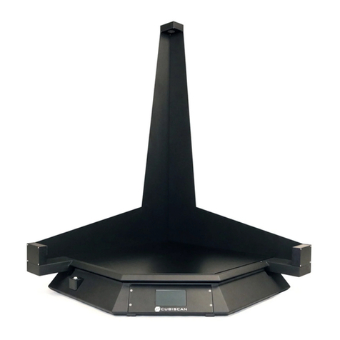
The CubiScan 125 is a static cubing system that uses a combination of
sensing technologies to measure and weigh irregularly-shaped parts and
components as well as boxed items. Small parts and items are measured
with great precision using infrared sensing technology, while larger boxed
items are measured with ultrasonic sensors.
The CubiScan 125 is commonly used to improve storage-space planning, for
carton size selection, repacking, check-weighing, and shipment manifesting
in medical, pharmaceutical, apparel, hardware, and consumer goods
distribution. It has an integrated touchscreen display and outputs to a
user-supplied PC. Capacity for the ultrasound sensors is 24 x 30 x 36 inches
with a resolution of 0.1 inches; gate sensors can measure up to 18 x 18 x 12
inches with a resolution of 0.05 inches. The CubiScan 125 also includes an
integrated, high-accuracy 50 x 0.005 lbs. scale.
Each unit has one active serial communication port, one Ethernet port, and
one USB port. Proprietary interface software, called Qbit™, is available and
allows for menu-driven operator control, data storage/transfer, and
diagnostics. A mobile cart and useful accessories such as a portable power
supply are available to create a completely mobile cubing, weighing, and
identification workstation.
The CubiScan 125 combines powerful sensing technologies to create a
flexible and economical solution for today’s most demanding cubing and
weighing applications.

Product Description Specifications
CubiScan 125 2
Specifications
Power Requirements
100 – 240 VAC, 50 – 60 Hz
Environmental
Operating Temperature: 32° to 104° F (0° to 40° C)
Humidity: 0 to 90% non-condensing
Measuring Sensor
Infrared light beam and ultrasonic
Figure 1
CubiScan 125

Product Description Specifications
CubiScan 125 3
Weight Sensor
Three load cells
Measuring Capacities
Weight Capacity: 0.005 to 50.000 lb (0.002 to 25.000 kg)
Weight Increment: 0.005 lb (0.002 kg)
Physical
Length: 44 in (112 cm)
Width: 44 in (112 cm)
Height: 51 in (130 cm)
Weight: 130 lbs (60 kg)
User Interface
Minimum PC Specifications:
Windows 10/8.1/8/7/XP/95/98/NT/2000, Pentium II processor, 20
megabytes of disk space, screen resolution setting of 800 X 600
Quantronix’s QBIT™ software can be used to interface with the CubiScan
125.
Measurement Range: Ultrasound
Sensors Gate Sensors
Length: 2.0 to 24.0 in
(5.0 to 60.0 cm)
0.10 to 18.00 in
(0.2 to 45.0 cm)
Width: 2.0 to 30.0 in
(5.0 to 80.0 cm)
0.10 to 18.00 in
(0.2 to 45.0 cm)
Height: 2.0 to 36.0 in
(5.0 to 90.0 cm)
0.10 to 12.00 in
(0.2 to 30.0 cm)
Measurement
Increment: 0.2 in (0.5 cm) 0.05 in (0.1 cm)
Measurement Time: < 3 seconds < 5 seconds
Object Colors: All colors Opaque

Product Description Specifications
CubiScan 125 4
Display:
Integrated TFT LCD touchscreen displays length, width, height, weight,
unit of measure, 2D and height profile, and diagnostic codes.
Outputs:
Serial (1), Ethernet (1), USB (1)

CubiScan 125 5
Chapter 2
Setup
This chapter provides instructions for assembling and setting up the
CubiScan 125. Perform the steps to set up the CubiScan 125 in the following
order:
•Unpacking (page 5)
•Placement (page 6)
•Assembly (page 7)
•Attaching top sensor support (page 8)
•Routing height sensor cable (page 9)
•Removing the shipping material (page 12)
•Placing the glass platform (page 13)
•Connecting power (page 14)
•Turning the CubiScan 125 on (page 14)
•Connecting to a computer or network (optional) (page 15)
•Installing the Qbit software (optional) (page 21)
Unpacking
The CubiScan 125 is shipped in a single container with all components. The
glass platform is packed in a separate cardboard box inside the crate.
Remove the wood slats and the packing material, and lift the CubiScan 125
components carefully from the crate. Do not remove the green foam
shipping supports between the scale base and platform or the wire tie that
holds the measuring gate in place; they will help prevent damage to the
load cells and gate while you are assembling the CubiScan 125.

Setup Placement
CubiScan 125 6
Examine the container and the CubiScan 125 carefully for any damage. If,
after unpacking, you discover any damage to the CubiScan 125, contact the
carrier immediately.
Carefully remove the CubiScan 125 and its components from the crate, and
place the CubiScan 125 on a solid, stable surface for assembly (see
“Assembling the CubiScan 125” on page 7.
If any of the components or accessories are missing or defective, contact
Quantronix.
Placement
The CubiScan 125 is designed to be operated in a warehouse environment;
however, for proper operation the following conditions should be met if
possible.
•Do not subject the CubiScan 125 to extremes in temperature or
humidity. Locate the CubiScan 125 as far from open freight doors as
Figure 2
CubiScan 125 in Crate

Setup Assembling the CubiScan 125
CubiScan 125 7
possible. Heaters or air conditioners should not blow directly on the
CubiScan 125.
•Avoid placing the CubiScan 125 in direct sunlight, as it may affect
measurement readings.
•Protect the CubiScan 125 from static electricity, especially the
touchscreen.
•Place the CubiScan 125 on a flat, sturdy surface as free from vibration as
possible. Excess vibration can reduce the accuracy of the CubiScan 125
scale.
•The CubiScan 125's platform is free-floating—it is resting on four springs
(load cells). Maintain a minimum of one-inch clearance at the back and
sides of the CubiScan 125. Do not rest objects against or set objects on
the CubiScan 125 when not in use.
•If a computer is used, place it as close to the CubiScan 125 as possible.
The operator needs to use the keyboard or mouse on the computer while
cubing and weighing packages using the CubiScan 125.
•Orient the CubiScan 125 so the touchscreen faces the operator.
Assembling the CubiScan 125
The CubiScan 125 is almost completely assembled when shipped. You only
need to attach the top sensor support, route the height sensor cable,
remove the shipping material, and place the glass platform.
•Place the base assembly of the CubiScan 125 on a stable surface. Make
sure that the CubiScan 125 is level. Adjust the leveling feet located in
each corner if necessary. (An optional cart, custom-designed for the
CubiScan 125, is available from Quantronix.)
•Do not remove the foam shipping supports between the scale base and
platform or the wire tie that hold the measuring gate in place; they will
help prevent damage to the load cells and gate while you are assembling
the CubiScan 125.

Setup Assembling the CubiScan 125
CubiScan 125 8
Attaching the Top Sensor Support
1. Remove the four raised screws from the top of the CubiScan 125 base
assembly, and retain them to attach the top sensor support.
2. Set the top sensor support in position on top of the CubiScan 125 gate
support, and line up the screw holes.
Figure 3
Raised Screws at Top of Assembled CubiScan 125
Remove four raised screws.

Setup Assembling the CubiScan 125
CubiScan 125 9
3. Insert the screws you removed in step 1 through the holes and tighten
them.
Attaching the Height Sensor Cable
The height sensor cable (gray cable with an RJ-12 connector) is connected
to the controller on the front of the base assembly and is routed and tied
through the base and gate support. It is coiled at the top of the gate support
for routing up the top sensor support.
Figure 4
Top Sensor Support Attached
Figure 5
Location of Height Sensor Cable

Setup Assembling the CubiScan 125
CubiScan 125 10
1. Route the height sensor cable from the top of the gate support up the
side of the top sensor support as shown below.
2. Place the supplied cable ties over the sensor cable and through the holes
on either side and secure them to hold the sensor cable in place.
Figure 6
Routing the Height Sensor Cable
Other manuals for 125
1
Table of contents
Other CubiScan Measuring Instrument manuals