Cuppone Pizzaform Operating manual

1
Cuppone Pizzaform
User and Installation Manual
Note: Pizza Equipment Professionals has provided this
manual as an English only copy of the Cuppone F. LLI SRL
Manual provided by the manufacturer. Words and
Descriptions may have been altered. If you have questions
please reference the Manufacturer’s Manual you have
received with your purchase.
www.PizzaEquipmentPros.com 800.655.1831 17981 S. Ideal Parkway. Manteca, CA. 95336. U.S.A. info@PizzaEquipmentPros.com

2
INDEX
Introduction
Initial Instructions
Explanation of Symbols
Risk Analysis
Technical Data (Pizzaform 30, 35)
Technical Data (Pizzaform 40, 45, 50)
General Specifications
Installation Requirements
Safety Distances
Instructions for the Installer
Uploading & Transport
Preparations and Checks
Positioning
Electrical Connections
Power Supply, Activation, Operation Verification
Pre-test
Control Panel Description
Instructions for the User
Turning On
Setting the Plate Temperature
Setting the Plate Contact Time (Dwell Setting)
Use
Shutting OFF
Countdown Function
Strike Counting Function
Troubleshooting
Recommendations Governing Use
Maintenance Instructions
Maintenance
Positioning of Main Controls
Wiring Diagram
Warranty Conditions
Limits
Exclusions

3
INTRODUCTION
The present manual refers to various electronic control PIZZAFORM pizza hot forming machine models.
The present manual was originally written in Italian. All other languages are translations.
Congratulations on selecting a product that was designed and constructed with advanced technology.
We recommend that you read through this manual fully before using this equipment. It contains very
important information and instructions regarding installation, use and maintenance.
The equipment you have purchased was carefully designed and constructed and has been subjected to strict
inspection tests in our laboratories, therefore we can guarantee its absolute safety and functionality.
Installation must be done according to the instructions by professionally qualified personnel who are able to
take on the responsibility for the installation and guarantee the best conditions for operation and safety.
TECHNICAL SUPPORT
The manufacturer is able to solve any technical problem concerning use and maintenance. In the remote
possibility of poor operation or a repair, only use qualified personnel or contact our authorized service
centers.
INITIAL INSTRUCTIONS
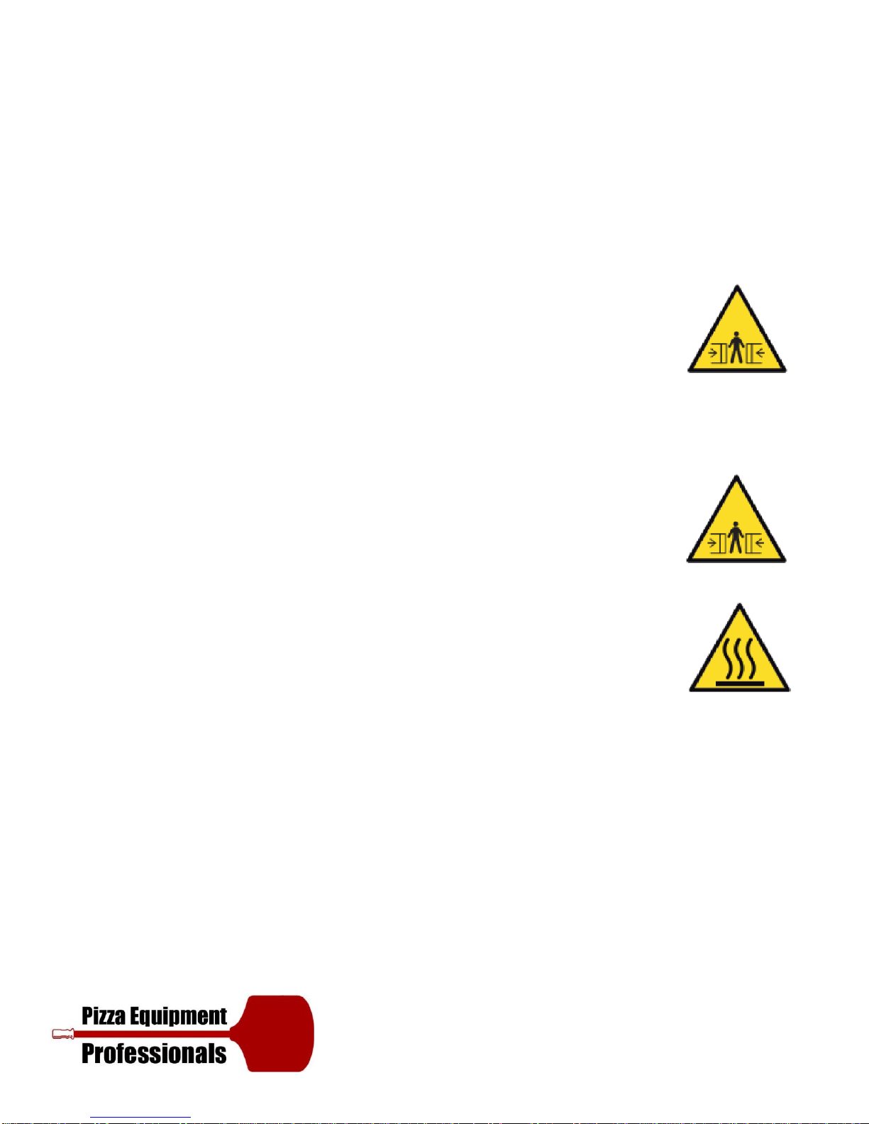
ATTENTION! Failure to comply with what is described in this handbook could jeopardize safety.
The manual must be kept carefully in an accessible location, it must also always accompany the product
during its life.
Before installing and using the equipment, this manual must be read carefully and the instructions it contains
must be followed scrupulously.
The manufacturer declines all civil and criminal liability for damage to people, property or animals deriving
from the failure to observe current safety regulations, failure to respect the contents of this manual and
from any printing or transcription errors.
It also declares that it reserves the right to make any changes to the product that it considers appropriate
without the obligation to provide notice.
Before handling, installing, or using the product, verify the suitability of the room where it will be located.
Make sure that all safety measures have been taken in order to avoid any accidents.

4
EXPLANATION OF SYMBOLS
Risk of Crushing Fingers
Equipotential
Risk of Electric
Shock
Risk of Blistering
Surface
Warning: Before using
the equipment
carefully read the
enclosed booklet.
Warning Gear
Wheels
Warning: In case of
arrest of the plate,
switch off and turn on
the machine. Do not
force it.

5
RISK ANALYSIS
The machine was designed in compliance with the Machinery Directive 2006/42/EC and Legislative Decree
no. 17 of the 27 January 2010.
In compliance with these standards an assessment of the possible damage resulting from risks to health and
the safety of operators of the machines in question, should a hazed come to light, was carried out.
According to the analysis there are outstanding risks associated with the use of the machine which cannot be
eliminated without loss of machine functionality and without increased cost.
These outstanding risks include:
The operators head may get crushed by the plates upon opening. The outstanding
risk is signaled by the pictogram on the machine.
Risk of breakage and projection of objects during insertion of the blade into the
protections during closure. Do not insert any objects into the protection grille when the machine is
moving, not even to unblock the plates.
In the case where the machine is blocked, switch it off and then on again.
Risk of crushing fingers at the plate piston base. The piston base is flared to enable
sliding of the fingers and to prevent catching; an outstanding risk of crushing of the
fingers where forced into position, remains.
Do not attempt to access or intervene at the piston base where the machine is moving.
The outstanding risk is signaled by the pictogram on the machine.
Risk of burns when touching the plates: during use, the surfaces of plates become hot,
we recommend taking extra caution. The outstanding risk is signaled by this pictogram.

6
Ensure that you keep a distance of at least 500 mm
(20
inches) between the equipment and other
equipment of inflammable materials.
We advise that you leave an unrestricted space of
at least 500 mm to the right side to allow for easy
access to the electrical system.
Leave the space above the equipment free: do not
place anything on it.
L: width P: depth H: height
Front View
Side View
Packaging
Dimensions
These cables can only be used provided
that their length does not exceed 2 m
between the point where the cable or
relative protection enters the equipment
and the plug input.
Plain View
Rear View

7
Front View
Side View
Packaging
Dimensions
Ensure that you keep a distance of at least 500 mm
(20
inches) between the equipment and other
equipment of inflammable materials.
We advise that you leave an unrestricted space of
at least 500 mm to the right side to allow for easy
access to the electrical system.
Leave the space above the equipment free: do not
place anything on it.
L: width P: depth H: height
These cables can only be used provided
that their length does not exceed 2 m
between the point where the cable or
relative protection enters the equipment
and the plug input.
Plain View
Rear View

8
GENERAL SPECIFICATIONS
1Iron supporting frame with thickness of 20 mm.
2Stainless steel body
3Self-braking motor (direct-current brake) with built-in thermal protection.
4Thick chromed plates with flared perimeter.
5Electronic control of temperature and plate contact time.
6EC certified safety devices.
7Lever to adjust the distance between plates.
8Protection grille.
To access the specifications explicit to your model, consult the technical data table above.

9
INSTALLATION REQUIREMENTS
Before starting the installation, check the following conditions that are necessary for proper equipment
operation and maintenance:
1) Handling: Make sure that the floor is able to support the weight of the equipment. Handle the packaged
equipment using a forklift or a pallet truck.
2) Electrical connection: Provide a box for the connection to the mains power supply in the immediate
surroundings.
3) Safety distances: It is mandatory that the minimum safety distances between the equipment and the
other equipment or inflammable material are respected (see page 20).
It is also prohibited to use the equipment in areas at risk of explosion. The indicated distances must be
increased in the presence of heat sensitive material.
SAFETY DISTANCES
It is mandatory that the minimum safety distances between the equipment and the other equipment or
inflammable material are respected (see page 20).
It is also prohibited to use the equipment in areas at risk of explosion. The indicated distances must be
increased in the presence of heat sensitive material.
Leave this area
unobstructed

10
INSTRUCTIONS FOR THE INSTALLER
The gas, water, electrical systems and the rooms where the equipment will be installed must comply with
the safety, accident prevention and fire prevention standards applicable in the country of use; otherwise
the Manufacturer shall not be liable for any direct or indirect damage to people or property.
ATTENTION! Always shut off the main electric switch when installing, servicing or repairing the equipment.
Before making the electrical connection, make sure that the voltage and frequency stated on the
specifications plate corresponds to those of the power supply.
A circuit breaker with auto-protection and sufficient capacity must be installed upstream of the equipment; it
must have a contact opening distance that permits complete disconnection. (the specifications regarding the
opening distance of the contacts and the maximum leakage current must be taken from current regulations).
The equipment must be earth bonded.
The equipment must also be connected to an equipotential system using the screw located at the back of the
equipment, to the lower left, marked with the symbol
This equipotential system must comply with current standards.
Install the equipment in a well ventilated area, as incorrect air recirculation impedes optimal operation and
the “wellbeing” of the people working near the equipment. Do not obstruct the ventilation system in the
area where the equipment is installed.
Do not obstruct the ventilation and exhaust holes in this or any other equipment. At the end of installation,
dispose of the packaging pursuant to local ecological and environmental regulations.
The material used for packaging is compatible with the environment and can be kept safely or burnt in a
specific waste combustion system. The plastic components subject to disposal with recycling are marked
with this symbol

11
UNLOADING AND TRANSPORT
PREPARATIONS AND CHECKS
Unwrap the equipment and carefully remove the protective film.
In the instance where glue residue remains on surfaces, remove then using soapy water; do not use corrosive
products.
ATTENTION! Check that all equipment parts are in good condition and that there are no defects or
breakages; in such an instance, contact the manufacturer who will advise you on the procedure to follow.

12
POSITIONING
The machine must be positioned on the appropriate support supplied by the company, which must be
manufactured to satisfy the characteristics.
In the case where it is placed above a different base, ensure that it is level and is able to support the weight
(see the technical specifications table on pg.14).
Carry out this operation with the support of suitable lifting mechanisms, using the ringbolt provided, which
should be screwed to the top of the machine after having removed the protective cap. Ensure that you
keep a distance of at least 500 mm (20 inches) between the equipment and other equipment or
flammable materials.

13
ELECTRICAL CONNECTIONS
Only qualified personnel must carry out electrical connection.
The technical data plate, located on the back of the equipment, contains all the necessary information for
correct connection.
The equipment must be connected to a power supply with a H05 RN-F type cable (supplied by the installer).
To carry out this operation, remove the right side equipment panel, connect the cable to the terminal board
and secure it with the relative cable gland located on the back of the equipment itself.
Earth the equipment and connect it to the circuit; the terminal intended for this very purpose can be found
on the back of the equipment, and is marked with the internationally-recognized symbol.
Connect the cable to the automatic master switch (omnipolar differential magnothermal
switch with a contact opening of at least 3 mm), arranged in the immediate vicinity.
The manufacturer will not assume any responsibility in the instance where the above described is not
respected.

14
OPERATION VERIFICATION
Start up the equipment using the instructions provided below.
Check the correct operation of all electrical components, whilst explaining how to best use the equipment
and how to carry out routine maintenance and cleaning operations to the user.
POWER SUPPLY ACTIVATION

15
PRE-TEST
Prior to delivery to the customer, the equipment is
tested at the manufacturer’s workshops both with
regard to functionality as well as to safety.
When the unit is turned on for the first time is
recommended that the temperature is set at 150°C and
left on for at least 1 hour.
During this phase, the equipment will produce fumes
and unpleasant odors due to the evaporation of the
moisture contained in the insulation.
These fumes and odors will disappear during the
subsequent operating cycles.
It is recommended that during the first operating cycle,
a thin layer of olive oil is placed on the hot plates using
paper and is subsequently cleaned using absorbent
paper, to then take a dough ball, flatten it and then
reshape it into a ball, repeating this until the dough no
longer sticks to the plates.
This operation serves to establish a protective layer over
the plates which facilitates movement of the pasta
during flattening; this must be repeated every time that
thorough cleaning of the plates is carried out.
ATTENTION: Please refer to the user’s manual for
startup and programming.

16

17
INSTRUCTIONS FOR THE USER
This equipment was designed exclusively for flattening dough balls to make pizza or similar food products
as per the methods indicated in this booklet.
Any use other than what is indicated is considered improper, potentially dangerous for people and animals
and could cause irreparable damage to the equipment. Improper equipment will void the warranty;
furthermore, the manufacturer does not consider itself liable for damage to people, animals or property.
FIRE HAZARD Leave the area around the equipment free and clean of combustibles. Do not keep
flammable material near this equipment.
All of the models described in this handbook have parts that are heated by direct contact, by air convection
or fumes and radiation: attention - risk of burns! Do not handle parts without suitable protection.
ATTENTION: It is prohibited to place flammable solids or liquids, such as spirits, on the plates during
operation. Supervise the equipment when in operation and do not leave food on the plates unsupervised!
ATTENTION: Always turn off the main electrical switch when no longer using the equipment, especially
during cleaning operations or a prolonged period of inactivity.
If you notice any anomaly (ex. damaged power cable, etc...), poor operation or failure, do not use the
equipment and contact a service center authorized by the manufacturer.
Original spare parts must be used under penalty of cancellation of the warranty. Place the emergency
telephone numbers in a visible location.
This equipment is not suitable for use by people (including children) with reduced physical, sensorial or
mental capacity or those lacking experience and knowledge, unless a person who is responsible for their
safety supervises them or provides them with instruction regarding equipment use.
Personnel using the equipment must be professionally prepared and periodically trained in its use and in
safety and accident prevention regulations. Children must be supervised to make sure they do not play with
the equipment or its parts.

18
TURNING ON
Unblock the machine by turning the STOP key (12) clockwise. Switch the
machine on by pressing the ON/OFF key (11). After a few sec the display
(1) will present the top plate temperature and the display (3) the
bottom plate temperature.
SETTING THE PLATE TEMPERATURE
To set the top plate temperature, press either key (5) or (6); the display (1)
will begin to flash; press key (5) or (6) up until the desired temperature has
been achieved. To set the bottom plate temperature, press either key (7) or
(8); the display (3) will begin to flash; press key (7) or (8) up until the desired
temperature has been achieved.
N.B. The temperature which has been set at the time the machine is
switched off, will be automatically saved and proposed once again when the
machine is switched on again.
SETTING THE PLATE CONTACT TIME (Dwell Setting)
To set the plate contact time, press key (10); the display (1) will begin to flash
and the set time will be displayed; press keys (5) and (6) up until the desired
time has been achieved.

19
USE
Wait until the plates have reached the set temperature; attempt
to flatten a few balls by varying the plate distance using the lever
(13) up until the desired depth has been achieved.
Flattening is achieved by positioning the dough ball at the
center of the bottom plate and keeping the protection grille
(14) lowered.
Once the bottom plate has returned to the original position,
the protection grille can be raised and the dough disk can be
removed taking care not to burn yourself on the plate surface.
Find the setting most suited to the type of dough used; the
machine is ready to begin operating.
SHUTTING OFF
To switch the machine off simply press the ON/OFF key (11).
ATTENTION: The protective grille must only be raised when
the lower plate has finished the levelling cycle and has
returned to the original position; should you wish to lower
the bottom plate beforehand to reduce the diameter of the
disk plate, raise the grille before the end of the cycle.

20
COUNTDOWN FUNCTION
The board is equipped with a countdown function which automatically
turns on the equipment.
To activate this function, press Timer key (10) with the equipment
turned off. The time remaining before the oven is due to turn itself on
will appear on display (1); to modify the time, use keys (5) and (6)
(maximum limit 99.5: 99 hours and 50 minutes). When making the
selection, the TIMER Led (9) flashes. Should you wish to exit the function
and cancel the countdown, press key (10) or key (11) to switch the
equipment on. Otherwise, the equipment will switch on upon expiry of
the set time, according to the time set at the time of switching off the
aforementioned.
WARNING! In the instance of power failure, the countdown value is
saved and will resume upon the return of power: for example, let’s
consider the following situation, if 4 hours were remaining before the
oven was due to turn itself on and the power supply was cut o for 30
minutes, once the power supply has returned, 4 hours will still remain
before the oven is due to turn itself on.
Other manuals for Pizzaform
2
Table of contents