Current Tools 281 User manual

Current Tools™Model 281 Bending Table
for use with Model #254 Hydraulic Conduit Bender
CURRENT TOOLS • P. O. BOX 17026 GREENVILLE, SC 29606
800.230.5421 or 864.721.4230 • FAX 864.721.4232
www.currenttools.com
Assembly, Operating, Safety
and Parts Manual
3/2019
This manual is free of charge. All personnel who assemble, operate or service
this equipment should have a copy of this manual and read and understand its
contents. To request a copy, call or write to the address below.
Read and understand this material before assembling, operating
or servicing the 281 Bending Table and 254 Hydraulic Bender.
Failure to understand how to safely assemble and operate this
equpment may result in serious injury or death.

2
TABLE OF CONTENTS — 281 BENDING TABLE
Safety Alerts ................................................................................ 2-4
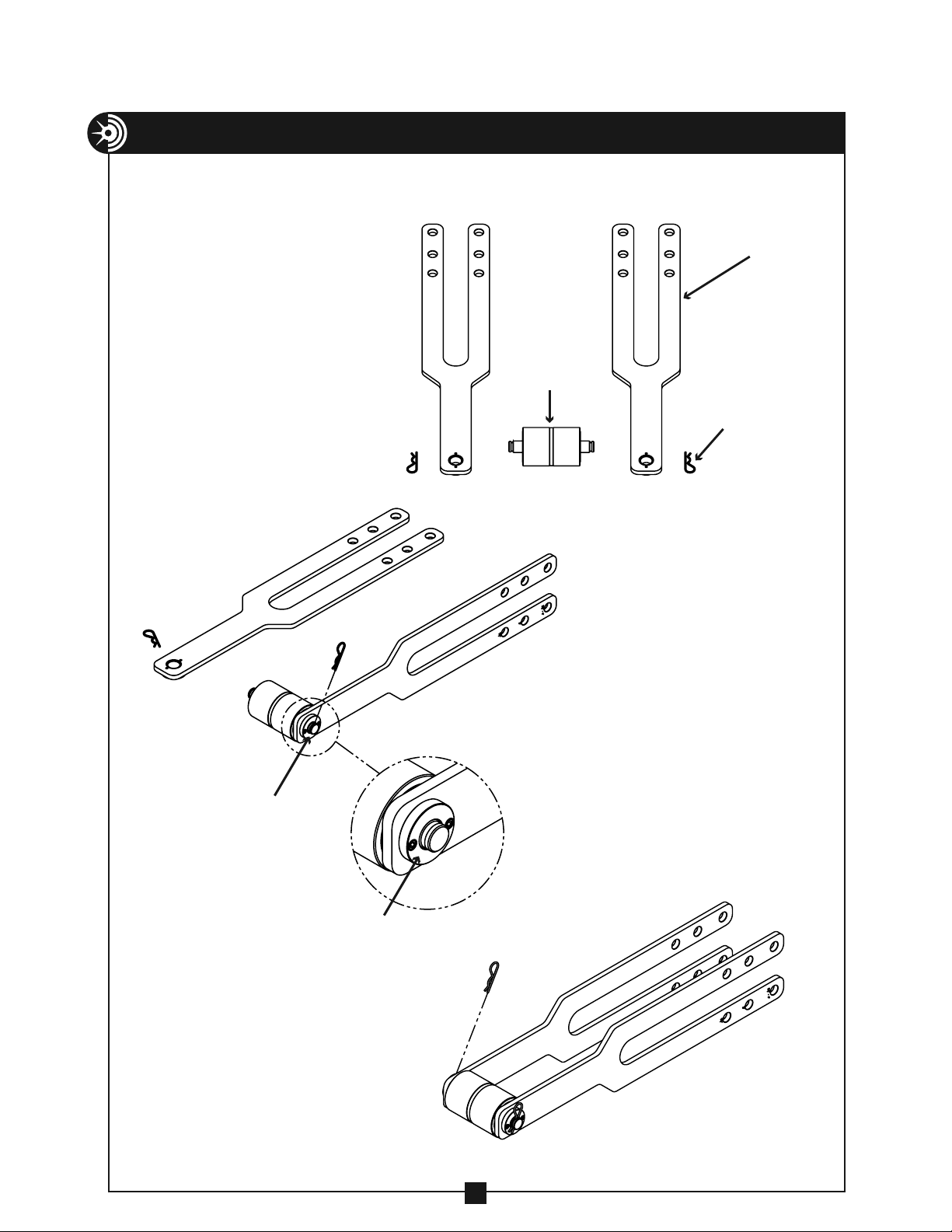
Components – 281 Bending Table .................................................4
Major Components & Parts List – 254 Bender .............................5
Assembly Instructions ................................................................ 6-9
Bender Assembly & Mounting Instructions ......................... 10-26
Exploded Views & Parts List.................................................. 27-28
RETAIN SAFETY INFORMATION
This manual should be read and understood by all personnel who assemble,
operate or service this bending table and hydraulic bender. Failure to
understand how to safely assemble and operate these units could result
in injury or death. This bending table and hydraulic bender should only be
assembled, operated and serviced by qualified personnel.
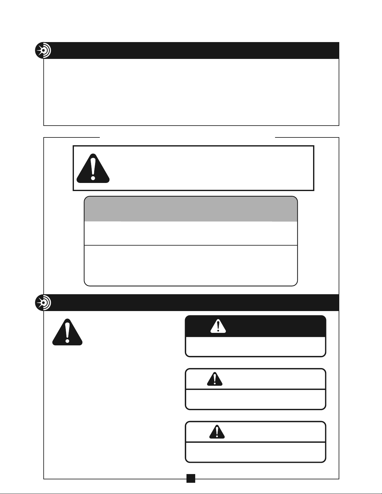
SAFETY ALERTS
Hazards or unsafe practices which, if not avoided,
COULD result in serious personal injury or death.
WARNING
Hazards or unsafe practices which, if not avoided,
COULD result in minor personal injury or property damage.
CAUTION
Immediate hazards which, if not avoided, WILL result in
serious personal injury or death.
DANGER
THIS SAFETY SYMBOL is used to call your attention to instructions
that concern your personal safety. It means: ATTENTION! BE AWARE!
THIS IS AN IMPORTANT SAFETY INSTRUCTION!
Read, understand, and follow these safety instructions. Failure to follow
these safety instructions may result in injury or death.
Safety Alert
Symbol
Hazards or unsafe practices which, if not avoided,
COULD result in serious personal injury or death.
WARNING
Hazards or unsafe practices which, if not avoided,
COULD result in minor personal injury or property damage.
CAUTION
Immediate hazards which, if not avoided, WILL result in
serious personal injury or death.
DANGER
THIS SAFETY SYMBOL is used to call your attention to instructions
t
hat concern your personal safety. It means: ATTENTION! BE AWARE!
THIS IS AN IMPORTANT SAFETY INSTRUCTION!
Read, understand, and follow these safety instructions. Failure to follow
t
hese safety instructions may result in injury or death.
Safety Alert
Symbol
THIS SAFETY SYMBOL is used to call your
attention to instructions that concern your
personal safety. It means: ATTENTION! BE
AWARE! THIS IS AN IMPORTANT SAFETY
INSTRUCTION!
Read, understand and follow these safety
instructions. Failure to follow these safety
instructions my result in injury or death.
* Greenlee®and CamTrack®are registered
trademarks of Emerson Electric Co. , which has no
affiliation with Current Tools.
Refer to the Current Tools Model #254 Assembly, Operating and Maintenance,
Safety and Parts Manual for complete bending instructions, charts, etc.
When using the 281 Bending Table with Greenlee®881 or 881 CamTrack®*
Bender, read and understand the bender manufacturer’s operating and safety
instructions before attaching to or operating with the 281 Bending Table.
Failure to do so may result in serious injury or death.
IMPORTANT

NEVER operate the bender in an explosive atmosphere.
NEVER operate the bender in wet or damp locations.
DO NOT expose the bender to rain.
ALWAYS disconnect the bender from the hydraulic pump before
servicing and when not in use.
ALWAYS inspect the bender before operating. Replace any
damaged, missing or worn parts. Check for alignment of moving
parts, binding of moving parts, breakage of parts and any other
conditions that may affect its operation.
NEVER alter this equipment. Doing so will void the warranty.
ALWAYS keep hands and feet away from pinch points such as
bending shoes, follow bars, saddles, conduit and other moving parts.
ALWAYS use appropriate bending shoe, follow bar and saddle for
the size conduit to be bent.
NEVER allow the carriage with vise to contact any component of
the bender or bending table during a bend.
ALWAYS keep conduit under control when unloading.
ALWAYS keep the path of the bending conduit clear of
obstructions. Make sure all obstacles are clear of the bending
path BEFORE you bend the conduit.
ALWAYS wear approved safety glasses when the bender is
in operation.
ALWAYS wear proper apparel. Do not wear loose clothing, gloves,
neckties, rings, bracelets, or other jewelry which may
get caught in moving parts. Non-slip footwear is recommended.
Wear protective hair covering to contain long hair.
NEVER stand in direct line with the hydraulic cylinder while
operating or servicing the bender. Some parts of the cylinder
are under high pressure and can be propelled with considerable
force.
NEVER stand in direct line with the follow bar while operating the
bender. The follow bar is under high pressure during use and can
be propelled with considerable force.
ALWAYS read and understand the safety and operating instructions
supplied with your hydraulic pump.
ALWAYS keep children away. All visitors should remain a safe
distance from work area.
3
3
IMPORTANT SAFETY INFORMATION
WARNING
DANGER
CAUTION
WARNING
DANGER
CAUTION
WARNING
DANGER
CAUTION
WARNING
DANGER
CAUTION
WARNING
DANGER
CAUTION
WARNING
DANGER
CAUTION
WARNING
DANGER
CAUTION
WARNING
DANGER
CAUTION
WARNING
DANGER
CAUTION
WARNING
DANGER
CAUTION
WARNING
DANGER
CAUTION
WARNING
DANGER
CAUTION
WARNING
DANGER
CAUTION
WARNING
DANGER
CAUTION
WARNING
DANGER
CAUTION
WARNING
DANGER
CAUTION

4
IMPORTANT SAFETY INFORMATION — continued
WARNING
DANGER
CAUTION
The bender and some accessories exceed 50 lbs. and will
require more than one person to lift, transport and assemble.
Only use the bender for its intended purpose as specified
in this manual.
ALWAYS maintain bender with care. Keep bender clean for
best and safest performance.
CHECK all hose connections prior to use and ensure they are
properly connected. Improper connections may not allow the
hydraulic cylinder to operate.
WARNING
DANGER
CAUTION
WARNING
DANGER
CAUTION
WARNING
DANGER
CAUTION
COMPONENTS – 281 BENDING TABLE
MAJOR COMPONENTS – BENDER
4
9
5
2
3
10
1
6
7
8
For use with Model #254 Hydraulic Conduit Bender. Can also be used with
Greenlee®Model #881 or #881 CamTrack®Benders*.
NOTE: 2 each 10' lengths of 2" rigid
conduit used as the table supports
are to be supplied by the user.
* Greenlee®and CamTrack®are registered trademarks of Emerson
Electric Co., which has no affiliation with Current Tools.
KEY NO. DESCRIPTION QTY
1281-221 Carriage with vise 1
2281-400 Bender mounting unit 1
3281-3 Ram positioning unit 1
4280-5 Leg support 2
5280-6 Legs 4
6280-7 Magnetic protractor 1
7281-4 Pump mounting
brackets
4
8281-5 Conduit clamps 4
9281-6 Pump mounting track 2
10 281-CPLNGASSY 90˚Coupling
assembly
1
104 Storage Box
(not shown)
1

5
MAJOR COMPONENTS – BENDER
ITEM CATALOG DESCRIPTION QTY.
1 254-100 HYDRAULIC CYLINDER (INCLUDES ITEM #2) 1
2 254-102 CYLINDER MOUNTING BLOCK 1
3 254-107 CLEVIS PIN 1
4 254-148 CYLINDER BLOCK PIN 2
5 254-006 SPRING CLIP 6
6 254-104 FRAME SIDE ASSEMBLY 2
7 254-151 ROLLER ASSEMBLY 1
8 254-103 CLEVIS 1
9 254-108 CLEVIS RETAINING CLIP 1
10 254-149 SADDLE PIN 1
11 105 STORAGE BOX 1
12 506 CASTER SET – 2 RIGID, 2 SWIVEL 1
13 291 HYDRAULIC HOSE 1
MAJOR COMPONENTS – PARTS LIST
7
5
4
3
1
2
9
8
10
6
13
11
12
* Greenlee®and CamTrack®are registered trademarks of Emerson Electric Co.
For complete shoe, follow bar and
saddle listing, refer to Model #254
operating manual.
All major components will fit Greenlee®
Model #881 CamTrack®Bender*

6
ASSEMBLY INSTRUCTIONS
MAJOR COMPONENTS – BENDER
Insert two of the legs into the leg support
as shown in Figure 1 and tighten the
bolts to hold the legs in place. Repeat for
second leg support.
Insert the ends of the two 10' pieces of 2"
rigid conduit (supplied by the user) into
one leg support assembly and tighten the
two bolts on each side. See Figure 1.
TIGHTEN AFTER
INSERTING 2” RIGID CONDUIT
(2 BOLTS EACH SIDE)
2” RIGID CONDUIT – 10 FT LONG
(SUPPLIED BY USER)
TIGHTEN TO
SECURE LEGS
(ONE FOR EACH LEG)
LE
G
LEG SUPPORT
Next, slide the carriage with vise
onto the conduit as shown in Figure
2. The chain side of the vise should
face away from the one leg support
assembly you have completed.
Now slide the bender mounting unit onto the
two 10' lengths of rigid conduit. Be sure that the
follow bar guide “ears” point away from the
carriage with vise. See Figure 3.
CARRIAGE WITH VISE
LEG SUPPORT
BENDER MOUNTING UNIT
FOLLOW BAR
GUIDE EARS
FIGURE 1
FIGURE 2
FIGURE 3

7
ASSEMBLY INSTRUCTIONS — continued
MAJOR COMPONENTS – BENDER
Insert the two 10' lengths of conduit into the remaining leg support assembly and
tighten the four bolts against the conduit. See Figure 4.
Place the bender mounting unit 15 inches away from the leg support you have just
completed and tighten the 2 bolts on the bottom of the bender mounting unit against
the two 10' lengths of rigid conduit to keep the bender mounting unit in place. See
Figure 4.
Next, attach the two pump
mounting tracks to the
bending table with the 4
conduit clamps as shown
in Figure 5. DO NOT tighten
these firmly at this time.
NOTE: Be sure the table is
level before continuing.
FIGURE 4
FIGURE 5
REMAINING
LEG SUPPORT
ASSEMBLY
TIGHTEN THESE BOLTS
(ONE EACH SIDE)
TIGHTEN 2 BOLTS
EACH SIDE
15"
DO NOT TIGHTEN THESE
CLAMPS FIRMLY YET
PUMP
MOUNTING TRACKS
5"

8
SET-UP
MAJOR COMPONENTS – BENDER
FIGURE 6
281 BENDING TABLE
– Ready to mount pump and bender

9
PUMP MOUNTING BRACKET OPTIONS
ASSEMBLY INSTRUCTIONS — continued
Attach the pump mounting brackets to the 4 corner holes of the pump. See
drawings below for pump mounting bracket installation. Place the pump with
brackets attached onto the pump mounting track. Secure the pump mounting
brackets in place by tightening the bolts on the bottom of each pump mounting
bracket. Next, firmly tighten the conduit clamps.
PUMP BA
SE
2
3
24
1
8
PUMP BA
SE
2
3
25
1
8
22
BLIND HOLE STYLE BRACKET THROUGH HOLE STYLE BRACKET
CONDUIT CLAMPS
PUMP MOUNTING
TRACK
See below for
pump mounting
bracket options
NOTE: When using the Current Tools
Model #292 pump, read and understand the
operating and safety manual supplied with it.

10
BENDER ASSEMBLY AND MOUNTING INSTRUCTIONS
CONDUIT CENTERLINE BENDING RADII
1. Locate the two frame
sides, roller assembly
and two spring clips.
2. Place one frame side onto the
roller assembly as shown and
secure with a spring clip.
NOTE: The collar in the end of
the frame side must be facing
outward.
ROLLER
ASSEMBLY
FRAME SIDE
SPRING CLIP
COLLAR
COLLAR
3. Place the second frame side
onto the roller assembly and
secure with a spring clip.
NOTE: The collar in the end
of the frame side must be
facing outward.

11
BENDER ASSEMBLY AND MOUNTING INSTRUCTIONS — continued
4. Insert the completed frame assembly with
roller into the bender mounting unit as shown.
FRAME SIDE COLLAR
BENDER MOUNTING UNIT
FRAME
ASSEMBLY
FRAME
ASSEMBLY
BENDER
MOUNTING
UNIT
FOLLOW BAR
FRAME SIDE
START
5. Select the follow bar for the size
conduit you will be bending.
Insert the follow bar between
the frame sides with the end
marked “START” as shown.
NOTE: For illustration purposes,
the 4" shoe, follow bar and saddle
have been selected.

12
BENDER ASSEMBLY AND MOUNTING INSTRUCTIONS — continued
FOLLOW BAR
CARRIAGE
WITH VISE
6. Use the carriage with vise to
support the back side of the
follow bar as shown.
7. Insert the ram positioner between
the frame sides as shown.

13
BENDER ASSEMBLY AND MOUNTING INSTRUCTIONS — continued
RAM
POSITIONER
CLEVIS
9. Place the hydraulic cylinder, with clevis
attached, onto the follow bar. Attach
one end of the hydraulic hose to the
90° coupling assembly on the hydraulic
cylinder. Attach the other end of the
hose to the coupling on the hydraulic
pump.
NOTE: Adjust the clevis so that the
holes of the clevis line up with the holes
of the ram positioner as shown.
8. Place the clevis onto the end of the
hydraulic cylinder and secure with the
clevis retaining clip as shown.
CLEVIS
RETAINING
CLIP
CLEVIS
NOTE: Insert and
secure the 90°
coupling assembly
into the coupler body
on the top of the
hydraulic cylinder.
COUPLER BOD
Y
90° COUPLING
ASSEMBLY

14
BENDER ASSEMBLY AND MOUNTING INSTRUCTIONS — continued
10. Rotate the pump valve lever
clockwise to the closed position
and advance the hydraulic cylinder
approximately 14" towards the ram
positioner. DO NOT OVER EXTEND.
Align the clevis holes with the ram
positioner holes and insert the clevis
pin. Secure the clevis pin with a
spring clip.
CLEVIS PIN
SPRING CLIP
CLEVIS
11. Fully insert one cylinder block pin through both frame
sides in the holes marked for bending 3" conduit. The
pin should be inserted in the frame side holes that are
farthest away from the hydraulic cylinder as shown.
Secure the pin with a spring clip.
CYLINDER
BLOCK PIN
FRAME SIDE

15
BENDER ASSEMBLY AND MOUNTING INSTRUCTIONS — continued
12. Rotate the hydraulic cylinder into
position above the frame sides.
SPRING
CLIP
CYLINDER
BLOCK PIN
CYLINDER
BLOCK PINS
CYLINDER
BLOCK
SPRING CLIP
13. Slowly rotate the pump valve lever counter-
clockwise to the open position and retract the
hydraulic cylinder until it is secured in the frame
sides. Rotate the pump valve lever clockwise to the
closed position to stop the cylinder before it contacts
the cylinder block pin. Remove the cylinder block pin
from the 3" conduit bending hole in the frame sides
(See Figure 15A).
Next, Advance or retract the cylinder until the holes in the
cylinder block line up with the holes in the frame sides that
correspond to the size conduit you are bending. Insert both
cylinder block pins through the frame sides and cylinder
block. Secure both pins with spring clips. (See Figure 15B).
SPRING
CLIP
CYLINDER
BLOCK PIN
CYLINDER
BLOCK PINS
CYLINDER
BLOCK
SPRING CLIP
FIGURE 15A
FIGURE 15B

16
BENDER ASSEMBLY AND MOUNTING INSTRUCTIONS — continued
14. Rotate the pump valve lever
counter-clockwise to the open
position and fully retract the
hydraulic cylinder. Pull the
spring clip and remove the
clevis pin from the clevis and
ram positioner. Remove the ram
positioner. Rotate the clevis 90° to
the position shown in Figure 16.
SADDLE
PIN HOLE
15. Place the correct size bending shoe
between the frame sides, making sure
the saddle pin hole is located as shown.
FIGURE 16
FRAME SIDE
CLEVIS
(IN POSITION TO
INSE
RT BENDING SHOE)

17
BENDER ASSEMBLY AND MOUNTING INSTRUCTIONS — continued
16. Rotate the pump valve lever clockwise to the
closed position and advance the cylinder until the
clevis holes are aligned with the correct conduit
type (Rigid/IMC or EMT) hole in the bending shoe.
Insert the clevis pin and secure with a spring clip.
17. Rotate the pump valve lever
counter-clockwise to the
open position to retract the
hydraulic cylinder and raise
the shoe.
CLEVIS PIN
CLEVIS
SPRING CLIP
BENDING SHOE
RIGID/IMC
EM
T
NOTE: Arrows on the bending
shoe indicate the correct hole for
bending either Rigid/IMC or EMT
conduit.

18
BENDER ASSEMBLY AND MOUNTING INSTRUCTIONS — continued
19. Place the conduit between the shoe and follow bar,
resting the conduit on the carriage with vise. Rotate the
pump valve lever clockwise to the closed position and
activate the pump until the shoe almost makes contact
with the conduit.
CONDUIT
CARRIAGE WITH VISE
CARRIAGE
WITH VISE
18. Slide the carriage with vise from
underneath the follow bar and position
it at the far end of the bending table.

VISE CHAIN CONDUIT
CARRIAGE
WITH VISE
20. Locate the carriage with vise near
the far end of the conduit, making
sure that it will not make contact with
the pump mounting track prior to
completing the bend. Place the vise
chain around the conduit and tighten
to secure.
CONDUIT
FOLLOW BAR
“START”
BENDER
MOUNTING
UNIT
21. Push the end of the follow bar marked
“START” towards the bender mounting unit
until the “ear” of the follow bar touches the
bender mounting unit (See illustration at left).
Place the correct saddle and saddle pin within
reach for assembly to the bending shoe.
19
BENDER ASSEMBLY AND MOUNTING INSTRUCTIONS — continued
BENDER
MOUNTING UNIT
FOLLOW BAR
“EAR”
“START”

20
BENDER ASSEMBLY AND MOUNTING INSTRUCTIONS — continued
22. While rocking the bender frame, push
the bottom of the bending shoe to the
position shown for attaching the saddle
and saddle pin.
PUSH
SPRING CLIP
SADDLE
SADDLE PIN
SADDLE
INSERT LIP
23. While holding the shoe against the
conduit, place the saddle under the
conduit with the saddle insert lip
facing away from the follow bar.
Slide the saddle towards the shoe
and align the saddle holes with the
shoe hole. Insert the saddle pin
through both the saddle and shoe
and secure it with a spring clip.
Table of contents
Popular Industrial Equipment manuals by other brands

Innotech
Innotech INNOTECH BEF 401-10 Instructions for installation and use

Vertiv
Vertiv Liebert MicroPOD 230V Installer/user guide

Thermo Scientific
Thermo Scientific CTS Xenon installation guide

Siemens
Siemens 1MB115 Installation and maintenance manual

ABB
ABB HT846276 Operation manual

Grunbeck
Grunbeck GENO-WT-K 42 Operation manual

SMC Networks
SMC Networks EX510 Series manual

APPLIED MATERIALS
APPLIED MATERIALS CoolEND 0190-13674 Installation, operation, basic service

ERICO
ERICO CADDY CPNAM Series instruction sheet

Siemens
Siemens 3VL9400-3HF0 Series operating instructions

DIGITIZE
DIGITIZE DET-6C Installation and operation manual

National Flooring Equipment
National Flooring Equipment Trolley-10 OPERATING & SERVICE MANUAL