Current Tools 282 User manual

Current Tools™Model 282 Transfer Cart
for 2½" to 4" hydraulic bender shoes, follow bars and saddles
CURRENT TOOLS • P. O. BOX 17026 GREENVILLE, SC 29606
800.230.5421 or 864.721.4230 • FAX 864.721.4232
www.currenttools.com
Assembly, Operating, Safety
and Parts Manual
01/2022
This manual is free of charge. All personnel who assemble, operate or service this equipment should have a copy of this manual
and read and understand its contents. To request a copy, call or write to the address below. All information, specifications and
product designs may change due to design improvements or updates and are subject to change without notice. Current Tools
does not assume any liability for damages resulting from misuse or incorrect application of its products.
Read and understand this material before assembling,
operating or servicing the 282 Transfer Cart. Failure to
understand how to safely assemble and operate this
equpment may result in serious injury or death.
Patent Pending

2
TABLE OF CONTENTS — 282 TRANSFER CART
Safety Alerts .................................................................................................2
Important Safety Information .....................................................................3
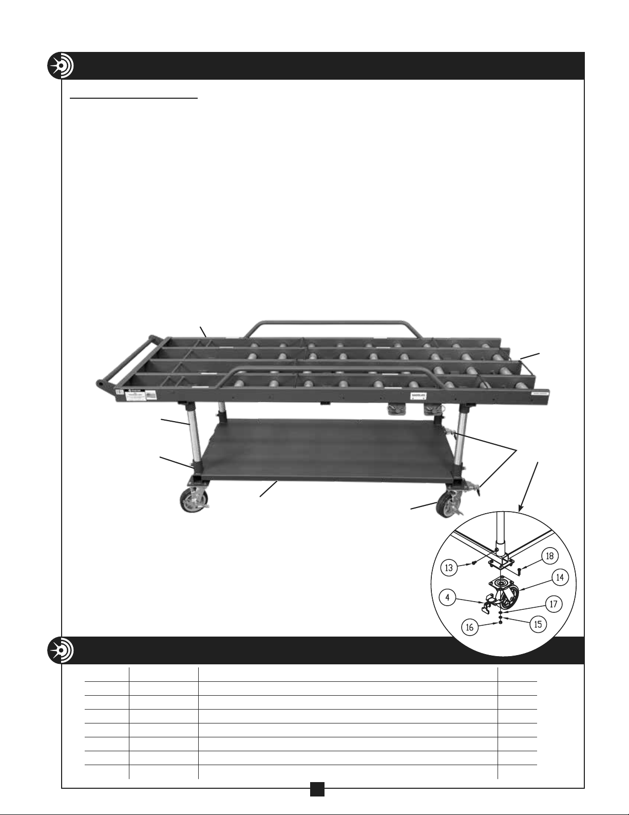
Specifications and Features ........................................................................4
Assembly and Operating Instructions ..................................................5-11
Exploded View and Parts List ...................................................................12
RETAIN SAFETY INFORMATION
This manual should be read and understood by all personnel who
assemble, operate or service this Transfer Cart. Failure to understand
how to safely assemble and operate this unit could result in injury
or death. This Transfer Cart and hydraulic bender should only be
assembled, operated and serviced by qualified personnel.
SAFETY ALERTS
Hazards or unsafe practices which, if not avoided,
COULD result in serious personal injury or death.
WARNING
Hazards or unsafe practices which, if not avoided,
COULD result in minor personal injury or property damage.
CAUTION
Immediate hazards which, if not avoided, WILL result in
serious personal injury or death.
DANGER
THIS SAFETY SYMBOL is used to call your attention to instructions
that concern your personal safety. It means: ATTENTION! BE AWARE!
THIS IS AN IMPORTANT SAFETY INSTRUCTION!
Read, understand, and follow these safety instructions. Failure to follow
these safety instructions may result in injury or death.
Safety Alert
Symbol
Hazards or unsafe practices which, if not avoided,
COULD result in serious personal injury or death.
WARNING
Hazards or unsafe practices which, if not avoided,
COULD result in minor personal injury or property damage.
CAUTION
Immediate hazards which, if not avoided, WILL result in
serious personal injury or death.
DANGER
THIS SAFETY SYMBOL is used to call your attention to instructions
t
hat concern your personal safety. It means: ATTENTION! BE AWARE!
THIS IS AN IMPORTANT SAFETY INSTRUCTION!
Read, understand, and follow these safety instructions. Failure to follow
t
hese safety instructions may result in injury or death.
Safety Alert
Symbol
THIS SAFETY SYMBOL is used to call your
attention to instructions that concern your
personal safety. It means: ATTENTION! BE
AWARE! THIS IS AN IMPORTANT SAFETY
INSTRUCTION!
Read, understand and follow these safety
instructions. Failure to follow these safety
instructions my result in injury or death.

ALWAYS inspect the cart before operating. Replace any
damaged, missing or worn parts. Check for alignment of moving parts,
binding of moving parts, breakage of parts and any other conditions that
may affect its operation.
DO NOT lift cart while loaded.
ONLY lift the cart from underneath the cart base, NEVER lift the cart by the
roller bed.
ALWAYS unload the cart prior to transporting.
NEVER alter this equipment. Doing so will void the warranty.
ALWAYS use appropriate bending shoe, follow bar and saddle for
the size conduit to be bent.
ALWAYS keep shoe group components under control when rolling or using
the transfer cart.
ALWAYS keep the gates closed on all rows when rolling the cart and when
the rows are not in use.
ONLY roll on a firm, flat, smooth surface.
ALWAYS keep the path of the shoe group components clear of
obstructions.
ALWAYS load or unload the bender components onto or off of their
designated locations on the cart.
Some hydraulic bender components exceed 50 lbs. and will require more
than one person to lift, transport and assemble.
Only use the transfer cart for its intended purpose as specified
in this manual.
ALWAYS keep hands and feet away from pinch points.
ALWAYS wear approved safety glasses.
ALWAYS wear proper apparel. Do not wear loose clothing, neckties, rings,
bracelets, or other jewelry which may get caught in moving parts. Non-slip
footwear is recommended. Wear protective hair covering to contain long
hair.
ALWAYS keep children away. All visitors should remain a safe
distance from work area.
NEVER sit, ride or stand on the transfer cart.
ONLY use with shoe group components from the Current Tools Model #254
Hydraulic Bender OR Greenlee®Model #881 CamTrack®Hydraulic Bender*
Greenlee®and CamTrack®are registered trademarks of Greenlee Tools Inc., which has no affiliation
with Current Tools.
3
3
IMPORTANT SAFETY INFORMATION
WARNING
DANGER
CAUTION
WARNING
DANGER
CAUTION
WARNING
DANGER
CAUTION
WARNING
DANGER
CAUTION
WARNING
DANGER
CAUTION
WARNING
DANGER
CAUTION
WARNING
DANGER
CAUTION
WARNING
DANGER
CAUTION
WARNING
DANGER
CAUTION
WARNING
DANGER
CAUTION
WARNING
DANGER
CAUTION
WARNING
DANGER
CAUTION
WARNING
DANGER
CAUTION
WARNING
DANGER
CAUTION
WARNING
DANGER
CAUTION
WARNING
DANGER
CAUTION
WARNING
DANGER
CAUTION
WARNING
DANGER
CAUTION
WARNING
DANGER
CAUTION

4
FEATURES
• Easy mobility of 21⁄2" thru 4" shoe groups (shoes, follow bars, saddles)
• Reduced lifting of heavy components lessens fatigue and chance of injury
• Extra storage tray on the bottom of the cart base
• Ability to adjust cart height
• Component locations clearly marked for easy identification
• For use with Current Tools Model #254 Hydraulic Bender shoe group
components (shoe, follow bar, saddle). Greenlee®Model #881 CamTrack®
shoe group components will fit the Transfer Cart as well.
• Standard legs provide correct height for use with Current Tools Model #281
Bending Table or Greenlee®Model #1813 Bending Table
Greenlee®and CamTrack®are registered trademarks of Greenlee Tools Inc., which has no affiliation
with Current Tools.
SPECIFICATIONS
model no. — 282
width — 31¾"
length — 87"
height — 36"
weight — 320 lbs. – cart only
maximum weight cap. — Roller Bed — 650 lbs.
Lower Shelf — 150 lbs.
shoe group cap. — 21⁄2" shoe, follow bar, saddle
3" shoe, follow bar, saddle
31⁄2" shoe, follow bar, saddle
4" shoe, follow bar, saddle

5
ASSEMBLY AND OPERATING INSTRUCTIONS
ASSEMBLING CART
1. Using the hardware provided, attach the casters to the caster plates on the four corners of
the cart base. (See Figure 5).
NOTE: ONLY three of item #s 15 thru 18 are used per caster
NOTE: There are two swivel locks (Item #4) provided and should be installed on the casters
on the front of the cart. (See diagram below).
2. Insert the four legs into the receiver tubes at the four corners of the cart base. (See Figure 5).
NOTE: To adjust the height of the cart, the user can substitute the legs with four pieces of 1 1/4"
rigid conduit cut to the desired length. All legs must be the same length.
3. With a helper, lift the roller bed and place it on top of the four legs installed in Step 2.
Ensure that the legs are fully inserted into the four receiver tubes on the bottom of the
roller bed. (See Figure 5).
4. Install the bolts (8 total of item #13) into the receiver tube threaded nuts and tighten
against the legs. (See Figure 5).
Figure 5
PARTS LIST – CASTERS AND HARDWARE
ITEM # PART # DESCRIPTION QTY.
4 282-001 SWIVEL LOCK 2
13 503-32 BOLT – HEX HEAD CAP GR5 ZINC (3/8-16 ×5/8) 8
14 513-001 CASTER 4
15 452-27 3/8 LOCK WASHER 12
16 452-28 3/8 HEX NUT 12
17 506-3 WASHER – FLAT 3/8 (USS) ZINC 12
18 281-2D BOLT – HEX HEAD CAP GR5 ZINC (3/8-16 × 1.25) 12
Front of
Cart
Legs
Receiver Tube
with Threaded
Nuts (8 Total)
Casters
(All 4 Corners)
Swivel
Locks
Cart Base
Roller Bed

5. The gates on the roller bed are installed
at the factory. Ensure that all eight gates
(two per row) are in place and operable.
To open, lift the gate from the spring side
and rotate towards the front of the cart.
To secure, return the gate to the retainer
hole. (See Figure 6).
LOADING CART
NOTE: Engage the brake on all casters before loading or removing components
1. A set of pins (two per sides) are mounted under the roller bed to store the four saddles. Pull the
spring clips out of the mounting holes and slide the saddles onto the pins with the “u” of the
saddle under the roller bed. Replace the spring clips to secure the saddles. (See Figure 6A).
6
ASSEMBLY AND OPERATING INSTRUCTIONS — CONTINUED
Figure 6A
Figure 6
Gate
Spring
Side
Gate
Retainer
Hole

7
ASSEMBLY AND OPERATING INSTRUCTIONS — CONTINUED
Figure 7A
WARNING
DANGER
CAUTION
3½"
Inner Row
4"
Inner Row
3" Row
2½" Row
Follow Bar
“Ears” “START” Saddle
Mounting
Hole
Shoe Stop
Handle
(Rear of Cart)
Front
of Cart
Front GateFront Gate
Rear GateRear Gate
Figure 7
Handle
(Rear of Cart)
2. Decals indicate correct placement for all
components. To load the shoes and follow
bars onto the cart, start with the 3 ½" and
4" inner rows of the cart. (See Figure 7).
3. Open the front and rear gates for the row you will be loading. Place the shoe in the correct
row of the roller bed with the saddle mounting hole facing the rear of the cart and slide
the shoe until it touches the shoe stop. NOTE: To sit in the correct position, the shoe must
touch the shoe stop. (See Figure 7A). Return the rear gate in front of the shoe to its closed
position. Next, place the corresponding follow bar on the roller bed with the “ears” of the
follow bar facing upward and the end of the follow bar marked “START” facing the shoe.
Roll the follow bar towards the bending shoe until it reaches the rear gate. Return the front
gate to its closed position. Repeat this process for the remaining shoes and follow bars.
ALWAYS keep the gates closed on all rows when rolling the cart.

8
ASSEMBLY AND OPERATING INSTRUCTIONS — CONTINUED
OPERATING CART
1. Release the brakes on all the casters and roll the cart to your bender.
2. Line up the row with the follow bar and shoe you will be using with the Current Tools Model
#254 Hydraulic Bender mounted on the #281 Bending Table. (See Figure 8).
3. Engage the brake on all casters.
Model #282
Transfer Cart
Model #281
Bending Table
Figure 8

9
ASSEMBLY AND OPERATING INSTRUCTIONS — CONTINUED
OPERATING CART — continued
4. Load your follow bar, shoe and saddle by following the steps outlined below.
NOTE: For illustration purposes, only the 4" shoe and follow bar are being shown.
A. Open the gate on the front of the cart and slide the follow bar between the frame sides on the
bender, leaving approximately half of the follow bar on the transfer cart as shown in Figure 9A.
B. Open the gate in front of the bending shoe and slide the shoe toward the
follow bar as shown in Figure 9B.
Figure 9A
Figure 9B

10
ASSEMBLY AND OPERATING INSTRUCTIONS — CONTINUED
OPERATING CART — continued
C. Align the shoe and follow bar as
shown in Figure 10A.
D. Rotate the shoe onto the follow bar
as shown in Figure 10B.
E. Slide the shoe along the follow bar
until the clevis mounting holes are
located underneath the clevis as
shown in Figure 10C.
NOTE: Consult your bender
operating manual for clevis
mounting instructions.
Figure 10A
Figure 8B
Figure 10B
Figure 10C

11
ASSEMBLY AND OPERATING INSTRUCTIONS — CONTINUED
OPERATING CART — continued
F. Advance the hydraulic cylinder
and align the clevis with the
correct hole on the shoe for the
type conduit you will be bending
(Rigid/IMC or EMT). Insert the
clevis pin and secure with a spring
clip. Retract the hydraulic cylinder
and raise the shoe.
See Figure 11A.
G. Slide the follow bar to the start
position. See Figure 11B.
H. Disengage the caster brakes and roll the cart away from the bender.
NOTE: Swivel locks are provided on the front casters to help with maneuvering the cart.
I. Refer to your hydraulic bender manual to complete the set up for bending conduit.
J. After bending is complete, reverse this procedure to return the shoe and follow bar to the
Transfer Cart.
Figure 11A
Figure 11B

12
EXPLODED VIEW
PARTS LIST
ITEM # PART # DESCRIPTION QTY.
188-2 PIN – COTTER (1/8 ×1/2) 8
2100-011 SPRING — GATE 8
3254-006 SPRING CLIP 4
4282-001 SWIVEL LOCK 2
5282-002 CONVEYOR ROLLER — 7 9/16" LONG 18
6282-003 CONVEYOR ROLLER — 8 9/16" LONG 18
7282-106 ROLLER BED 1
8282-116 GATE, OUTER 4
9282-117 GATE, INNER 4
10 282-120 BASE — CART 1
11 282-123 LEG, STANDARD 4
12 412-12 WASHER — FLAT SAE ZINC (5/16) 16
13 503-32 BOLT – HEX HEAD CAP GR5 ZINC (3/8-16 ×5/8) 8
14 513-001 CASTER 4
15 452-27 3/8 LOCK WASHER 12
16 452-28 3/8 HEX NUT 12
17 506-3 WASHER – FLAT 3/8 (USS) ZINC 12
18 281-2D BOLT – HEX HEAD CAP GR5 ZINC (3/8-16 ×1.25) 12
Table of contents
Other Current Tools Outdoor Cart manuals
Popular Outdoor Cart manuals by other brands

Gude
Gude GGW 500 Translation of the original instructions

LDI Spaces
LDI Spaces SAFCO 4199 Assembly instructions

Black cat
Black cat MH1100-1 owner's manual

Seville Classics
Seville Classics WEB483 manual

U-Line
U-Line H-2529 quick start guide

MedViron
MedViron Height Adjustable Medical Carts Operation & maintenance manual

Cornwell Tools
Cornwell Tools Pro CTBMM500CAR Assembly instructions

MetalTech
MetalTech WALL HAULER 3600 Series OPERATIONAL SAFETY AND ASSEMBLY INSTRUCTIONS

SCHUNK
SCHUNK VERO-S RWA2 Assembly and operating manual

Fimco
Fimco TC-10P-EC-B owner's manual

VYPER
VYPER ROBUST STEEL SPORT Assembly guide

Hoss
Hoss 42814 installation instructions