Current E-WAND Guide

1
Installation Manual and
User Guide

2 3
Installation Manual
And
User Guide
Please carefully and fully read the following Installation
Manual and User Guide. Without proper installation and
programming, your E-Wand will not perform as designed.
Please save these instructions.
Please be aware that the E-Wand may behave dierently
based on blind manufacturer, slat size, and tilt mechanism
location.
For assistance, please contact our customer service
department at 844-307-7435, or see our additional support
materials at www.currentproductscorp.com/support.
Instructional Videos can be viewed by going to
www.currentproductscorp.com/support
or by scanning the QR Code with your smart
phone.
TABLE OF CONTENTS
4
5
6
6
7
7
8
11
13
13
13
17
17
19
19
20
20
21
22
22
22
23
23
24
25
26
28
30
32
37
To register your E-Wands, visit
www.currentproductscorp.com/products-registration. If you
prefer to register via phone, call 844-307-7435. If you prefer
to mail in a registration, please go to page 37.
4 5
PACKAGE CONTENTS
AND PARTS IDENTIFIER
Installation Manual
and
User Guide
14
3
25
CH
14
3
25
CH
14
3
25
14
3
25
HORIZONTAL BLIND
MOUNT B
VERTICAL BLIND
MOUNT C
(6) AA 1.5V ALKALINE
BATTERIES D
VERTICAL BLIND
REINFORCEMENT TAPE E
EXTRA ADHESIVE STRIPS F
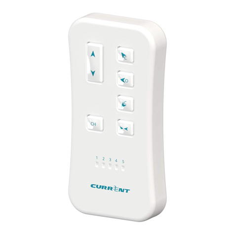
OPTIONAL REMOTE
Wall MOUNT J
OPTIONAL REMOTE I
INSTALLATION MANUAL AND
USER GUIDE H
HORIZONTAL TILT
Converter G
Optional EXTENSION
HANDLE K
A
Wand Hook
Sleeve L
MEET YOUR
E-Wand
Attachment Hook a
Programming Button b
Retaining Sleeve c
Light Sensor Switch d
Temperature Sensor
Switch
Control Housing h
Twist Handle f
Battery Cap g
The E-Wand allows the user to motorize the slat movement for both
,or with the
optional remote control, the user can fully control the position of an individual blind’s
Additionally, your E-Wand contains both light and temperature sensors to
privacy at night and can be set to open and close the slats to assist with maintaining a
Lastly, the E-Wand
(provided) which are easy to replace and will provide, in most cases, over a year between
e

6 7
HORIZONTAL BLINDS
HEADER
MANUAL TWIST
WAND
OR CORDED TILT
LIFTING CORD
SLATS
NOTE: Some blinds use a corded tilt mechanism to tilt the slats instead of a wand. If
your horizontal blinds have a corded tilt mechanism, you will need to convert it to a
wand tilt mechanism using the horizontal tilt gear. Instructions for converting to a
wand tilt mechanism can be found on page 26.
TILT GEAR
STEM VALANCE
Vertical BLINDS
SLATS
HEADER
MANUAL TWIST WAND
NOTE: The E-Wand is not compatible with vertical blinds that
use a rope or chain to open and close the slats.
TILT GEAR
STEM
SLAT
ATTACHMENT
ASSEMBLY AND MOUNTING THE
E-Wand
For further assistance during the assembly and mounting process, please view our online
POWER UP
Figure 1.1; Unscrew Battery Cap
Figure 1.2; Insert Batteries
To install the batteries, unscrew the
BATTERY CAP g located at the bottom
Remove Battery Cap
Insert the batteries one after the other
inserted, screw the BATTERY CAP g
tune.
Install Batteries

8 9
Detach Original Tilt Wand and Attach the E-Wand
Figure 2.1; Slide Hook Sleeve onto Stem
If your blind has an open hook for the
original tilt mechanism as opposed to a
closed eyelet, slide the plastic SECURITY
SLEEVE L over the tilt hook to cover the
E-Wand A ATTACHMENT HOOK to
by connecting or inserting the slat
ATTACHMENT HOOK a to your blind’s
SENSOR SWITCHES & are in front
Figure 2.2; Hook
Wand onto Tilt Stem
Figure 2.3; Push up
Retaining Sleeve
Test Fit the Blind Mount
BLIND MOUNT B by snapping the
mount up or down along the CONTROL
HOUSING h until your blind’s tilt gear
stem and the E-Wand ATTACHMENT
HOOK a can be seen through the cutout
of the horizontal blind mount is resting
Figure 3.1; Snap on
Blind Mount
Figure 3.2; Proper
Positioning
Verify that the blind mount can rest
the blind slats resting in the fully open
Figure 3.3; Tilt Stem
Protrudes from
Headrail Preventing
a Flush Mount
Figure 3.4; Blind
Slats Touch
E-Wand
HORIZONTAL BLINDS INSTALLATION GUIDE
Before installing the E-Wand, make sure you are able to freely tilt your
blinds in both directions by turning the twist wand that originally came
If your blinds utilize a cord to tilt the slats,
Installation Manual and User Guide [Pg. 26].
Make sure the blind slats are in the horizontal or fully opened position
and the header is free of dirt, grime, and grease. If not, use a household
cleaner to clean the header before installation.
Attach the E-Wand
d e
a

10 11
VERTICAL BLINDS INSTALLATION GUIDE
Make sure the blind slats are uniformly opened in the tilted fully opened
position, then remove the original manual tilt wand.
Before installing the E-Wand, make sure you are able to freely tilt your blinds
in both directions by turning the twist wand that originally came with your
The E-Wand is not compatible with vertical blinds that use
a rope or chain to tilt the slats.
Remove Twist Wand
Install the Vertical Blind Mount
Install the VERTICAL BLIND MOUNT C
on the E-Wand by sliding the clear plastic
bellows over the ATTACHMENT HOOK a
sensor switches will be facing the inside
Figure 6.1; Install Blind Mount
extends beyond the top or the side of the
blind’s header, use scissors to trim the
BLIND MOUNT B is even with or slightly
MOUNT B , verify the header is clean
and dry and that the tube of the blind
mount is snapped into place on the
E-Wand, then remove the backing on the
Figure 4.2; (Optional) Trim Blind Mount
to Fit
Secure Blind Mount
Figure 5.1; Remove Backing from
Adhesive Strip to Attach it to Header
You have now completed installing your E-Wand. You may now proceed
to Programming the E-Wand [Pg. 13].
Attach the E-Wand to the Vertical Blind
Pull down on the VERTICAL BLIND
MOUNT’S C bellows to expose the
the E-Wand ATTACHMENT HOOK a onto
Figure 7.1; Hook on E-Wand
The blind mount must have a secure
supplied EXTRA ADHESIVE STRIPS F to
your blind’s header to build the mounting
Figure 4.1; (Optional) Build out Header
Make Any Necessary Adjustments

12 13
Use the included VERTICAL BLIND
REINFORCEMENT TAPE E to reinforce
Carefully replace the slat back onto the
slat attachment hook by reversing the
the slat is oriented the same as the other
Figure 8.2; Reinforce Vertical Slat
Figure 8.3; Reattach Vertical Slat
You have now completed installing your E-Wand. You may now proceed
to Programming the E-Wand [Pg. 13].
PROGRAMMING THE
E-Wand
For further assistance during the programming process, please view our
During programming, be conscious that there are several series of beeps that
the number of beeps you have heard, for example, a SINGLE BEEP (1) and
E-Wand Programming Beeps
Pairing the Remote and Grouping E-Wands
Programming the Slat Positions
Setting the Favorite Position
Setting the Preferred Closed Position
Master Reset
Realign the E-Wand
Single Beep (1)
Sextuple Beep (6)
Figure 8.1; Detach First Slat
Recommended: Reinforce First Slat
Remove the adjacent vertical slat by
carefully pushing the slat upward and
Figure 7.2; Proper Positioning
Release the blind mount to allow the
bellows to extend upwards toward the
Be sure the slat attachment can move
through the open slot in the blind mount
PROGRAMMING SLAT POSITIONS
When programming the E-Wand, you will be listening for audible beeps to
We recommend you minimize the noise within the room while programming
During the programming phase, if an error is made, the E-Wand will play
E-Wand.
Figure 9.1; Programming Beeps

14 15
Place the E-Wand into Slat Position Programming Mode
To place the E-Wand into the Slat Position
Programming Mode, press and hold the
PROGRAMMING BUTTON b until you
Note: Prior to hearing a DOUBLE BEEP
The E-Wand is now in Slat Position
Figure 10.1; Press and Hold
Programming Button
Set the First Position- Full Closed (Down for Horizontal
Blinds or Left for Vertical Blinds)
Twist the E-Wand TWIST HANDLE f
to the FULL DOWN OR LEFT position,
over tightening can cause damage to
the blind.
Figure 11.1;
Twist Blinds to
Full Closed
Figure 11.2;
Push and Hold
Programming
Button
Press and hold the PROGRAMMING
BUTTON b until you hear a SINGLE
Set the Third Position- Full Closed (Up for Horizontal Blinds
or Right for Vertical Blinds)
Twist the E-Wand TWIST HANDLE f
so the slats reach the FULL UP OR RIGHT
the slats.
Press and hold the PROGRAMMING
Figure 13.1;
Twist Blinds to
Full Open
Figure 13.2;
Push and Hold
Programming
Button
Set the Second Position- Full Open
Twist the E-Wand TWIST HANDLE f
the slats to the FULL OPEN position, then
Note: During twisting, if you move past
the full open position, do not twist
the opposite way back to full open.
Instead, restart programming. To get
out of programming mode, power cycle
the unit by partially unscrewing and
successfully power cycled when you hear
Figure 12.1;
Twist Blinds to
Full Open
Figure 12.2;
Push and Hold
Programming
Button
Press and hold the PROGRAMMING

16 17
Set the Final Position- Full Open
Twist the E-Wand TWIST HANDLE f
to move the slats back to the FULL
PROGRAMMING BUTTON b until the
The slats will automatically move DOWN
OR LEFT and back to the FULL OPEN
position to verify that the positions
have been set properly and that you
have completed programming the slat
position, do not twist the opposite way back to full open. Instead, restart
programming. To get out of programming mode, power cycle the unit by
Figure 14.1;
Twist Blinds to
Full Closed
Figure 14.2;
Push and Hold
Programming
Button
Create and manage A
TWIST GROUP
(OPTIONAL)
You may create a Twist Group prior to or after installation and
programming. We recommend linking E-Wands prior to installation on
challenging to reach windows.
A Twist Group allows you to group multiple E-Wands together so each will
respond to the manual twist movement given to any other E-Wand you have
Place the E-Wands you wish to group in Pairing Mode
On the E-Wands you wish to group
together, one by one, press and hold the
PROGRAMMING BUTTON b until you
hear a SINGLE BEEP (1), then release
Figure 15.1; Press and Hold
Programming Button
Establishing a Twist Group

18 19
created, each programmed E-Wand in the
in the group that have not had their slat
Figure 16.2; Jog
REMOVING An E-Wand FROM A TWIST GROUP
In some instances, you may want to remove an E-Wand from a previously
b on the E-Wand you
wish to remove from the group until you hear a SINGLE BEEP (1), then
Once more, b until you
Repeat this process to remove any additional desired E-Wands from the
ADDING An E-Wand TO A TWIST GROUP
In some instances, you may want to add an E-Wand to an existing Twist
b on the E-Wand you
originally designated as the master until you hear a SINGLE BEEP (1),
On any E-Wand you wish to add to the group, press and hold the
buntil you hear a SINGLE BEEP (1), then
After all additional E-Wands have been initialized, return to the master
b again until you hear
Choose and Assign the Master E-Wand
Once you have initiated the linking
sequence on EACH E-Wand, choose an
E-Wand that will be centrally located in
Press and hold THIS E-Wand's
PROGRAMMING BUTTON b again until
You have now completed linking your
Figure 16.1; Press and Hold
Programming Button

20 21
MAKING SENSE OF THE SENSORS
SENSOR SWITCH POSITIONS
Off
Light or Temperature
Fully Automatic
Light Sensor closes
the slats at sunset
and opens the slats at
Temperature sensor
opens the slats around
69 F and closes the
Semi-Automatic
Light sensor only
closes the slats at
Temperature sensor
only closes the slats
Temperature Sensor Switch
Light Sensor Switch
Pro-Tip: Based on the direction your window is facing, as well as other
environmental factors, different blinds may close or open at different times
opens and closes at your preferred time, then grouping all E-Wands together
Once the LIGHT SENSOR or TEMPERATURE SENSOR makes an automatic
The LIGHT SENSOR will prevent the TEMPERATURE SENSOR from opening
A manual movement of an E-Wand via the TWIST HANDLE f or REMOTE
When blinds are grouped, one sensor triggered movement will move all
SENSOR FEATURES

22 23
Other Procedures
Setting the Preferred closed position
When using the automated features, the E-Wand may close the blinds
closed position:
Twist the E-Wand TWIST HANDLE f until the slats reach your desired
b on the E-Wand until
Realign YOUR E-Wand
Based on the construction of your blinds, you may notice the full open position
this occurrence, you can simply realign your originally programmed E-Wand
Move the E-Wand manually by twisting the TWIST HANDLE f to the
b until you hear a
MASTER RESET YOUR E-Wand
All twist groups, paired remotes, and positional settings will be removed from
b until you hear a
After you hear the beeps,
bagain
Master reset mode can be escaped by waiting until the mode times out,
or by twisting the E-Wand TWIST HANDLE f after hearing the monotone
SETTING THE FAVORITE POSITION
(for the remote control)
The FAVORITE Button on the remote control allows the user to program a slat
position unique to the user which moves all slats included on that channel to
Twist the E-Wand TWIST HANDLE f until the desired position is
b on the E-Wand until
Your FAVORITE Button will now move that blind to the programmed favorite
After the E-Wand is set, test by moving your blinds, then pressing the

24 25
CHANGING BATTERIES
When the batteries are depleted, the E-Wand will play a tune instead of
Unscrew the Battery Cap
Using two hands, carefully and slowly
the battery tube, so be prepared to catch
Replace bad batteries with six (6) new
Insert batteries with the positive (+) end
Replace Batteries
Figure 17.1; Unscrew Battery Cap
Figure 18.1; Insert New Batteries
Screw Battery Cap Back On
ATTACHING An E-Wand Extension Handle
For blinds that are taller than average, it may be necessary to attach an
Carefully remove the BATTERY CAP g
Unscrew the Battery Cap
Screw on Extension Handle
Attach EXTENSION HANDLE K onto the
Reattach Battery Cap
Reattach BATTERY CAP g onto the end
Figure 19.1; Unscrew Battery Cap
Figure 20.1; Screw on Extension Handle

26 27
CONVERTING A HORIZONTAL
CORDED TILT BLIND
For further assistance with converting a corded tilt blind, please view our
You will need to remove your blinds from the window and perform the next
Remove the Existing Tilt Mechanism
Remove the existing corded tilt gear
Figure 21.1; Standard Assembly
Remove the tassels by either cutting the
cord or removing the knots at the end of
Figure 21.2; Remove Tassels
Typically, the tilt gear is removed by
sliding the rod out of the tilt gear, slightly
bending the header and lifting the tilt
Sometimes the rods are retained in place
through either a rod pin, crimps or the
installs these tilt gears differently, they
Figure 21.3; Standard Assembly
Install the Horizontal Tilt Converter
Determine the size and shape of the rod
Locate the ADAPTER from the selection
supplied which matches your rod shape
Place the gear’s stem through the
opening in the header and slide the rod
through the gear to its original position
brackets were removed while removing
the corded tilt gear, replace back into
Figure 22.1; Snap in Adapter
Figure 22.2; Slide Stem through Header
You have now converted your tilt mechanism. You may now proceed to
Installing the E-Wand [Pg. 8].

28 29
QUICK USER GUIDE
After the initial programming, simply twist the TWIST HANDLE f of the
ungrouped E-Wand to move your blind to the desired slat position and
Operation of a Single E-Wand
Once a group is created, you can twist any E-Wand in the group and release
Controlling a Group of Blinds
Operation of a Single E-Wand Within a Group
of Blinds
Once a group has been set, twisting any E-Wand TWIST HANDLE f will
momentarily push the PROGRAMMING BUTTON b without triggering a
beep, then twist the TWIST HANDLE f until the blinds reach the desired
E-Wand TWIST HANDLE f , and you will be released from the triggered
Light Sensor Automation
The E-Wand has an internal light sensor providing the capability to
automatically close your slats at night to provide full privacy in the room, and
The LIGHT SENSOR SWITCH d allows the user to control the light sensor
Middle: Sensor will open the slats around sunrise and close
Temperature Sensor Automation
The E-Wand contains an internal temperature sensor providing the capability
to automatically close your slats when the temperature near the window is
function is designed to help with energy savings and provide comfort in the
The TEMPERATURE SENSOR SWITCH e allows the user to control the
Middle: Sensor will open the slats around 69 F and

30 31
SAFETY INFORMATION
WARNING
CAUTION
CAUTION
FCC STATEMENT
two conditions:
Warning:
NOTE: This equipment has been tested and found to comply with the limits for a Class B
equipment generates, uses, and can radiate radio frequency energy and, if not installed
and used in accordance with the instructions, may cause harmful interference to radio
television reception, which can be determined by turning the equipment off and on, the
user is encouraged to try to correct the interference by one or more of the following
measures:
• Connect the equipment into an outlet on a circuit different from that to
RF WARNING STATEMENT
IC STATEMENT
this device must accept any interference, including interference that may cause undesired
Le présent appareil est conforme aux CNR d’Industrie Canada applicables aux appareils
tour brouillage radioélectrique subi, même si le brouillage est susceptible d’en comprom-
This equipment complies with the radiation exposure limits in an uncontrolled environ-
Cet équipment est conforme aux limites d'exposition aux radiations dans un environment

32 33
WARRANTY INFORMATION
LIMITED WARRANTY
E-Wand™ (the “Product”) is and will remain for a period of one (1) year from the date
of delivery to Customer as evidenced by Customer’s proof of purchase (the “Warranty
Period”), free of defects in materials and workmanship, provided that the Product used
for its intended purpose and is properly serviced in accordance with the User’s Manual
Period the Product fails to conform to the foregoing warranty by reason of defects in
materials or workmanship, Customer shall promptly notify Manufacturer in writing, and
Manufacturer at its option shall repair or replace the defective Product or component part
without charge to Customer, except for: (A) costs incurred in transporting the Products
or component parts to and from Manufacturer’s designated dealer or its manufacturing
plant; and (B) charges for labor or other costs incidental to the removal or remounting
of component parts repaired or replaced under this Warranty, both of which shall be
shall not extend or obligate Manufacturer to take any action with respect to: (i) Products
recommended by Manufacturer, including any Products in which parts not manufactured
or approved by Manufacturer have been installed; (ii) Products which have not been
regularly and properly serviced in accordance with the User’s Manual or which have
otherwise been neglected; and (iii) ordinary wear and tear, service and maintenance and
replacement items; (iv) the Product has been used, or attempted to be used, for other
than the customary usage or for other than the Product’s intended use; (v) the Product
has been subject to mishandling, misuse, or abuse; (vi) the product has suffered damage
other cause which the product was not designed to withstand; or (vii) damage to the
distributor, dealer, agent or representative is authorized to change the terms of this
Limited Warranty in any way, to extend the warranty time periods, or to grant additional
LIMITATION OF LIABILITY
EXCEPT AS SPECIFICALLY STATED IN THE PARAGRAPHS IMMEDIATELY ABOVE,
MANUFACTURER MAKES NO WARRANTY OR REPRESENTATION, EXPRESS OR IMPLIED,
INCLUDING, WITHOUT LIMITATION, ANY WARRANTY OF MERCHANTABILITY OR
THE OBLIGATIONS AND LIABILITIES OF MANUFACTURER THEREUNDER REPRESENT
CUSTOMER’S SOLE AND EXCLUSIVE REMEDIES AND ARE EXPRESSLY MADE IN LIEU OF
ANY AND ALL OTHER REMEDIES, WARRANTIES, GUARANTIES OR LIABILITIES, EXPRESS
ARE NO WARRANTIES WHICH EXTEND BEYOND THE DESCRIPTION ON THE FACE
PURCHASE PRICE FOR THE PRODUCTS, NOR SHALL MANUFACTURER BE LIABLE FOR
ANY SPECIAL, INDIRECT, INCIDENTAL OR CONSEQUENTIAL DAMAGES OF ANY NATURE
OTHER LEGAL RIGHTS

34 35
SERIAL NUMBERS
Serial NumberProduct Location
Notes:
Serial Number Location

36 37
Product Registration
Serial NumberProduct Type
Customer Information
(Name)
(Street Address)
(City) (State) (Zip) (Country)
(Email) (Phone Number)
Where did you buy your products?
Remove the page, then mail it to:
To register your products electronically, visit
(Name of Dealer or Online Merchant)
(e.g. “E-Wand” or “E-Wand Remote”)

38 39
Mail To:
Other manuals for E-WAND
4
Table of contents
Other Current Window Blind manuals
Popular Window Blind manuals by other brands

WAREMA
WAREMA Venetian 2.25/35.17 Operating and maintenance instructions

Inspire
Inspire MIAMI Assembly, Use, Maintenance Manual

DecorQuip
DecorQuip 191695 manual

SelectBlinds
SelectBlinds Deluxe Aluminum Blinds installation instructions

Creation Baumann
Creation Baumann PLITRIC PL 41 Assembly instruction

Velux
Velux VELUX INTEGRA Solar SSL installation instructions