Curtis Dyna-Fog MAXI-PRO 2D ULV Instruction Manual

1
MAXI-PRO™2D ULV
Multi-Purpose
Cold Fog Aerosol Applicator
Instruction Manual or Operation and Service

2
DYNA-FOG
Maxi-Pro™ 2D
MODEL 2745, SERIES 2
Covered By United States Patent Number 6,206,300
Other US and Foreign Patents Pending
Manufactured by:
Curtis Dyna-Fog, Ltd.
1733 U.S. Highway 31 North
Westfield, Indiana 46074, U.S.A.
www.dynafog.com
®

3
TABLE OF CONTENTS
Machine Specifications......
Major Components Diagram..... 6
Forward..... 7
Description.....7
Working Principles ..... 8
Fluid Systems Diagram... 8-9
Assembly Instructions...........10
Charging The Battery...10-11
Machine Installation.. 12
Safety Precautions....................................................................................................13-14
Operation........................................................................................................................1
Pre-Spray Check List...........................................................................................16
Engine Reparation...............................................................................................17
Starting The Engine.......................................18
Liquid Flowability Measurement.....................................................................19-20
Typical Insecticide Flow Rate..............................................................................21
Particle Size Tables ............................................................................................22
Syncroflow Section....................................................................................................23-24
Maintenance...................................................................................................................2
Maintenance Schedule........................................................................................26
Formulation/Flush Solenoid Valve..................................................................27-28
Formulation Filter.................................................................................................29
Blower Filter.........................................................................................................30
Nozzles...........................................................................................................31-32
3-Way Solenoid Valve..........................................................................................33
Hi-Flex Coupling Installation Instructions....34-36
Storage And Shipment....................................................................................37-38
Parts Identification.....39
Machine Diagram (Exploded View)...39-40
Engine Assembly 18 Hp Vanguard.41
Blower Assembly....42

4
Boom Assembly....43-44
Ulv Nozzle Assembly.4
Flexible Coupling Assembly.....46
Fuel Tank Assembly..47
Formulation Tank Assembly.48
Flush Tank Assembly....49
Fluid Systems Diagram..... 0
Idleback Kit. 1
Engine Owner Manual..................................................................See Attached Manual
Blower Service & Repair..See Attached Manual

5
MACHINE SPECIFICATIONS
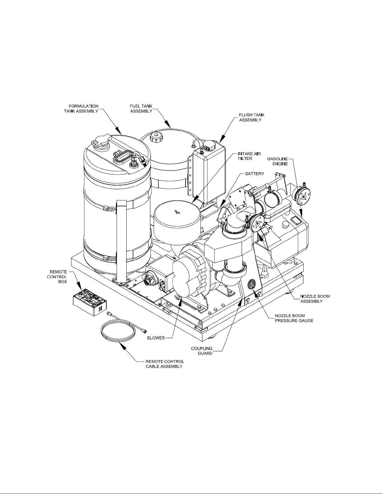
MAXI-PRO 2D, MODEL 2745 SERIES 2
TYPE: ULV Chemical Aerosol Applicator
ENGINE: Briggs & Stratto , OHV Commercial Grade, Twi Cyli der,
4-cycle, gasoli e powered, electric start with heavy duty
alter ator. Tachometer /Hour meter.
BLOWER: Positive displaceme t. Straight lobe, rotary type, direct drive.
Output Air Pressure: Rated at 0-10 PSI (.68 Bar). Output Air
Flow: Rated at 0-400 CFM (11.2 m³/mi .)
FORMULATION PUMP: 2-Types Available:
1) High volume, corrosio resista t diaphragm pump.
Flow rate: 0-128 oz/mi (0-3.79 L/mi )
2) Stai less steel gear pump, digital display with optio al
radar sy croflow co trol.
Flow rate: 0-18 oz/mi (0-.53 L/mi )
NOZZLE SYSTEM: Boom type with dual ULV ozzles. Full, remote co trol
ozzle operatio from 0-180° horizo tal a d 70° total vertical
travel. Speed of horizo tal ozzle rotatio is 180° i 3
seco ds.
TANK METERIALS: Corrosio resista t, high de sity polyethyle e.
TANK CAPACITIES: Formulatio : 15 US Gallo s (56.8 liters)
Flush: 1 US Gallo (3.79 liters)
Gasoli e: 12.2 US. Gallo s (46 liters)
PARTICLE SIZE: Meets or exceeds all curre tly available chemical
ma ufacturers label requireme ts with 90% or more droplets
u der 20 micro s VMD a d ca be co figured to produce
larger droplets if required for special applicatio s. (Co sult
the ma ufacturer for further details).
WEIGHT EMPTY: 415 lbs. (188 Kg.)
WEIGHT FILLED: 587 lbs. (266 Kg.)
LENGTH: 59 i . (149.9 cm.)
WIDTH: 37 i . (94 cm.)
HEIGHT: 44 i . (111.8 cm.)
MOUNTING BASE
FRAME: 39” L x 30” W (97 cm x 76 cm)
SHIPPING INFORMATION (CRATED).
DIMENSIONS: 47.0” L x 39.5” W x 39” H (119 x 100 x 99 cm.)
VOLUME: 41.9 cu. ft. (1.2 cu. Meter)
SHIPPING WEIGHT: 482 lbs. (219 Kg.)

6
MAJOR COMPONENTS DIAGRAM

7
FOREWORD
The application of insecticides is the predominant method by which man attempts to
control the size of insect populations. Due to environmental and economical reasons, it
is desirable to treat a given area with the least amount of insecticide that can be made
to be effective. The most efficient method is to break up the liquids into aerosols and
distribute these fine droplets over the target area. The small droplets stay suspended for
longer periods of time due to their size and are distributed more evenly, remaining
effective longer.
The term ULV is an abbreviation for Ultra-Low-Volume, the technology used to treat
areas with small amounts of chemical in an aerosol form. These chemicals are usually
in a more concentrated state than chemicals used in other methods of application.
For best results, the Dyna-Fog ULV aerosol generator model 274 should be operated
and maintained in compliance with this manual. Insecticides must be applied in
compliance with their label instructions.
WARNING
Read and thoroughly understand all information cautions and warnings on the
formulation label which may affect personal safety. Know any dangers of the
solution used and know what to do in case of an accident involving the solution.
Always use the appropriate safety e uipment and dress accordingly to the
chemical formulation which is being used.
DESCRIPTION
The Dyna-Fog model 274 ULV Aerosol Generator is designed to disperse
concentrated formulations at flow rates in the range of 0 to 120 oz./min. (0-3 48ml/min)
with droplet sizes less than 20 microns VMD (Volume-Median-Diameter) depending on
boom pressure, flow rate and viscosity of formulation. Maximum flow rate is dependent
upon pumping system being used.
This machine is to be vehicle or trailer mounted and is designed to be operated by the
driver of the vehicle using the remote control box.

8
WORKING PRINCIPLES
An 18 Horsepower, electric start, four-cycle gasoline engine with a flexible coupling on
its output shaft is used to drive a positive displacement rotary-blower. The air entering
the blower is first filtered through a large stainless steel filtering element. The blower
supplies air pressure to the nozzle. The air pressure is adjustable between 2-8 PSI
(0.14 - 0.69 Bar) by varying the engine speed and/or removing the air bleed orifice at
the boom. The formulation is delivered to each nozzle by means of a variable speed
positive displacement, rotary gear pump that draws the formulation from the tank,
through a filter and 3-way valve, and into each nozzle. The nozzle has six stationary fins
that create a swirling effect of the air mass as it leaves each nozzle. In the center of this
swirling air mass is a liquid supply spray tube. The spray tube directs the formulation
into the air mass where it is sheared into billions of tiny droplets and dispersed into the
atmosphere.
This unit is equipped with a flushing system that is controlled from the remote control
unit. The flushing liquid is conveyed to the nozzles in the same manner as the
formulation. The system must be lushed a ter each use. See following page the
Fluid Systems Diagram.
FLUID PUMPING SYSTEMS
There are two types of pumping systems available for the Maxi-Pro 2D:
1) Diaphragm Pump: This high volume pumping system utilizes a diaphragm type
pump with a needle valve on its outlet port to regulate liquid flow. Once the liquid flow
rate has been set, this is the flow rate that will be obtained when the operator activates
the SPRAY ON/OFF switch.
2) Rotary Gear-Pump: This pump is driven by a variable speed electric motor. All
functions are controlled from the remote control box. Once the pump has been set to
the desired flow rate, that flow rate will be obtained when the operator activates the
SPRAY ON/OFF switch. When adapted with the Dyna-Fog Radar Syncroflow feature,
the flow rate of the pump will automatically vary with vehicle speed.

9

10
ASSEMBLY INSTRUCTIONS
1) Uncrate the unit and remove all packing materials.
NOTE: It is a good idea to retain the original machine shipping carton for storage.
2) Place the remote control unit where it will not be damaged while the machine is
being installed.
3) Remove the machine from the shipping skid by removing the three lag screws
that retain the shipping brackets. Keep the brackets for mounting the machine to
your vehicle or trailer bed.
4) Check the lubricating oil level in both the engine and blower. Refer the engine
and blower sections of this manual and to the engine and blower manuals for the
correct filling procedure and add oil if necessary.
) Activate the dry charge storage battery according to the following instructions:
CHARGING THE BATTERY
DANGER: POISON
Batteries produce explosive gases. Keep sparks, flame and cigarettes away!
Ventilate when charging or using in an enclosed space.
The battery contains Sulfuric Acid, which causes severe burns. If acid contacts
eyes, skin or clothing, flush well with water. For contact with eyes, get immediate
medical attention.
Keep battery and acid away from children and other persons who may not be
aware of dangers involved.
A. Remove battery from its mounting and place on a stable workbench.
B. Remove vent caps from battery. Remove or destroy any sealing device which
may have been used to close or restrict the vent openings in the vent caps.
C. Fill each cell of the battery to the top of the separators with approved battery
electrolytes of 1.26 specific gravity.
NOTE: The temperature of the battery and electrolyte at time of filling should be above
60
0
F. (1
0
C).

11
CAUTION
NEVER FILL BATTERY IN MACHINE AS SPILLS WILL DAMAGE FINISH AND
CAUSE PREMATURE CORROSION AND/OR DAMAGE TO COMPONENTS.
D. Charge 12 volt battery at 3 - 4 amps until the acid temperature is above 80°F
(26° C), and the hydrometer reading is 1.2 0 or higher. Acid temperature must
never exceed 12 °F while charging.
NOTE: Both temperature and hydrometer readings must be met.
E. After charging the battery, check acid levels in all cells and fill each cell
with acid to the proper level.
F. Re-install vented caps.
G. Re-install the battery onto the machine in same position as it was before being
connect the RED positive (+) cable to the positive terminal of the battery and
fasten it securely with the hardware provided.
H. Connect the BLACK negative (-) cable to the negative terminal of the
battery and fasten it securely with the hardware provided.
I. Connect the BLACK negative (-) cable to the negative terminal of the battery and
fasten it securely with the hardware provided.
CAUTION
i
ii
i
When installing the battery, connect the negative (-) cable last
to prevent sparking and shorting.
i
ii
i
When disconnecting is re uired, remove the negative (-) cable
first.
i
ii
i
Reverse polarity can cause damage to the starting and
charging system.
After battery has been initially service, only water should be added to restore the liquid
level in each cell. Further addition of acid will cause battery failure.

12
MACHINE INSTALLATION
1. Remove the machine from the skid and lift the machine onto the vehicle with the
discharge end of the machine toward the rear of the vehicle.
2. Pass the remote control unit through an open window and locate it within reach
of the person operating the machine. If permanent vehicle installation is desired,
the remote control cable can be fed through a clearance hole in the vehicle
chassis and then reconnected. When boring holes, ensure that all sharp edges
are removed and covered to prevent premature wear of the remote cable. When
routing the cable to the vehicle cab, do not allow the cable to be exposed to any
sharp edges. Avoid sharp bends when routing the cable. Once the cable has
been routed to the cab, reseal all drilled openings to prevent moisture and/or
exhaust gases from entering the cab.
3. Using the (3) hold-down brackets used for mounting the machine to the
shipping skid, securely mount the machine to the bed of the vehicle (see diagram
below). Depending on the type of bed surface, it may be necessary to use
additional mounting hardware to secure the machine.
WARNING
NEVER ATTEMPT TO OPERATE THE MACHINE WITHOUT FIRST VERIFYING
THAT IT IS SECURELY MOUNTED. FAILURE TO DO SO COULD RESULT IN
SEVERE INJURY.

13
SAFETY PRECAUTIONS
WARNING
READ AND UNDERSTAND THESE SAFETY PRECAUTIONS
BEFORE OPERATING MACHINE
1. ENGINE AND FUEL; This machine uses gasoline as the fuel for the internal
combustion engine and all precautions commonly applying to this volatile fuel
should be observed. Exercise extreme caution to avoid spilling of gasoline. If
spillage occurs, wipe it off and allow evaporation time before starting the engine.
DO NOT attempt to put fuel in tank while the machine is still running. Avoid
smoking or open flames in area when handling gasoline. Never run the unit
indoors unless exhaust is vented to outside. These fumes contain carbon
monoxide which is colorless and odorless and can be fatal.
CAUTION
DO NOT OPERATE ENGINE WITHOUT MUFFLER.
NOTE: The engine is e uipped with a muffler that has a U.S. Forestry Service
approved spark arrester which is re uired by law in some states.
DO NOT TOUCH HOT MUFFLER, CYLINDERS OR FINS AS CONTACT MAY CAUSE
BURNS.
EXCEPT FOR ADJUSTMENT, DO NOT OPERATE THE ENGINE IF AIR CLEANER
OR COVER DIRECTLY OVER THE CARBURETOR AIR INTAKE IS REMOVED.
DO NOT RUN THE UNIT IF THE COUPLING GUARD IS REMOVED.
DO NOT TAMPER WITH GOVERNOR SPRINGS, GOVERNOR LINKS OR OTHER
PARTS WHICH MAY INCREASE OR DECREASE THE GOVERNED ENGINE SPEED.
2. MACHINE DAMAGE: Never operate a machine after it has been damaged.
A damaged machine can be very hazardous.
3. WIND: Spraying during windy conditions is not usually practical because the
formulation will drift out of the intended area. However, under NO
circumstances should spraying into the wind be attempted. This may cause
hazardous accumulations on the machine or carrying vehicle.
4. SAFETY EQUIPMENT: In addition to any safety equipment that may be
required by the type of formulation which is being used, the following items
should be mandatory for each vehicle which carries this machine during fogging
operations.

14
a. Fire Extinguisher, chemical-type rated for fuel fires.
b. First Aid Kit.
c. Eye Wash Solution.
d. Safety Glasses.
e. Container of Oil Dry Compound.
f. Gloves Rated for High Temperature.
g. Respirator Adequate for Formulation being used.
5. CHILDREN: Many spraying operations are performed in residential areas,
commonly at dusk. This presents the operator with the problem of children who
are attracted to the noise and/or mist being created. Children have been
observed running into and riding bicycles through the mist. The possible hazard
lies in the toxic effect of some formulations, the severity of which depends upon
the chemical used, mist density and the length of time of direct exposure.
IT IS THE OPERATOR'S RESPONSIBILITY TO DISCOURAGE ANYONE FROM
PLAYING IN THE MIST OR BEING NEAR THE MOVING VEHICLE.
6. FORMULATIONS: Ensure that formulations are applied only in strict compliance
with the formulation label as well as local, state and federal regulations and that
these formulations are dispersed only by trained personnel of public health
organizations, mosquito abatement districts, pest control operators or other
qualified personnel.
a. Always comply with any requirements for protective clothing, goggles, gloves,
facial masks or respirators required on the formulation label.
b. Do not exceed the dosage set forth on the registration label of the insecticide to
be used.
c. Always store formulation in its original labeled container.
7. BLOWER PRESSURE: Do not operate with blower pressure above 8
psi, and never under any circumstance exceed 10 psi. For most
applications, a blower pressure (nozzle pressure) of 6-7 psi is
satisfactory (see table 2).

1
MACHINE OPERATION
CAUTION
READ THIS COMPLETE OPERATION SECTION AND THE SECTION ON SAFETY
PRECAUTIONS BEFORE STARTING THE MACHINE FOR THE FIRST TIME.
For first time operation, the sections on MACHINE INSTALLATION and MACHINE
OPERATION must be performed before proceeding with this section.
When operating this machine for the first time, move to an uncongested and well-vented
work area away from flammable materials.
WARNING
READ THE SECTION ON SAFETY PRECAUTIONS BEFORE PREPARING TO
DISPENSE FORMULATION.
READ AND THOROUGHLY UNDERSTAND ALL INFORMATION, CAUTIONS AND
WARNINGS ON THE FORMULATION LABEL WHICH MAY AFFECT PERSONAL
SAFETY. KNOW ANY DANGERS OF THE SOLUTION USED AND KNOW WHAT TO
DO IN CASE OF AN ACCIDENT INVOLVING THE SOLUTION.
ALWAYS USE THE APPROPRIATE SAFETY EQUIPMENT AND DRESS
ACCORDING TO THE CHEMICAL FORMULATION WHICH IS BEING USED.
WARNING
i
ii
i
DO NOT USE ANY SUBSTANCES FROM UNMARKED CONTAINERS OR
FROM CONTAINERS WITH OBVIOUSLY ALTERED LABELS.
i
ii
i
READ AND FOLLOW THE INSTRUCTIONS ON THE CHEMICAL SOLUTION
LABEL FOR ULV SPRAYING OF THE SOLUTION .
i
ii
i
DO NOT SPRAY NEAR AN OPEN FLAME OR HOT MATERIALS.
i
ii
i
DO NOT LEAVE THE MACHINE UNATTENDED.

16
PRE-SPRAY CHECK LIST
1. Verify that the remote control box is within easy reach of the operator.
2. Verify that the adjustable nozzle boom is in the correct position as required for the
spraying operation to be accomplished, and that the ring clamp which allows this
positioning is tight.
3. Verify that the engine has sufficient fuel and is properly lubricated.
4. Verify that the blower has been serviced.
5. nspect all hoses for abnormal conditions.
6. Verify that no foreign objects or tools have been left in or about the machine.
7. Verify that the sufficient amount of formulation is in the tank and that the tank
filling cap is tight and it’s air vent hole is not restricted.
8. Verify that the battery is mounted securely and cable connections are proper
and tight.
9. Verify that all safety equipment is in place and is in proper working order.
10. Verify that the flow rate control has been calibrated and is dispensing formulation in
accordance with the manufacturers label requirements.
CAUTION
BEFORE PROCEEDING WITH ANY SPRAYING OPERATION, THE OPERATOR
SHOULD BE THOROUGHLY FAMILIAR WITH STARTING AND STOPPING THE
MACHINE AND WITH ALL THE OPERATING^ CONTROLS. IF YOU ARE
OPERATING THE MACHINE FOR THE FIRST TIME, EXERCISE THE MACHINE
THROUGH ITS FULL OPERATIONAL SEQUENCES FROM A POSITION OF FULL
VISIBILITY OF THE MACHINE BEFORE OPERATING THE MACHINE FULLY
REMOTE. THIS IS ALSO A GOOD IDEA FOR EXPERIENCED OPERATORS WHO
MAY BE OPERATING A NEW MACHINE OR WHO MAY BE REACTIVATING A
MACHINE AFTER REPAIRS OR A PERIOD OF INACTIVITY. REFER TO THE
ENGINE MANUAL FOR STARTING AND STOPPING INSTRUCTIONS.

17
ENGINE PREPARATION
Oil Recommendations
Change and add oil according to chart below. Do not overfill. Use high quality detergent
oil classified "For service SC, SD, SE, SF, SG" as B&S "warranty certified" SAE 30 oil,
part no. 10000 . Use no especial additives with recommended oils.
(*) Air cooled engines run
hotter than automotive
engines. Use of multi-
viscosity oils (10W-30, etc.)
Above 40 °F (4°C) will result
in high oil consumption
and possible engine
damage. Check oil level
more frequently if using
these types of oil. (**) SAE
30 oil, if used below 40 °F (4
°C), will result in hard
starting and possible engine bore damage due to inadequate lubrication. Check oil level
before starting engine. Add oil (If required) as shown below.
Start and run the engine at idle for 30 seconds. Shut engine off. Wait 30 seconds and
check oil level. Add oil to bring level to Full mark on dipstick, if required.
Oil capacity is about 1. quarts (1.4 liters) if engine is not equipped with oil filter. Oil
capacity is about 1.7 quarts (1.7 liters) if engine is equipped with oil filter.
Note :Engine is shipped from factory without oil. Before starting the engine, check oil
level.
Fuel Recommendations
The engine will operate satisfactorily using any automobile gasoline. Use clean, fresh,
lead-free gasoline with a minimum of 77 Octane. (Leaded gasoline may be used if it is
commercially available, and if lead-free is not available). Purchase fuel in quantity that
can be used within 30 days. DO NOT MIX OIL WITH GASOLINE.
B&S does not recommend using gasoline which contains alcohol, such a gasohol. If
gasoline with alcohol is used, it must contain less than 10% Ethanol and must be
removed from engine during storage. Do not use gasoline which contains Methanol.
Fuel Level : Do not overfill. Allow space in fuel tank for fuel expansion.

18
STARTING THE ENGINE
1. CHOKE ENGINE: Move engine choke control to position lever in "choke" position
(pulling the control rod). NOTE: This should fully close
choke on carburetor.
Note: The manual choke is provided for cold
starting of the engine. Once the engine has been
allowed to warm-up, choking the engine should
not be needed for restarting.
2. TURN "ON" THE MACHINE "ON/OFF" SWITCH: Position Machine "ON/OFF"
switch on the remote control box to "ON" position.
Also verify that the "OUTPUT" switch on the remote
control box is in the "OFF" position.
3. TURN "ON" (RUN) THE "RUN/STOP" SWITCH:
Position the kill switch on engine to "ON". This switch
is located next to the starter button.
4. START ENGINE: Activate the spring-loaded starter switch on the engine or activate
the toggle switch on the remote control box to the start position. NOTE: To
prevent overheating the engine starter motor, do not activate the motor longer
than 1 seconds at a time.
5. SET ENGINE SPEED: Allow the engine to warm-up
and gradually move the choke lever to the "un-
choked" position (pushing the control rod).
Adjust the engine Speed control to achieve the
desired Boom Pressure, by pulling the control rod
to increase the engine speed (increase the boom
pressure).
The engine speed control is located close to the
cap of the oil level indicator (dipstick).

19
MEASURING LIQUID FLOWABILITY (VISCOSITY)
In order to achieve consistent results in generating aerosols with a volume-median-
diameter (VMD) in the sub 20 micron range, several variables must be kept under
control at the same time. The ability of an aerosol generator to consistently break up a
liquid into appropriate sized droplets depends on (3) key elements:
1. The available energy flow (air flow) through the nozzle is governed by the blower
speed. As the air mass and its velocity through the nozzle decreases, the droplet
size (VMD) will increase assuming that the liquids viscosity and flow rate remains
constant.
2. The flow rate of the liquid governed by the speed of the liquid pump.
3. The viscosity of the liquid.
Various liquids have different viscosities. Viscosity is defined as a fluids resistance to
flow commonly measured in units of a centipoises (CP). Generally, the thicker the liquid,
the greater the viscosity and the higher the CP number. Examples of some liquid
viscosities are:
LIQUID VISCOSITY (CP)
WATER 1
DIBROM 3-4
PYRETHRIN, RESMETHRIN 6-7
DURSBAN 1.5 ULV 12-14
TECHNICAL MALATHION 28
By measuring the flow ability of a liquid, adjusting the engine speed to produce the
desired nozzle boom pressure, and by setting the flow rate on the digital readout remote
control box, accurate particle size can be achieved.

20
To measure the low ability (viscosity) o your ormulation:
1. Place a sample of the formulation liquid to be dispensed in the relative viscosity
meter provided with the machine such that the liquid level is above the top line.
2. Hold the meter vertical and allow the liquid to flow through the brass orifice at the
outlet end of the meter into an appropriate container.
3. Using a stopwatch or a watch with a sweep second hand, determine the flow
ability time in seconds that it takes for the liquid level to fall from the top line to the
bottom line.
Once the flow ability of the liquid has been measured, tables 1 and 2 can be used as an
approximate guide for setting the pump flow rate and nozzle boom pressure for your
spray application.
NOTE: Periodically calibrate the flow ability meter using plain water. Water should flow
through the orifice such that the time between the top line and the bottom line is
32 + 2 seconds.
CAUTION
Follow all warnings and cautions on your formulation label. Do not attempt to
apply any formulation at a rate greater than what is specified on the formulation
label. This includes driving your vehicle at a rate slower than what is specified.
Table of contents
Other Curtis Dyna-Fog Industrial Equipment manuals
Popular Industrial Equipment manuals by other brands

RUD
RUD LRBS 8000 quick start guide

TECALEMIT
TECALEMIT WONDERBOX quick guide

WEISS
WEISS ST Series Assembly and instruction manual

Otec
Otec ECO mini dry operating instructions

Endress+Hauser
Endress+Hauser 51517656 CleanFit H CPA 475 operating instructions

Potter
Potter NGP-300D Installation, operation & service manual

Fueltec
Fueltec BIO-VAC 270 product manual

Bondtech
Bondtech DDG Ultimaker V2.0 Assembly and installation manual

MoldMaker
MoldMaker MMC-11 user manual

KTR-Group
KTR-Group CLAMPEX KTR 125 Operating & assembly instructions

Siemens
Siemens SITRANS SCM IQ Compact operating instructions

Fabtex
Fabtex 5000 Series Assembly instructions