Curtis Dyna-Fog Aire-Mate Hurricane ES 3001-5 User manual

H
Hu
ur
rr
ri
ic
ca
an
ne
e
™
E
ES
S
“Electrostatic” ULV/Mist Sprayer
O
Ow
wn
ne
er
r’
’s
s
M
Ma
an
nu
ua
al
l

Hurricane ES Owner’s Manual 2
Dear Valued Customer,
Thank you for purchasing our product. We take pride in the design, workmanship and
service of all of our products. Designed by Curtis Dyna-Fog, Ltd. and marketed under
our exclusive Aire-Mate line, this machine represents one of the highest quality and
most innovative hand-held spraying products ever produced. Using the latest in
electrostatic technology, the Hurricane ES assures an efficient, uniform application of
water-base products. If properly maintained, this machine will give years of high
performance. During the research and design process, we focused heavily on creating
an efficient, environmentally responsible machine. This is only possible with the help of
many talented people and from suggestions from our customers. If you have any
questions or suggestions concerning our products please contact us at the address
shown below. All Curtis Dyna-Fog products are tested and calibrated at the factory. To
ensure safe and responsible spray applications, please be sure to read and understand
this manual before attempting to operate your machine.
-The Curtis Dyna-Fog Team
Thank you for choosing Aire-Mate®and Dyna-Fog®!
Manufactured for Aire-Mate®by:
Curtis Dyna-Fog ®, Ltd.
17335 US Hwy. 31 North PO Box 297
Westfield, Indiana 46074 USA
Phone: 317.896.2561
Fax: 317.896.3788
www.dynafog.com
US and foreign patents pending
Dyna-Fog, Aire-Mate and Hurricane ES logo are copyrights and trademarks of Curtis Dyna-Fog, Ltd.

Hurricane ES Owner’s Manual 3
‘
Warranty
Limited Warranty for Curtis Dyna-Fog Hand-Held Electric Models
Curtis Dyna-Fog, Ltd. (“Seller”) warrants that the machines it sells will be free of defects in
workmanship and material under normal use and service (as described in the operating manual)
for a period of one year (12 months). Seller’s obligation under this Warranty is limited to
replacing or repairing, free of charge (other than transportation charges or duties which shall be
borne by Purchaser) any defective part or parts of the machine that were manufactured by the
Seller which are returned to the Seller at Westfield, Indiana or are returned to the distributor
from whom Purchaser purchased the machine if such distributor is an authorized repairing
distributor. Components, such as blowers, not manufactured by the Seller will carry only the
warranty of the manufacture of such component and Seller shall have no liability whatsoever for
any defect in any component not manufactured by Seller. Correction in the manner provided
above shall constitute a fulfillment of all liabilities of Seller in any respect to the machines. THE
FOREGOING WARRANTY AND THE OBLIGATIONS AND LIABILITIES OF SELLER
THEREUNDER ARE EXCLUSIVE AND IN LIEU OF AND PURCHASER HEREBY WAIVES
ALL OTHER REMEDIES, WARRANTIES, GUARANTEES OR LIABILITIES, EXPRESS OR
IMPLIED, ARISING BY LAW OR OTHERWISE (INCLUDING WITHOUT LIMITATION ANY
OBLIGATIONS OF THE SELLER WITH RESPECT TO FITNESS, MERCHANTABILITY AND
CONSEQUENTIAL DAMAGES) OR WHETHER OR NOT OCCASIONED BY SELLER’S
NEGLIGENCE. THIS WARRANTY SHALL NOT BE EXTENDED, ALTERED OR VARIED
EXCEPT BY A WRITTEN INSTRUMENT SIGNED BY SELLER AND PURCHASER. If a
warranty card is not returned to Seller (or, in the case of purchases outside of the United States
and Canada, to the importing distributor) or the online registration is not completed within thirty
(30) days of purchase, proof of purchase must be provided to Seller (or, in the case of
purchases outside of the United States and Canada, to the importing distributor) when
submitting the machine for repair. If the date of purchase is not so established and a machine
has been returned to the Seller, Seller will return to Purchaser, at Purchaser’s expense, the
machine unless payment arrangements are made for the repair of the machine at the Seller’s
then-current prices.

Hurricane ES Owner’s Manual 4
Table of Contents
Page
1.0 Main Components Diagram……………………………………………………. 5
2.0 Safety Precautions……………………………………………………………… 6
2.1 Additional Safety Precautions…………………………………………. 7-8
2.2 DO’s and DONT’S………………………………………………………. 9-10
3.0 Specifications …………………………………………………………………… 11
4.0 Principles of Operation…………………………………………………………. 12
5.0 Flow Rates, Droplet Sizes and Applications…………………………………. 13-14
5.1 Insect Control……………………………………………………………. 13
5.2 Odor Control……………………………………………………………... 14
5.3 Disinfecting…………………………………………………………….… 14
6.0 Maintenance…………………………………………………………………….. 15
6.1 Replacing the 3-Prong Electrode……………………………………… 15
6.2 Removing the Metering Valve (Accessing the Formulation Filter)…..16
7.0 Troubleshooting……………………………………………………………….… 17
8.0 Electrical Schematic…………………………………………………………..… 18
9.0 Hurricane ES Exploded Parts Diagram………………………………………. 19-22
9.1 Hurricane ES Parts Listing……………………………………………... 20-21
9.2 Hurricane ES Valve Assembly Diagram and Parts Listing…………. 22
10.0 Hurricane ES Carrying and Storage Bag……………………………………… 23
11.0 Machine Labels………………………………………………………………….. 24
12.0 Noise Level Comparison Chart………………………………………………… 25

Hurricane ES Owner’s Manual 5
1.0
Main Components Diagram-
H
Hu
ur
rr
ri
ic
ca
an
ne
e
E
ES
S
Liquid Metering
Valve
Formulation
Tank
Fill Cap
Power and
Electrostatic
Indicator Light
3 Air Assist
Nozzles
Electrostatic
Charging Ring
(Collector)
Adjustable
Locking Handle
High Capacity
Blower

Hurricane ES Owner’s Manual 6
2.0
Safety Precautions
(It is the Operator’s responsibility to read and understand the Cautions and Warnings in
this manual before attempting to operate the machine.
Important: The Hurricane ES has been designed and engineered to be very safe during normal
operation. As with all AC powered equipment, certain safety precautions should be taken. Please
read the following WARNINGS before operating the machine. UNDERSTAND THESE SAFETY
PRECAUTIONS BEFORE OPERATING MACHINE. FAILURE TO PROPERLY FOLLOW THESE
PRECAUTIONS MAY LEAD TO A FIRE, EXPLOSION, OR ELECTRICAL SHOCK HAZARD.
WARNING
Always have the machine serviced by a professional, qualified representative. Never attempt to
service the machine or access its internal components while it is plugged into an electrical outlet.
To avoid electrostatic shock, do not touch
the metal charging ring or 3-prong electrode
located at the nozzle while the machine is
operating.
Charging Ring (Collector)
3-Prong Electrode (Emitter)

Hurricane ES Owner’s Manual 7
2.1
Safety Precautions (continued)
This machine contains an
electrostatic device that may
interfere with sensitive
medical devices such as
pacemakers, defibrillators, or
similar devices. DO NOT
operate this machine or
stand within 10 feet (3
meters) if you use any such medical devices. Contact your physician prior to operation if you are unsure
if this machine will interfere with your medical device.
This machine contains an electrostatic device that may
cause an electrical shock if not properly grounded.
Always use a three (3) prong grounded extension cord at
the ratings shown in the table when using an extension
cord. In addition, always maintain contact with the handle
during operation to ensure proper grounding.
Always hand carry the machine during
operation so that your hand remains in
contact with the grounding strip located
beneath the carrying handle. Leaving the
machine operating unattended can enable a
buildup of electrostatic charge that can cause
a static shock/spark. Note: Objects in the
vicinity of the machine may develop an
electrostatic charge during operation)
Grounding Strip
Carrying Handle
FIGURE 1
FIGURE 2

Hurricane ES Owner’s Manual 8
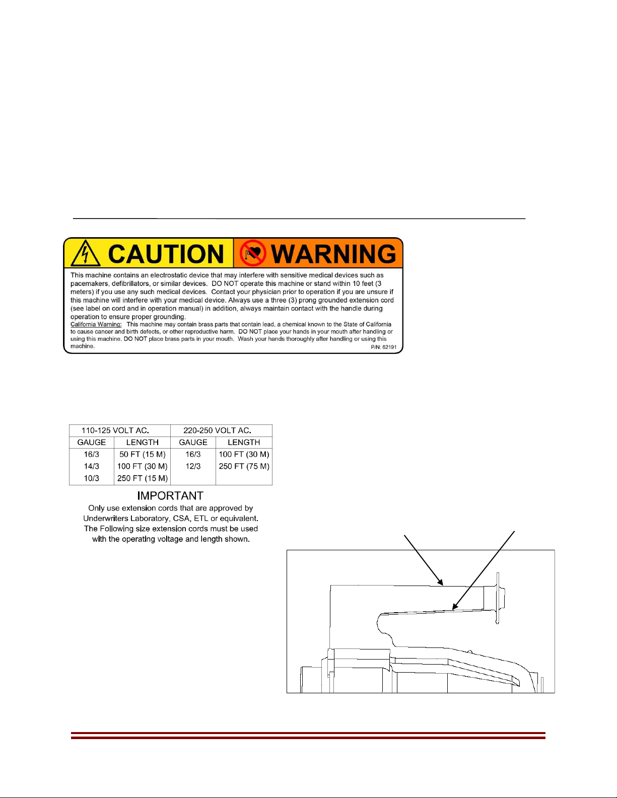
California Warning: This machine contains lead, a chemical known to the State of California to cause
cancer and birth defects, or other reproductive harm. DO NOT place your hands in your mouth after
handling or use of the machine. DO NOT place any brass parts in your mouth. Wash your hands
thoroughly after handling or using this machine.
2.1
Safety Precautions (continued)
WARNING
READ AND UNDERSTAND THESE SAFETY PRECAUTIONS BEFORE OPERATING
MACHINE. FAILURE TO PROPERLY FOLLOW THESE PRECAUTIONS MAY LEAD
TO A FIRE, EXPLOSION, OR ELECTRICAL SHOCK HAZARD.
1. Electric Power. This machine uses electrical power at common commercially available
voltages. When directly contacted, such voltages are hazardous to human life. All precautions
commonly applicable to the use of the electric power general are applicable to the use of this
machine. This machine is designed to operate from three wire power systems where one of
the wires is a safety ground. Use a GFCI (Ground Fault Circuit Interrupter) power outlet
whenever possible. Do not disconnect the safety ground or use extension cords or “cheater”
plugs to connect this machine to a two-wire system. This defeats the purpose of the safety
ground and may result in a hazardous electrical shock condition. This machine must be used
with a 3-prong grounded extension cord plugged into a grounded electrical supply.
When making adjustments on the machine, use an area or workbench that is dry and not
electrically conductive. Dry, natural wood and plastics are generally non-conductive at the
working voltages of this machine. Metals are usually conductive. Do not probe inside the
machine.
Extension cords must be properly sized and rated for the voltage, current, and LENGTH of an
individual cord. Consult the nameplate current and voltage rating of your machine and the
marked rating of the extension cord. A single extension cord only should be used. When two
or more extension cords are placed in series, the rated current carrying capacities of the cords
may no longer be valid. If an extension cord gets warm to the touch, discontinue its use and
obtain a cord with a higher current rating. Improper extension cords are not only hazardous,
but may result in poor machine performance due to excessive voltage drop.
2. Formulations. Many formulations are combustible; that is, they all can be caused to burn.
This is true of even high flash point or “no” flash point formulations (fine particle dust in a grain
mill has “no” flash point). A combustible liquid vapor can more easily be ignited because it
more readily forms a uniform mixture with the air, which contains the oxygen needed for
combustion. However, fine particles of combustible liquids or solids suspended in the air very
closely spaced are capable of propagating flame from one to another once ignition starts. A
good analogy is the grain mill explosion. Although the fine particle dust in a grain mill has “no”
flash point, the phenomena of the grain mill explosion is an all too common occurrence. While
a high flash point or a “no” flash point liquid formulation will ignite far less readily than a low
flash point liquid; and for this reason is strongly advocated, the high or “no” flash point

Hurricane ES Owner’s Manual 9
formulation can ignite if the proper conditions exist. These conditions are basically two: 1) a
sufficient volume of liquid in the form of fine particles suspended in the air; and
2) A sufficiently high energy source of ignition
2.1 Safety Precautions (continued)
3. Aerosol Concentration. It has been fully established that an acceptable level of liquid in
the atmosphere is one gallon per 50,000 cubic feet (2.7 liters per 1,000 cubic meters). There is
a safety margin of at least 5 to 1 in this figure.
4. Aerosol Ignition. If a combustible atmosphere is established or a combustible deposit is
laid down, a source of ignition may cause a fire. Sources of ignition can be gas or oil pilot
lights or sparks from electrical controls. Therefore, it is strongly recommended that all such
sources be eliminated by extinguishing all pilot lights and turning off all unnecessary electric
power. To avoid danger of fire or explosion in an enclosed space, the enclosed volume
fogging time and required formulation volume should be carefully calculated. While operating
the machine, always carry the machine by the carrying handle to ensure that you are properly
grounded.
5. Proper and Improper Use. The following rules apply to the operation of this machine:
2.2
Read the entire manual before operating the machine and pay particular attention to all
CAUTIONS AND WARNINGS.
▪Only use water-base formulations with this machine
▪Store formulation in its original labeled container.
▪Only use a 3-prong grounded extension cord which is properly rated for voltage,
current, and length and which is free from nicks, cracks, and other signs of prior abuse.
For lengths up to 100 feet, (30.5 meters) cords with No. 12 AWG wire are usually
adequate.
▪Turn off sprayer before unplugging. Unplug by grasping the plug. Do not pull on cord to
unplug. Do not unplug machine with wet hands.
▪Replace damaged or worn electric cord immediately.
▪Turn the flow valve CLOCKWISE to the OFF position after each spray application while
the motor is still operating to allow clearing of the lines. This will also prevent a possible
siphon effect if the unit is ever accidentally knocked over with the valve remaining open.
▪Always comply with any requirements for protective clothing, goggles, gloves, facial
masks, or respirator required by the formulation label.
DO

Hurricane ES Owner’s Manual 10
▪Ensure that formulation is applied only in strict compliance with the formulation label as
well as local, state, and federal regulations.
2.2
Safety Precautions (continued)
Do not spray flammable liquids near open flame or other source of ignition.
Do not use oil-base or flammable formulations with this machine.
Do not use a machine that is broken or damaged in any way.
Do not alter the machine by adding or removing parts.
Do not restrict the motor blower inlet area.
Do not tamper with the output nozzle or 3-prong electrode and charging ring (Collector).
Do not allow the machine to operate unattended.
Do not stand in water or hold over water while operating machine.
Do not allow the power cord or extension cord to be submersed in water
Do not use outdoors when it’s raining.
Do not apply more than one gallon of formulation per 50,000 cubic feet (2.7 liters per 1,000
cubic meters enclosed space). Exceeding this concentration is both hazardous and
wasteful.
Do not touch the 3-prong electrode while the machine is operating
DO NOT

Hurricane ES Owner’s Manual 11
3.0
SPECIFICATIONS
Description:
The Hurricane ES™ machine is an electrostatic “Cold Fog” ULV/Mister that utilizes a 3-nozzle
air-assist design. This device is intended for applications of Water-Base formulations. The body
and tank are made of high-density chemical resistant polyethylene. The applicator is useful for
dispensing most chemicals which are labeled for aerosol or mist applications such as
disinfectants, deodorizers, germicides, insecticides, etc., in locations such as hospitals, schools,
nursing homes, greenhouses, stables, warehouses, homes, and farm buildings. The particle
sizes generated range from 10 to 50 microns VMD, obtained using water. Machine output and
particle size are dependent upon the viscosity of the liquid being dispensed. See table 2 for
particle size vs. valve setting (flow rate).
Hurricane™ES Model 3001-5 (120 VAC)
Hurricane™ ES Model 3001-6 (240 VAC)
Motorized Blower:
High efficiency Motor/Blower
Brush Life: Approximately 1000 hours
Electrostatic Power Supply:
120 or 240 Volt AC,
Current Draw:
120V AC 220V AC
6.85 Amps 3.40 Amps
50/60 Hz 50/60 Hz
Nozzle Type:
Professional grade electrostatic, 3 nozzle, air assist
(Vortical type)
Droplet Size:
10-50 Microns VMD (adjustable)
Flow Rate:
0-9.5 oz/min (0-281 ml/min) using water
Spray throw distance*: 30-50 feet (9–15 meters)
*Distance is based on indoor use and will vary depending on
droplet size and formulation type. Smaller droplets (i.e. 20
Microns) can carry much greater distances than larger
droplets.
Tank Capacity:
1 US Gallon (3.78 liters)
Tank Material:
High Density Polyethylene
Weight Empty:
7.5 lbs. (3.4 kg)
Shipping Information:
16.5” L X 12.5” W X 18.5” H
42 cm X 32 cm X 47 cm
H=16.5 in.
(42 CM.)
D= 10 in.
(25.4 CM.)
1 US Gallon (3.8 L)
Tank Capacity
FIGURE 3

Hurricane ES Owner’s Manual 12
4.0
Principles of Operation-
H
Hu
ur
rr
ri
ic
ca
an
ne
e
E
ES
S
This machine consists of a motor/blower assembly, high voltage power supply, charging
ring and electrode, blower housing, a nozzle, formulation tank and metering valve. The
blower is a two-stage centrifugal compressor driven by a universal motor operating at a
speed of 20,000 rpm. The blower moves a large amount of air through the nozzle
system. The nozzle has six (6) stationary fins, which direct the air to create a swirling
effect of the air mass as it leaves the nozzle. In the center of this exiting swirling air, a
liquid supply spout tube injects formulation. The liquid is delivered to the nozzle by a
negative pressure at the nozzle caused by the exiting air mass. The flow rate is
controlled by a one turn precision metering valve located at the formulation tank.
Generally, the sizes of the output droplets increase with increasing flow rates and with
increasing viscosity of the liquid being dispensed.
After the nozzles shear the formulation into billions of droplets, the droplets are
dispersed into the atmosphere. As the droplets exit the nozzles they pass through an
“electrostatic ion field”. This field is created using the combination of a high voltage
power supply, an emitting electrode and charging ring (Collector). The result is billions
of electrostatically charged droplets that gravitate to neutral objects to form a uniform
coverage. The various components are identified in the fluid systems and major
components diagrams.

Hurricane ES Owner’s Manual 13
5.0
Flow Rates, Droplet Sizes and Applications
Liquid flow rate of the Hurricane ES is created by the suction caused by the design of the 3-
nozzles. The Flow rate is regulated by adjusting the metering valve. The liquid flow rate can be
increased by rotating the metering valve knob counterclockwise and decreased by rotating it
clockwise. There are three flow indicator marks on the side of the tank that designate position 1,
position 2 and position 3. Flow rates are shown for these respective positions below. All flow
rate information is based on using water with a temperature of 70 degrees F (21 C). Increasing
the liquid thickness (viscosity) will decrease flow rate and can increase droplet size. This is
because thicker, more viscous liquids are more difficult to atomize. As a rule, thinner liquids
with a lower viscosity atomize easier and flow at higher rates. Refer to the table below for
approximate flow rates and droplet sizes at the various valve settings. Droplet sizes are shown
in microns VMD (Volume-Median Diameter). The VMD is an industry standard and represents
the “middle point” of the spray droplet spectrum of the liquid being applied.
Important: To maximize electrostatic efficiency, only use Water-Base formulations with the
Hurricane ES. Warning: Never use oil-base or flammable formulations with this machine! To
prevent damage to sensitive objects or surfaces like wood finishes, carpeting, upholstery,
etc…do not over apply the formulation being sprayed. If in doubt, always perform a spray test
on a small area to check the effects prior to doing the actual spray treatment.
5.1 Insect Control
Depending on the target insect, droplets are generally generated in the 10-30 Micron range so
that even with some evaporation and settling time, the droplets remain in the correct range for
FIGURE 4
(Collector)

Hurricane ES Owner’s Manual 14
optimal air born suspension and insect impaction. In dry climates evaporation will tend to cause
droplets to “shrink”. Therefore it may be necessary to increase flow rate to get adequate
coverage. The smaller the droplet size the greater the number of droplets that are created. For
example: If 1 milliliter of spray is dispersed as 20 Micron droplets, there will be 239 million
droplets produced. For the same spray mixture using 100 micron droplets, only 1.91 million will
be produced. The large quantity of droplets greatly increases the chances of contact being
made with the insect.
According to the WHO Pesticide Evaluation Scheme, the time required for a droplet to fall 10
meters is defined in Table 1 below.
Droplet Size (Microns)
Time to fall 10 meters
Droplet Density (no/cm3)
1
93.7 hours
19120.0
5
3.7 hours
152.0
10
56 minutes
19.2
20
14 minutes
2.38
50
135 seconds
0.150
100
36 seconds
0.0192
The recommended droplet for Mosquito control is 10-20 Microns. For Fly control approximately
30 Microns. For Bedbugs, spiders and other crawling insects where a slight residual is desired,
20-40 Microns droplets are affective depending on insect type and type of formulation being
used.
Flow Rates, Droplet Sizes and Applications (cont’d)
5.2 Odor Control
Depending on the type of environment and odor source, droplets for controlling odors can be in
the 20-30 Micron range and even larger if a “residual affect” can be tolerated.
5.3 Disinfecting
Disinfectants are designed to be applied to non-living objects to destroy microorganisms.
Typically a disinfectant for objects or surfaces is more affective when applied in the 30-50
micron range. However, smaller size droplets in the 10-20 micron range can be effective when
targeting microorganisms suspended in the air.
TABLE 1

Hurricane ES Owner’s Manual 15
6.0
6.0
6.0
Maintenance
1. Periodically clean the formulation tank using a hot water/detergent solution. Fully
open the machine valve and operate the machine for 3 to 5 minutes, flushing the
solution through the valve, lines and nozzle.
2. Examine the electrical cord for evidence of damage and replace any damaged
FIGURE 5
Valve Knob
Formulation Tube
Detail “A”
See Detail “A”
Approximate flow rates for the valve position
settings are as follows:
Position Flow rate* Droplet Size (VMD)
1 6 oz/min (177 ml/min) 10-20
2 7.5 oz/min (222 ml/min) 20-30
9.5 oz/min (281 ml/min) 30-50
*Flow rates shown are approximate and will vary depending on
liquid viscosity and temperature.
Important: Always spray responsibly. This device is designed to
dispense formulations in a SPRAY (Cold Fog). Many of the
formulations which may be dispensed with this machine require
registration with or approval by various government agencies.
Always calibrate your machine to the proper flow rate in accordance
with the formulation labels recommended rate prior to doing any
spray application.
TABLE 2

Hurricane ES Owner’s Manual 16
cord immediately.
3. If it becomes necessary to disassemble the Machine for cleaning, be careful not
to damage the taper of the valve stem, as this will affect the flow
positions/calibration of the machine.
4. Clean the Air Intake Filter after every application. If the filter gets saturated (wet
and dripping) while the machine is working, stop the machine and clean the filter.
5. After 700-800 hours of operation, carefully remove the blower assembly and
examine the brushes and the commutator bars of the blower motor. If the
brushes are worn out or show signs of damage, have the Blower Assembly
replaced by a qualified service center.
6 After every 25 hours, inspect the three-pronged electrode for damage and wear.
The electrode is made of an extremely durable exotic metal. If the electrode
becomes damage, it may be necessary to replace it. Each machine is shipped
with one spare electrode (Electrode P/N-62172).
6.1
Replacing the 3-Prong Electrode
Step 1) Depending on various operating conditions, after several hours of
operation the 3-prong electrode may begin to show signs of wear. Visually
inspect the electrode after every 25 hours of operation and look for signs of
wear around the edges. If the electrode becomes worn or damaged, proceed to
step 2.
Step 2) Using a Phillips screwdriver, loosen the center mounting screw by
rotating it counterclockwise. Remove the screw and the damaged or worn
electrode.
Step 3) Install a new electrode (1 spare electrode was shipped with your
machine, P/N-62172) making sure that the “3-Prongs” are pointed toward the
center of each nozzle and re-install the Phillips head screw. Do not over tighten
the screw.
6.2
Removing the Metering Valve (Accessing the Formulation Filter for Cleaning)
Always disconnect the main power cord
before attempting to service the machine.
3-Prong Electrode
Always disconnect the main power cord
before attempting to service the machine.
FIGURE 6

Hurricane ES Owner’s Manual 17
Steps for removing the metering valve and formulation filter
1) Using the 5/16 allen wrench
provided with your Hurricane ES,
loosen the set screw located in the
knob assembly, and remove the
knob assembly.
2) Using a flat blade screw driver, push
the plastic drive rivet out of the
formulation tank (See diagram “A”).
3) Using the flat blade screwdriver,
gently pry the valve body assembly
out of the formulation tank cavity.
Note: The formulation pick-up tube and
filter will be attached to the valve body
assembly. Pull these items completely
out of the formulation tank and clean
with warm soapy water.
Steps for re-installing the metering valve and formulation filter
1) After cleaning, place the valve body assembly back into its cavity in the formulation tank.
Make sure that the valve body is seated completely down inside the cavity of the plastic
tank. Use a small hammer to press the drive rivet back into the formulation tank. The drive
rivet serves as a stop for the valve assembly as well as a retainer to keep the valve assembly
from coming out of formulation tank.
2) Once you have the drive rivet back in place, turn the valve stem
clockwise until it stops. When the valve is totally shut (in the
“OFF” position) place the knob assembly onto the valve stem.
Position the knob assembly so that the tab comes in contact
with the drive rivet (see diagram “B”). Tighten the set screw in
the knob assembly with the 5/64 allen wrench. Be careful not
to over tighten the set screw.
3) After the knob assembly is tightened, apply a small amount of sealant to the head of the set
screw. Applying a non-conductive sealant will help to prevent the possibility of receiving a
static discharge/shock when touching this part of the knob.
7.0
(Top View of Metering Knob)
DIAGRAM “B”

Hurricane ES Owner’s Manual 18
Troubleshooting
Symptom
Possible Cause
Corrective Action
No liquid is flowing from the
nozzles or spray is sporadic
•Clogged liquid filter
•Tubing connections are
loose or tubing is
cracked
•Air is entering the liquid
system
•Liquid level in tank
•Remove the metering
valve from the tank (see
Fig. )
•Inspect all tubing
connection and replace
tubing if necessary
•Look for “bubbles” in the
liquid carrying tubing
indicating the source of
the air entry point and
tighten connection or
replace tubing
•Refill tank
Low air flow from nozzles
•Clogged air intake filter
•Remove foam air filter at
rear of housing and
wash using soap and
warm water
Unit will not operate when switch
is in the “On” position (lighted
on/off switch not glowing).
Blower is not running.
•No power at electrical
receptacle
•Bad blower/motor
assembly
•Defective on/off switch
•Loose wiring
connections on blower
•Check power cord
connections and inspect
cord for damage.
Replace power cord if
necessary.
•Replace the blower
motor and motor gaskets
•Replace switch
•Have unit serviced by a
qualified representative
Spray is dripping from the front
of the machine
•Too high of flow rate
•Reduce the metering
valve setting
Static shock occurs when touching
Charging Ring, (Collector) or 3-
prong electrode (Emitter), or metal
surfaces near the metering valve.
Also, static can build up on metal
objects in close proximity of the
machine during operation.
•Static discharge- the
machine is designed to
create this charge so this is
a normal function. Move
any metal container holding
flammable items out of the
vicinity of the machine.
•Do not touch charging ring
or electrode during
operation. Always carry the
machine by the handle to
ensure that you are
properly grounded.
Important: When dealing with any service or repair issue that requires accessing the inside of the blower housing, always
have the machine serviced by a qualified factory representative. Call 317-896-2561 for a qualified service center near you.

Hurricane ES Owner’s Manual 19
8.0
Electrical Schematic Diagram for 110V and 220V

Hurricane ES Owner’s Manual 20
9.0
Hurricane ES Exploded Parts Diagram
This manual suits for next models
1
Table of contents
Other Curtis Dyna-Fog Paint Sprayer manuals
Popular Paint Sprayer manuals by other brands

Larson Electronics
Larson Electronics IND-MD-DF-ESF-R3 instruction manual

Birchmeier
Birchmeier Vario-Matic 1 P operating manual

WALTHER PILOT
WALTHER PILOT PILOT 2K Bonding operating instructions

C.A. Technologies
C.A. Technologies Tomahawk TG Product information

Graco
Graco Magnum 261825 Operation manual

Grupo Sanz
Grupo Sanz PULMIC ANIMAL TRACK manual