Curtis Dyna-Fog TWISTER XL 3 4 Series Owner's manual

1
TWISTER
TM
XL 3
MODEL 3950 SERIES 4 MOTORIZED KNAPSACK ULV SPRAYER
17335 U.S. High ay 31 North
Westfield, Indiana, U.S.A.
.dynafog.com
Instruction Manual For Installation, Operation and Maintenance
Manufactured by Curtis Dyna-Fog
®
, Ltd.

2
TABLE OF CONTENTS
Forward. 3
Machine Specifications.. 4
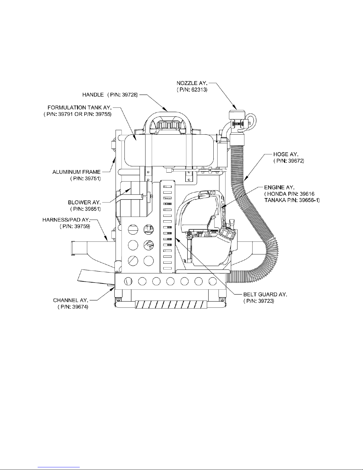
Main omponents Diagram.. 5
Working Principles.. 6
Machine Operation. 7
Pre-Spray hecklist 8
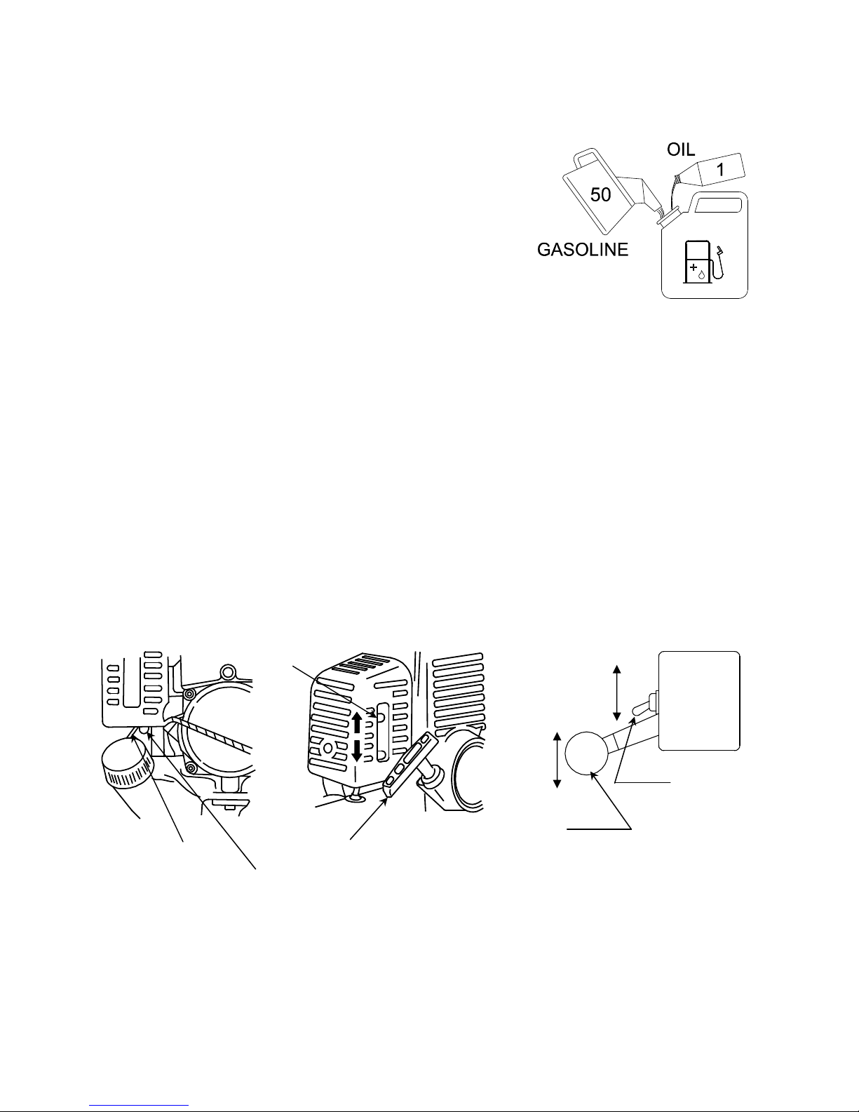
Engine Operation Instructions.. 9-10
Operator Safety 11
On/Off ontrol Valve.. 12
Measuring Liquid Flowability. 13
Flow Rate hart.. 14
Honda Engine Maintenance.. 15
Speed Adjustment.. 15
Air Filter 15
Oil Level heck 16
Oil hange 17
Spark Plug 18-19
Engine Fins... 19
Fuel Filter and Fuel Tank 20
Spark Arrester.. 21
Tanaka Engine Maintenance.. 22
Speed Adjustment.. 22
Air Filter 22
Fuel Filter. 23
Spark Plug 23
Muffler 23
Engine Fins... 23
Blower Assembly.. 24
Inspection of the Blower.. 24-25
Air Filter Assembly 26
Removal and leaning 26
Poly-V Belt and Sheave Drive 27-28
Belt Alignment.. 27-28
Belt Tension.. 29
Flushing the System 30
Preventive Maintenance Schedule 31-32
Flow Rate Verification.. 33
Trouble Shooting Guide.. 34-35
Exploded Machine Diagram and Parts List.. 36-37
Straps. 38
Engine Blower Plate Assembly.. 39-40
Blower Assembly – Exploded. 41
Engine Assembly.. 42
Remote Nozzle Assembly 43
Hose Assembly. 44
Nozzle/Adaptor Assembly 45
Formulation Tank Assembly 46
ontrol Assembly, Throttle.. 47
Flow Regulating Orifices.. 48
Labels.. 49
Dual Nozzle Attachment Diagram and Parts List. 50-51
Installation instructions for Dual Nozzle. 52
Tanaka Engine Information 53-60

3
To the Ne O ner
Dear Valued ustomer,
ongratulations on selecting Dyna-Fog
®
and one of the finest Ultra-Low-Volume (ULV),
machines in the world. The TWISTER™XL 3 is the newest in the Dyna-Fog
®
family of
professional spraying equipment, and represents the latest in portable spray
technology. The TWISTER™XL 3 was developed to provide a powerful yet affordable
multi-purpose machine in a portable, lightweight package. Trials have proven the
TWISTER’s effectiveness, and that operator fatigue caused by the “gyroscopic effect”
associated with other types of hand-held gasoline powered sprayers is virtually
eliminated. Its simple operation and portable design, combined with the ability to
produce variable flow rates make the TWISTER™XL 3 is the most powerful machine of
its type for dispensing liquids in the 20 micron range. Backed by our Quality,
Workmanship and more than 60 years of service, we are confident that the
TWISTER™XL 3 will be a valuable addition to any spraying program.
Thank you for choosing Dyna-Fog
®
.
For ard
The application of insecticides is the predominant method by which man attempts to
control the size of insect populations. Due to environmental and economical reasons, it
is desirable to treat a given area with the least amount of insecticide that can be made
effective. The most efficient method is to break up the liquids into aerosols and
distribute these fine droplets over the target area. The small droplets stay suspended for
longer periods of time due to their size and are distributed more evenly, remaining
effective longer.
The term ULV is an abbreviation for Ultra-Low-Volume, the technology used to treat
areas with small amounts of chemical in an aerosol form. These chemicals are usually
in a more concentrated state than chemicals used in other methods of application.
For best results, the Dyna-Fog ULV aerosol generator model 3950 should be operated
and maintained in compliance with this manual. Insecticides must be applied in
compliance with their label instructions.
WARNING
Read and thoroughly understand all information, cautions and arnings on the
formulation label hich may affect personal safety. Kno any dangers of the
solution used and kno hat to do in case of an accident involving the solution.
Al ays use the appropriate safety equipment and dress accordingly to the
chemical formulation hich is being used.

4
Machine Specifications
TWISTER™XL,
MODEL 3950 SERIES
4
Type
Aerosol Generator, Non Thermal, Insecticide, Ultra-Low-Volume (ULV). Using
ade uate orifice will produce larger droplets.
Engine
Honda GX
-
35
4-stroke, overhead camshaft, single cylinder. Gasoline
consumption: 25.7 oz/hour (760 ml/hour) approximate. Oil Type: 10 W-30. Oil
Capacity: 100 cc (3.4 fl. oz.) Operating Speed: 7,500 RPM, single Microtec™
nozzle.8,500 RPM, optional two Microtec™ nozzles.
Tanaka, Purefire™, 2-cycle, 40 cc, low emission engine. Gasoline
consumption: 26.7 oz/hour (800 ml/hour) approx.Operating Speed: 7,500
RPM, single Microtec™ nozzle.8,500 RPM, optional two Microtec™ nozzles.
Mix Gasoline: Oil 50:1 (refer to label on the Engine).
Blower
High speed Rotary type, 3-Stage, Belt driven, 95 cfm (2.68 m
3
/min)
unrestricted, pressure 3 psi. (.2 bar) max., tangential discharge, steel shaft
with two ball bearings.
Flow Control
Interchangeable restricting orifice to produce different flow rates, from 1.5
oz/min (45 ml/min) to 17 oz/min (500 ml/min).
Nozzle
Single high output Microtec™ nozzle. Optional extra twin nozzle kit for higher
output.
Tanks
Corrosion resistant, high density Polyethylene. Formulation: 1 U.S. Gallons
(3.78 liters). Gasoline: 33.3 oz (1 Lt)
Frame
High Strength Aluminum Tube
Droplet Size
90% of all droplets under 20 Microns (ULV) Mass Media Diameter (VMD)
depending on flow rate and viscosity. When the high flow rate is discharged
through the single nozzle, the machine will produce larger droplets for residual
deposit.
Acc
essories
Visual warning flag with flexible telescopic mast, Flowmeter to determine the
formulation viscosity, 2-cycle oil beaker, funnel.
Weight
27 lbs (12.2 Kg)
Dimensions
14.75 in (37.5 cm) L, 12 in (30.5 cm) W, 22.5 in (57.2 cm) H
Shipping Information (Boxed)
Dimensions
22.5˝ L x 19˝ W x 18˝ H (57.2 x 48.3 x 45.7 cm)
Volume
5.62 cu.ft. (.159 cu. meter)
Weight
37 lbs (16.8 Kg)

5
T ister XL-3 Main Components Diagram

6
AP
AIR
ONE
AIR
TUBE
INJE TION
NOTE:
SE TIONED
NOZZLE FOR
LARITY
HOW THE MI ROTE NOZZLE WORKS
FINS
Working Principles
The TWISTER™XL is powered by a 35cc 4-stroke GX-35 Honda or a 40cc 2-cycle Tanaka PF-
4000 gasoline engine. The TWISTER™XL is designed to take the weight and stress off the
operators hand and wrist to ensure ease and comfort when working. The engine and blower
assembly are mounted on a lightweight, padded
frame that is worn on the operator’s back.
The Engine is used to belt drive a 3-stage High-
Volume Blower. The engine has a “lever type” throttle
control that allows both idle and working engine
operating speeds. The blower supplies air thru a
flexible hose to the nozzle where the air creates
“suction” on the formulation supply tube. The suction
in the formulation supply tube causes liquid to be
drawn from the formulation tank, thru a restricting
orifice, into a shutoff valve and to the nozzle. The
nozzles have six stationary fins that create a swirling
effect of the air mass as it leaves each nozzle. In the
center of this swirling air mass is a liquid supply spray
tube.
The spray tube directs the formulation into the air mass where it is sheared into billions of tiny
droplets (10-20 micron) and propelled thru the air to their target.

7
Machine Operation
CAUTION
READ THIS COMPLETE OPERATION SECTION AND THE SECTION ON SAFETY
PRECAUTIONS BEFORE STARTING THE MACHINE FOR THE FIRST TIME.
When operating this machine for the first time, move to an uncongested and well-vented work
area away from flammable materials.
WARNING
READ THE SECTION ON SAFETY PRECAUTIONS BEFORE PREPARING TO DISPENSE
FORMULATION.
READ AND THOROUGHLY UNDERSTAND ALL INFORMATION, CAUTIONS AND
WARNINGS ON THE FORMULATION LABEL WHICH MAY AFFECT PERSONAL SAFETY.
KNOW ANY DANGERS OF THE SOLUTION USED AND KNOW WHAT TO DO IN CASE OF
AN ACCIDENT INVOLVING THE SOLUTION.
ALWAYS USE THE APPROPRIATE SAFETY EQUIPMENT AND DRESS ACCORDING TO
THE CHEMICAL FORMULATION WHICH IS BEING USED.
WARNING
• DO NOT USE ANY SUBSTANCES FROM UNMARKED CONTAINERS OR FROM
CONTAINERS WITH OBVIOUSLY ALTERED LABELS.
• READ AND FOLLOW THE INSTRUCTIONS ON THE CHEMICAL SOLUTION LABEL
FOR ULV SPRAYING OF THE SOLUTION.
• DO NOT SPRAY NEAR AN OPEN FLAME OR HOT MATERIALS.
• DO NOT LEAVE THE MACHINE UNATTENDED.

8
Pre-Spray Checklist
1. Verify that the operator came easily find and operate the engine kill switch, to stop
the machine, or allow it run.
2. Verify that the steam of the formulation (spray) ON/OFF valve is easy to rotate, to
open and close the valve, remaining in off position.
3. Verify that the engine has sufficient gasoline. If your Twister unit came with Tanaka
engine make sure the gasoline was properly mixed with 2-cycle oil.
4. Verify that the air inlet filter of the blower is clean and unrestricted.
5. Inspect all hoses for abnormal conditions.
6. Verify that no foreign objects and tools have been left in or about the machine.
7. Verify that the sufficient amount of formulation is in the tank and that the tank filling
cap is tight and air vent hole is not restricted.
8. Verify that the formulation line at the machine includes the appropriate flow control
orifice for the viscosity and recommended flow rate of the formulation intended to
dispense, in accordance with the manufactures label requirements.
9. Verify that the belt is in the right position on the sheave,
10. Verify the sight position of straps and belts on the frame before use the machine.
11. Verify that all safety equipment is in place and is in proper working order.
CAUTION
BEFORE PROCEEDING WITH ANY SPRAYING OPERATION, THE OPERATOR
SHOULD BE THOROUGHLY FAMILIAR WITH STARTING AND STOPPING THE
MACHINE WITH ALL THE OPERATING CONTROLS. IF YOU ARE OPERATING THE
MACHINE FOR THE FIRST TIME, EXERCISE THE MACHINE THROUGH ITS FULL
OPERATIONAL SEQUENCES FROM A POSITION OF FULL VISIBILITY OF THE
MACHINE BEFORE OPERATING THE MACHINE ON YOUR BACK. THIS IS ALSO A
GOOD IDEA FOR EXPERIENCED OPERATORS WHO MAY BE OPERATING A NEW
MACHINE OR WHO MAY BE REACTIVATING A MACHINE AFTER REPAIRS OR A
PERIOD INACTIVITY. REFER TO THE ENGINE SECTION FOR STARTING AND
STOPPING INSTRUCTIONS.

9
RUN
STOP
WORKING
IDLE
SPEED
THROTTLE
ONTROL
ENGINE
KILL
SWIT H
Honda GX-35 Engine Operation Instructions
FUEL
heck the fuel level by looking
through the translucent fuel
tank. If the fuel level is low,
refuel in a well-ventilated area
with the engine stopped. If the
engine has been running, allow
it to cool.
STARTING INSTRUCTIONS
Read and understand operation
manual before attempting to
operate machine.
1. Set throttle lever to idle speed. (bottom right diagram)
2. Set ignition switch (engine kill switch) to ON (Run) position (bottom right).
3. Depress priming bulb several times to purge air in the carburetor, until the flows trough
return pipe (bottom left diagram).
4. Pull choke lever upward to choke position/closed (bottom center diagram).
5. Pull recoil starter briskly, taking care to keep the handle in your grasp and not allowing it
to snap back.
6. When you hear the engine want to start, return the choke lever to the run position
(open). Then pull recoil starter briskly again.
Note: If engine does not start,
repeat procedures 4 to 6.
7. After starting, allow the
engine to warm-up 2 to
3 minutes (at idle
speed) before
operating at higher
speeds for fogging
operations.

10
RETURN
PIPE
PRIMING
BULB
HOKE
LEVER
RE OIL
STARTER
RUN
STOP
WORKING
IDLE
SPEED
THROTTLE
ONTROL
ENGINE
KILL
SWIT H
Fig 6
Fig 5
Fig 4
Tanaka PF-4000 Engine Operation Instructions
WARNING
The T ister™ XL is equipped ith a t o-stroke
engine. Al ays run the engine on gasoline, hich is
properly mixed ith oil.
FUEL
Use unleaded gasoline with an 89 octane or higher rating. Use a quality two-cycle at mixing
ratio of 50:1 (right diagram). Always mix gas and oil in a separate clean container. Mix the
gasoline thoroughly before filling the engine fuel tank.
STARTING INSTRUCTIONS
Read and understand operation manual before attempting to operate machine.
1. Set throttle lever to idle speed. (bottom right diagram)
2. Set ignition switch (engine kill switch) to ON (Run) position (bottom right).
3. Depress priming bulb several times to purge air in the carburetor, until the flows trough
return pipe (bottom left diagram).
4. Pull choke lever upward to choke position/closed (bottom center diagram).
5. Pull recoil starter briskly, taking care to keep the handle in your grasp and not allowing it
to snap back.
6. When you hear the engine want to start, return the choke lever to the run position
(open). Then pull recoil starter briskly again.
Note: If engine does not start, repeat procedures 4 to 6.
7. After starting, allow the engine to warm-up 2 to 3 minutes (at idle speed) before
operating at higher speeds for fogging operations.

11
WARNING
As recommended for any machine driven by an internal combustion engine, this
equipment is intended to use outdoor and in a ell ventilated area, in order to
preventing Carbon Monoxide poisoning.
CAUTION
Keep the flexible air hose far a ay from the engine exhaust to avoid damage to
the hose. The nozzle holder is intended to use hen the machine is OFF (for
transportation purposes), and for a short period of time hen the engine is at idle
speed, for easy installation on the back operator.
TO STOP THE MACHINE
1. If the formulation valve is open (ON position), turn it close (OFF) position.
2. Return the throttle control lever to the idle speed (down) position.
3. Move the engine kill switch to the stop (down) position.
OPERATOR SAFETY
Keep all loose items (i.e. lothing, hair, jewelry, etc.) away from all moving parts.
Many of the formulations which can be dispensed with this machine are highly toxic and
require special safety equipment. Read and observe the formulation label safety
precautions, warnings and procedures before operating machine.
Always wear hearing protection.
Never let an inexperience person operate machine.
Do not operate the machine if you are ill, or under the influence of alcohol, drugs or
medication.
CAUTION
Do not start the machine ithout the belt guard and the heat shield cover
installed.

12
Using the Spray On/Off Control Valve
The flow of formulation to the nozzle is controlled by the Spray ON/OFF Valve. The
valve is located between the nozzle and the carrying handle.
The upper drawing shows the
Spray ON/OFF control valve in
open (ON) position, allowing
the flow of formulation from
the formulation tank to the
nozzle. It is recommended to
move this valve to the ON
position only if the machine is
running.
The lower drawing shows the
Spray ON/OFF control valve in
close (OFF) position, stopping
the flow of formulation.
Flow rate can be changed by partially
opening the valve to the desired position.
Flow rates shown in Table 1 are based on
the ON/OFF valve in the maximum open
position.
I PORTANT:
To prevent dripping from the nozzle, turn the
spray valve to close (OFF) before turning
power off.
The Spray ON/OFF valve will provide many
hours of service. With the time, and depending of the corrosive action of the formulation
used, the steam of the valve could begin to be harder to rotate. If the steam is too hard
to rotate, change the valve before it breaks and gets inoperative.
VALVE IN LOSE
(OFF) POSITION
VALVE IN OPEN
(ON) POSITION

13
LINE NO. 2
URTIS DYNA-FOG Ltd.
(FLOWABILITY TIME)
LINE NO. 1 TO LINE NO. 2
FLUID TO DRAIN FROM
OUNT SE ONDS IT TAKES
LINE N0. 1
Measuring Liquid Flo ability (Viscosity)
In order to achieve consistent results in generating aerosols with a mass median
diameter (MMD) in the sub 20 micron range, several variables must be kept under
control at the same time. The ability of an aerosol generator to consistently break up a
liquid into appropriate sized droplets depends on 3 key elements:
1. The available energy flow (air flow) through the nozzle is governed by the blower
speed. As the air mass and its velocity through the nozzle decreases, the droplet
size (MMD) will increase assuming that the liquids viscosity and flow rate
remains constant.
2. The flow rate of the liquid governed by the diameter of the flow control orifice.
3. The viscosity of the liquid.
Various liquids have different viscosities. Viscosity is defined as a fluids resistance to
flow commonly measured in units of centipoises ( P). Generally, the thicker the liquid,
the greater the viscosity and the higher the P number. Examples of some liquid
viscosities are:
LIQUID
VISCOSITY (CP)
Water 1
Dibrom 3-4
Dow MF 3-4
Pyrethrin, Resmethrin 6-7
Dursban 1.5 ULV 12-14
Technical Malathion 28
To Measure the Flo ability (Viscosity) of Your Formulation
1. Place a sample of the formulation liquid
to be dispensed in the relative flowability
meter provided with the machine such
that the liquid level is above the top line.
2. Hold the meter vertical and allow the
liquid to flow through the brass orifice at
the outlet end of the meter into an
appropriate container.
3. Using a stopwatch or a watch with a
sweep second hand, determine the
flowability time in seconds that it takes
for the liquid level to fall from the top line
to the bottom line.
Flowability
Test Meter

14
NOTE: Periodically calibrate the flowability meter using plain water. Water should flow
through the orifice such that the time between the top line and the bottom line is 32
±
2
seconds.
Once the flowability of the liquid has been measured, Tables 1 and 2 can be used as an
approximate guide for setting the Flow ontrol Orifice size for your spray application.
Flow Rate Chart
NOTE: THE FLOW RATES SHOWN
HIGHLIGHTED WILL PRODUCE DROPLETS OF
20 ICRONS (V D) OR LESS (ULV). USING
FOR ULTIONS WITH HIGHER VISCOSITY THAN
32 SECONDS WILL REDUCE THE FLOW RATE
BY APPROXI ATELY 20% OR ORE.
WARNING
ALWAYS APPLY FORMULATIONS IN ACCORDANCE WITH THE
MANUFACTURER’S RECOMMENDATIONS.
The flow rate in the Tables 1 and 2 are the average value of several machines tested,
with the nozzle located at the level of the machine base.
The Dyna-Fog
®
Microtec™ Nozzle will produce 90% of the droplets below 20 microns
(ULV) when used at the recommended flow rates. This meets the requirements of all
current chemical labels for controlling flying insects.
When the high flow rate is discharged through a single nozzle the Twister™ XL will
produce larger droplets of 50 microns suitable for applying a residual deposit to
vegetation and any other surface.
NOTE: Always handle and dispose of all chemicals in accordance with the
manufacturers’ instructions and the material safety sheet for the chemical being used.
SINGLE MICROTEC NOZZLE
32 SE ONDS FORMULATION
ORIFI E
NUMBER
FLOW RATE
OZ/MIN ML/MIN
19 1.5 45
28 3.3 100
36 5.3 160
NONE 17.0 500
70 SE ONDS FORMULATION
19 1.23 37
88 SE ONDS FORMULATION
19 1.2 36
DOUBLE MICROTEC NOZZLE*
32 SE ONDS FORMULATION
ORIFI E
NUMBER
FLOW RATE
OZ/MIN ML/MIN
54 12 360
NONE 19.0 570
* OPTIONAL TWO NOZZLE VERSION
TABLE 1 TABLE 2

15
Honda GX-35 Engine Maintenance
Maintenance, replacement, or repair of the emission control devices and systems may
be performed by any non-road engine repair establishment or individual.
In the carburetor, fuel is mixed with air. When the engine is tested at the factory, the
carburetor is pre-set.
Speed Adjustment
When the Twister™ XL is tested at the
factory, the engine working and
minimum speed is basically adjusted.
The working speed for the engine is
7150 rpm (+/- 50 rpm) for single nozzle.
A further adjustment may be required
according to climate or altitude existing
at the place to work with the machine.
To adjust the engine speed, remove the
plastic air cleaner cover from the engine,
loosen the jam nut from the perforated
adjuster screw; to increase the speed,
unscrew the adjuster screw, to decrease
the speed screw in the adjuster screw,
check the speed with a tach meter after
5 or 7 minutes of operation, readjust if
required. Reinstall the plastic air cleaner cover.
Air Filter
The air filter must be cleaned periodically from dust and dirt in order to avoid:
arburetor malfunctions, Starting problems, Engine power reductions, Unnecessary
wear on the engine parts and/or abnormal fuel consumption.
lean the air filter daily or more often if working in exceptionally dusty areas. To clean
the air filter, Press the latch tab on the top of the air cleaner cover, and remove the
cover. Always replace damaged filter elements.
1. lean the filter element in warm soapy water, rinse, and allow to dry thoroughly.
Or clean in nonflammable solvent and allow to dry.
2. Dip the filter element in clean engine oil, then squeeze out all excess oil. The
engine will smoke when started if too much oil is left in the foam.
3. Wipe dirt from the air cleaner body and cover, using a moist rag. Be careful to
prevent dirt from entering the carburetor.

16
4. Wipe dirt from the air cleaner body and cover, using a moist rag. Be careful to
prevent dirt from entering the carburetor.
Oil Level Check
heck the engine oil level before each use, or every 10 hours if operated continuously.
heck the engine oil level with the engine stopped and in a level position.
1. Remove the oil filler
cap/dipstick and wipe it clean.
2. Insert and remove the oil filler
cap/dipstick without screwing it
into the oil filler neck, then
remove it to check the oil level
shown on the dipstick.
3. If the oil level is near or below
the lower limit mark on the
dipstick, fill to the bottom edge
of the oil fill hole with the oil.
To avoid overfilling or under
filling, be sure the engine is in
a level position, as shown,
while adding oil.
4. Reinstall the oil filler cap/dipstick and tighten securely.

17
Oil Change
Drain the used oil when the engine is warm. Warm oil drains quickly and completely.
1. heck that the fuel filler cap is tightened securely.
2. Place a suitable container below the engine to catch the used oil.
3. Remove the oil filler
cap/dipstick and drain the oil
into the container by tipping
the engine toward the oil filler
neck.
Please dispose of used motor oil in
a manner that is compatible with the
environment. We suggest you take
used oil in a sealed container to
your local recycling center or service
station for reclamation. Do not throw
it in the trash, pour it on the ground,
or down a drain.
4. Drain the used oil when the
engine is warm. Warm oil
drains quickly and
completely.
Some oil will remain in the engine after draining. When refilling with fresh oil, start with
less than 2.7 oz (80 cm). Slowly add enough oil to fill to the bottom edge of the oil fill
hole as shown below.
CAUTION
Running the engine ith a lo
or excessive oil level can
cause engine damage.
Reinstall the oil filler cap/dipstick
securely. If any oil is spilled,
make sure to wipe it up.

18
Spark Plug
Recommended Spark Plug: M5H (NGK), MR5H (NGK).
The recommended spark plug is the correct heat range for normal engine operating
temperatures.
For good performance, the spark plug must be properly gapped and free of deposits.
1. Remove the top cover. Loosen the 5 mm hex bolt with a hexagon wrench, then
remove the top cover.
CAUTION
Do not operate the engine hen the
top cover is removed. Do not pull the
recoil starter handle hen the top
cover is removed. You may be injured
from the rotating parts or burned by
the muffler.
2. Disconnect the spark plug cap,
and remove any dirt from around
the spark plug area.
3. Remove the spark plug with a 5/8-
inch spark plug wrench.
4. Inspect the spark
plug. Replace it if
damaged or badly
fouled, if the sealing
washer is in poor
condition, or if the
electrode is worn.
5. Measure the spark
plug electrode gap
with a wire type feeler
gauge. orrect the
gap, if necessary, by
carefully bending the
side electrode. The
gap should be: 0.60 0.70 mm(0.024 0.028 in)

19
6. Install the spark plug carefully, by hand, to avoid
cross threading.
7. After the spark plug is seated, tighten with a 5/8-
inch spark plug wrench to compress the sealing
washer.
8. When installing a new spark plug, tighten 1/2 turn
after the spark plug seats to compress the
washer.
9. When reinstalling the original spark plug, tighten
1/8 1/4 turn after the spark plug seats to
compress the washer.
CAUTION
A loose spark plug can overheat and damage the engine. Overtightening the
spark plug can damage the threads in the cylinder head.
10. Attach the spark plug cap to the spark plug.
11. Install the top cover, and tighten the 5 mm hex bolt securely with a hexagon wrench.
Engine Fins
Inspection:
1. Loosen the 5 mm hex bolt,
then remove the top cover.
2. Disconnect the spark plug
cap.
3. Inspect the engine cooling
fins, and clean out debris if
necessary.
4. Reconnect the spark plug
cap.
5. Install the top cover, and
tighten the 5 mm hex bolt
securely.

20
Fuel Filter and Fuel Tank
CAUTION
A loose spark plug can overheat and damage the engine. Overtightening the
spark plug can damage the threads in the cylinder head.
1. heck that the engine
oil filler cap is
tightened securely.
2. Remove the fuel filler
cap, and drain the
fuel into an approved
gasoline container by
tipping the engine
toward the fuel filler
neck.
3. Pull the fuel filter out
through the fuel filler
neck by hooking the
black fuel tube with a
piece of wire, such as
a partly straightened
paper clip.
4. Inspect the fuel filter. If
the fuel filter is dirty,
wash it gently with
nonflammable or high
flashpoint solvent. If
the fuel filter is
excessively dirty,
replace it.
5. Remove water and dirt
from in the fuel tank
by rinsing the inside of
the fuel tank with
nonflammable or high
flash point solvent.
6. Insert the fuel filter into the fuel tank and tighten the fuel filler cap securely.
This manual suits for next models
1
Table of contents
Other Curtis Dyna-Fog Paint Sprayer manuals