manuals.online logo
Brands
  1. Home
  2. •
  3. Brands
  4. •
  5. Curtis
  6. •
  7. Coffee Maker
  8. •
  9. Curtis Alpha 1D User manual

Curtis Alpha 1D User manual

Rev.8/16/00
ALPHADIGITAL
COFFEE BREWERS
Wilbur Curtis Co., Inc.
S E R V I C E M A N U A L
INCLUDES THE FOLLOWING UNITS:
––
––
–ALPHA 1D ––
––
–ALPHA 2D ––
––
–ALPHA 3D
––
––
–ALPHA 3DR ––
––
–ALPHA 3DL ––
––
–ALPHA 5DR
––
––
–ALPHA 5DL ––
––
–ALPHA 6D CONTENTS 1
1
2
2
2
3
5
7
8
9 - 15
16
17
18
19
20
21
22
23
24
Back Cover
IncludedinthisservicemanualisinformationontheAlpha1D,Alpha2D,Alpha3D,Alpha
3DL,Alpha 3DR,Alpha5DL, Alpha5DR andAlpha 6D. The information is common to all
Alphadigitalbrewersexceptwherenoted.
Alpha Digital . . . . . . . . .
Setup . . . . . . . . . . . . . . . .
Setup Steps . . . . . . . . . .
Brewing . . . . . . . . . . . . .
Coffee Requirements .
Programming . . . . . . . . .
Trouble Shooting . . . . . .
Replacing Membrane .
Care & Maintenance .
Illustrated Parts Lists
Wiring Diagrams
Alpha 1D . . . . . . . . .
Alpha 2D . . . . . . . . .
Alpha 3D . . . . . . . . .
Alpha 3DR . . . . . . . .
Alpha 3DL . . . . . . . .
Alpha 5D . . . . . . . . .
Alpha 3D-61/63 . . . .
Alpha 6D . . . . . . . . .
Alpha 3D - Export . .
Warranty . . .
C
Carton Contents
Automatic Coffee Brewer . . . . . . . . .
Brewcone . . . . . . . . . . . . . . . . . . . . . . .
Paper Filters . . . . . . . . . . . . . . . . . . . . . .
Elbow Fitting, 3/8 X 1/4 Flare . . . . . . . .
1
1
25
1
Qty Item PartNº
Alpha
WC-3621
CR-10
WC-2401
Allproducts manufacturedby the
WilburCurtis Company arethoroughly
inspected at the factory and are
warrantedto befreeof alldefectsand
faultyworkmanship.TheAlphaunit is
packagedfor maximum protectionfor
shipping.
Make sure the shipping carton is not damaged or punctured. Unpack the carton carefully, inspecting the
contents for any damage that may have occurred in transit.
Reportany damageimmediately to thefreight company.
9/6/00 12.2 f-2068revA.p65.p1
ALPHA DIGITAL
The Alpha Digital series of automatic coffee brewers require installation to be in compliance
with all local water and electrical power codes. The Alpha is designed to brew 12 cups at a
time. The Alpha 3D, 3DL and 3DR have three warmer plates that allow up to three decanters to
be kept at serving temperature. The hot water faucet lets you draw hot water for tea, instant
soups, chocolate drinks or cup meals - even during the brew cycle.
Figure1. AlphaBrewingSystem,BasicComponents.
WARMERPLATES
ELECTRONICCONTROL
BOARD
DUMPVALVE
HOTWATER
FAUCET
SPRAYHEAD
BREWCONE
HEATINGTANK
12CUPDECANTER(NOTINCLUDED)
WATERINLET
VALVE
WARMERPLATE
z
z
z
z
z
z
z
z
zz
z
1
CAUTION DO NOT connect this brewer to hot water. Inlet valve not rated for hot water.
TheNationalSanitation Foundation(NSF), requiresthe followingwater hookup:
1. Aquickdisconnectwater connection orenough extracoiled tubing (atleast 2xthe depthof the
unit)sothat themachine canbe movedforcleaningunderneath.
2. Anapprovedflow backprevention device,suchas adouble check valveto be installedbetween
themachineand thewatersupply.
Alphadecanter brewersareshipped withthe power cordconnected inside themachine. The
powercord ends withan electric plughaving two flatblades with around grounding pin,120VAC
currentand 20 amp rating. Some units are ratedfor220 volts. Check the serial plateon the side
of the machine to make sure of the electrical requirements for your unit.
THISEQUIPMENTISTOBEINSTALLEDTOCOMPLYWITHTHEAPPLICABLEFEDERAL,STATE,ORLOCALPLUMBINGCODESHAVINGJURISDICTION.
TheAlphaunit shouldbe locatedon asolid countertop.The countertop shouldbe level.Connect
thewater linefrom the waterfilter tothe unit using¼" coppertubing with aflare fittingat the end.
Sometype ofwater strainer mustbe used tomaintain atrouble-free operation. Inareas with ex-
tremelyhard water, wesuggest thatan EverpureQC7-MH water filterbe installed.Waterfilters may
beordered from the WilburCurtis Company.For customer service call(800) 421-6150.
SETUP
STEPS FOR BREWING COFFEE:
1. Place a paper filter into the brew cone. Pour ground coffee into the filter.
2. Slide the brew cone into place. When pushed in against the stop, the brew cone fits into the slide rails
and centers it under the sprayhead (see Figure 1. illustrating basic components).
3. Place a clean coffee decanter on the warmer plate.
CAUTION - Always use an empty decanter before starting a brew cycle.
4. To start brewing, push in the momentary brew switch, located on the front panel. The brew cycle will
take approximately three minutes to complete. To stop a brew cycle press the ON/OFF button.
CAUTION - Wait for hot coffee to stop dripping from brew cone before lifting decanter.
5. To stop a brew cycle press the ON/OFF button.
The Alpha coffee brewer will produce excellent results using most grades of
coffee available from your coffee distributor. Coffee suppliers can provide coffee
in convenient pre-measured envelopes.
The Alpha coffee brewer is designed for ground coffee; Freeze Dried or Liquid
coffee products will not work.
The Wilbur Curtis Company manufactures bulk coffee dispensers (Models
MCD-7 or MCD-7G) that consistently dispense ground coffee in selected
amounts.
COFFEE REQUIREMENTS
Figure2.MCD-7Coffee
Dispenser
BREWING
2
1. Connect a ¼" copper water line from your facility to the ¼" flare water inlet fitting on the valve, behind
the machine. Water pressure going to the machine must be stable. Use a water regulator to maintain
constant pressure. This brewer works perfectly when water pressures are from 20 to 90 psi.
2. Plug the power cord into an electrical outlet rated at 20A.
3. Turn on the toggle switch behind the unit. The heating tank will start to fill. When the water reaches the
probe, the heating element will turn on automatically.
4. The heating tank will require 20 to 30 minutes to reach operating temperature (200ºF). The READY TO
BREW indicator will light at this time.
5. When water reaches operating temperature, dispense about 12 ounces of hot water through the hot
water faucet to lower the water level in the heating tank. You can also dispense only enough water to
activate the liquid level control.
Setup Steps
3
PROGRAMMING
(ONLY REQUIRED IF FACTORY SETTINGS MUST BE CHANGED)
IMPORTANT These digital brewers are thoroughly tested and programmed at
the time of manufacture.
A few brew cycles may be required for unit to normalize.
ENTERING THE PROGRAM MODE
For all programming functions you must first enter the programming mode as follows:
zTurn OFF the power from the Control Panel by pressing .
zPress and HOLD and press and RELEASE .
MODE #1
zContinue HOLDING until starts blinking; RELEASE.
MODE #2
zContinue HOLDING until stops blinking; RELEASE.
MODE #3
zContinue HOLDING until stops blinking and remains on; RELEASE.
BREW
BREW
BREW
READYTOBREW
READYTOBREW
ON/OFF
ON/OFF
CONFIRM/RESET BREW TEMPERATURE
ENTER THE PROGRAMMING MODE #1:
(PRE-PROGRAMMED FOR 200º F)
zPress for two seconds, then RELEASE.
zwill start blinking. Each blink equals 2º F, starting at 170º (max. temp. 204º F
or 18 blinks).
zTo change Temperature, press and HOLD .
zwill start QUICK flashing. Each QUICK flash equals 2º F. After reaching 204º,
temperature starts over at 170º.
zRELEASE when the desired temperature is reached. The newly set tempera-
ture will now be displayed. To set and exit, press .
BREW
READYTOBREW
ON/OFF
BREW
READYTOBREW
BREW
(Over)
BREW READYTOBREW
4
ENTER THE PROGRAMMING MODE #2:
zwill now start a pattern of LONG and SHORT blinks.
This pattern identifies the number of brew cycles. SHORT blinks indicate
the brew number from 1 to 9. LONG blinks separate 1's, 10's, 1,000's and
10,000's.
READYTOBREW
TO ACCESS PREVENTATIVE MAINTENANCE BREW CYCLE COUNTER
CHANGE BREW VOLUME
IMPORTANT - Before changing the brew volume, place a measuring
container on the brew deck and insert the brew cone.
ENTER THE PROGRAMMING MODE #1:
(PRE-PROGRAMMED FOR APPROXIMATELY 64 OUNCES)
zPress and HOLD until hot water starts running, then RELEASE.
zWhen desired volume is reached, press again to stop the flow.
zTo set and exit, press .
BREW
BREW
ON/OFF
WARMER QUALITY TIMER - Factory Preset to OFF
TO DETERMINE WARMER SETTING AND CHANGE TIME
zWarmer must be ON. Press and HOLD until light goes OFF, RELEASE.
zThe light will start blinking. Count the blinks. Each blink=5 minutes
(maximum 50 minutes).
zAt the end of the cycle, press and hold until the light begins quick
flashing. The cycle will start over after 11 flashes (a setting of 11 flashes is the
OFF position).
zWhen the desired time is reached, RELEASE .
zTo set and exit, press .
WARMER
ON/OFF
WARMER
WARMER
NUMBER
OFBLINKS
1
2
3
4
5
6
7
8
9
TEMPERA-
TURE
170º F
172º F
174º F
176º F
178º F
180º F
182º F
184º F
186º F
NUMBER
OFBLINKS
10
11
12
13
14
15
16
17
18
TEMPERA-
TURE
188º F
190º F
192º F
194º F
196º F
198º F
200º F
202º F
204º F
Table 1.Te mperature Settings
SETS BLINKINGLIGHTPATTERN
1ST
2ND
3RD
4TH
5TH
END 01024
NUMBEROFBREWS
TOTALBREWS
= 4
= 20
= 0
= 1,000
= 0
4x1
2x10
0x100
1x 1,000
0x10,000
Table 2. Exa mple of Brew Counting Code
TROUBLE SHOOTING
POSSIBLE CAUSE SOLUTION
Make sure the unit is receiving enough water pressure. Open
the water line. Change the filter or filter element.
Turn the brewer off. Disconnect wires from water inlet coil
terminals and connect a power cord to the terminals. Plug cord
into a 120V outlet and verify if water flows when plugged in
and stops when power is disconnected. If valve fails this test,
replace valve.
When the water level gets below the probe tip, water should
automatically refill the tank. If not, pull wire off the probe
terminal. Water should now start flowing into the tank. If not,
check the control board of the microprocessor assembly (see
step 4), or inlet valve (step 5, below).
Pull wire out of probe terminal. With a voltmeter, check voltage
at the water inlet coil terminals. This should read 110-120
volts. If no voltage is present, check control board. Make sure
the control board is energized on terminals WHT & BLK. Lack of
power to these terminals will indicate a defect within the
circuit board. Replace the microprocessor assembly.
Check for loose connections at terminals.
PROBLEM: WATER DOES NOT FLOW INTO HEATING TANK
1. Water line turned off
or water filter needs
changing
2. Water inlet valve coil
burned out
3. Grounded probe
4. Defective or burned
out control board
CODE:
5
PROBLEM: WATER IN HEATING TANK OVERFLOWING
POSSIBLE CAUSE SOLUTION
Unplug the unit and observe water level. If water continues to
flow into tank, clean or replace valve.
Pull wire off from probe terminal. Touch the metal body of the
heating tank with the end of this wire (to ground the wire). If
water stops flowing, try cleaning the probe. Probe may have to
be replaced.
The control board must be grounded. Check for loose connec-
tions at the terminals. Make sure the grounding wire is securely
fastened to the chassis.
5. Defective water inlet
valve
6. Probe limed up
7. Non-grounded or loose
terminal connections at
control board
CODE:
ANYSERVICEDONEONTHISUNITMUSTBEPERFORMEDBYAQUALIFIEDSERVICETECHNICIAN.
ERROR CODES: All Alpha Digital brewers contain various safety features in the electronic circuitry that shut down the
functions of the unit in the event of a system failure. Error codes are signalled by the BREW READY light blinking. Decipher-
ing the code:
WATER LEVEL PROBLEM 3 LONG AND 1 SHORT
TEMPERATURE SENSOR PROBLEM 3 LONG AND 2 SHORT
6
TROUBLE SHOOTING, CONTINUED
PROBLEM: WATER NOT FLOWING FROM SPRAYHEAD
SOLUTION
POSSIBLE CAUSE
Remove sprayhead and clean. Clean the sprayhead fitting.
Check water level in tank. If water is not flowing into the tank,
review steps 1 thru 4, previous page.
Check the continuity between terminals WHT & BREW VLV.
When the BREW button is pressed, there should be solid conti-
nuity between these two terminals. If not, replace the mem-
brane control panel (see the instructions below).
Make sure the board is receiving 110 to 120 volts at terminals
BREW VLV and WHITE when BREW switch has been pressed.
There should be 110 to 120V going to the dump valve. If not,
then the control board is faulty.
If the control board is functioning properly (step 14), check the
dump valve. Measure voltage across the two terminals of the
valve coil. You should read 110 to 120 volts. Check also for
clogging or lime deposits. Clean if possible. Replace valve or
coil.
12. Sprayhead clogged
13. Water level is too low
in heating tank
14. Defective control board
15. Defective dump valve
or coil
CODE:
PROBLEM: WATER IN TANK DOES NOT GET HOT
OR WATER TEMPERATURE TOO LOW
POSSIBLE CAUSE SOLUTION
CODE:
Make sure unit is on; power cord plugged in. Toggle switch is
on. Breaker is on.
Remove the sensor and squeeze a dab of silicone compound
(part no. WC-5229) between the sensor and the tank body.
Make sure the fastening nut is secure. Check the wire for
damage.
Check element for continuity and or check with clamp amme-
ter. This should show a reading of approximately 15 amps
(depending on element wattage). If no power is going through
element, replace the heating element.
If checks #8, #9 and #10 are normal, the control board is not
operating correctly. Replace the microprocessor assembly (#8,
figure 6.).
8. Power is off
9. Defective or loose heat
sensor
10. Burned out heating
element
11. Defective control
board
REPLACING THE MEMBRANE CONTROL PANEL
IMPORTANT - This procedure requires careful positioning of the membrane control panel. Improper
application of the new part will ruin the membrane when you try to lift it again. You will have to acquire an
additional panel to complete the task.
TEST
Before you actually remove the old membrane, test the old one by using your new membrane. Your old
one may be okay.
REPLACE THE MEMBRANE CONTROL PANEL
1. Unplug the machine from your power source or switch off at the circuit breaker.
2. Remove the cover accessing the control board.
3. On this unit there is a hot water faucet over part of the membrane control panel that must be removed.
Open the faucet and let the hot water pour out until the flow stops.
WARNING TO HELP AVOID PERSONAL INJURY
Allow faucet to cool before proceeding. Components may be hot.
4. Disconnect the ribbon cable plug from the control board.
5. Remove the old membrane control panel by lifting one of the corners and peeling it from the front of the
unit. Pull the flex cable through the hole.
6. With acetone, remove any adhesive left on the stainless surface. Clean and dry the surface.
7. Take your new panel and insert the flex cable through the opening in front of the unit and connect the
flex cable to the control board.
8. Peel off the paper backing on the new membrane panel and carefully position the panel. Line it up
correctly with the switches and LEDs. Press onto the surface of the unit. You must get this right the
first time. Any attempt to reposition the membrane control panel will damage the small switches within
the membrane.
9. Reinstall the faucet. Turn on the water. Return the top cover and front cover. Plug the power cord into
andoutlet.
7
1. Unplug the machine from your power source.
2. Remove the cover accessing the control board.
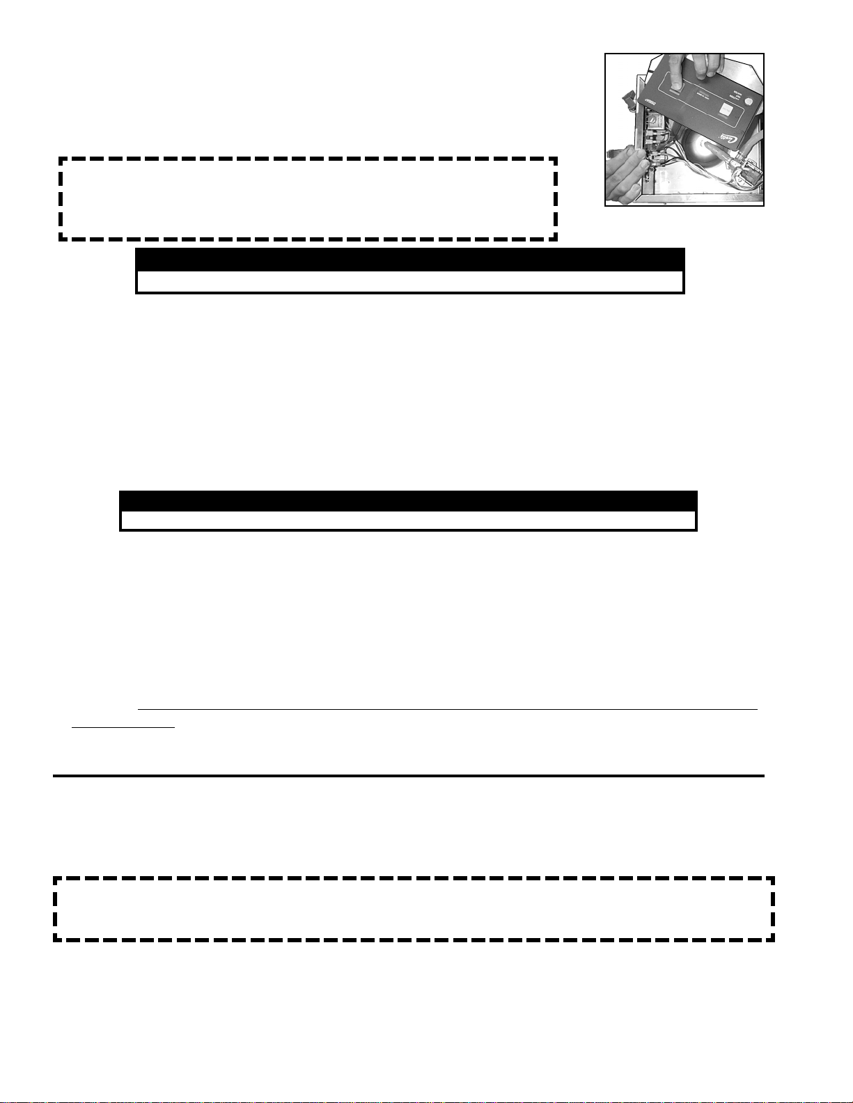
3. Unplug the ribbon connector from the control board then take the new
membrane and plug the connector into the control board. Place it on a hard
surface outside the unit.
CAUTION Do not bend the new membrane.
When pressing the buttons always have a hard, flat, surface to push
against. The tiny dome switches within the membrane may become
inverted unless you have something solid behind it.
WARNING TO HELP AVOID PERSONAL INJURY
Do not place objects or reach your hands into the open unit.
4. Return power to the unit and press the ON/OFF button on the new membrane control panel.
5. If your unit still does not function normally, your problem may not be with the membrane panel, but in
another component. If your unit runs okay, then proceed with the replacement of the membrane
control panel.
Figure 3. Testing
Membrane, Typical
1. Slide out the brew cone and clean around the sprayhead and dome using a nontoxic cleaner.
2. Remove the sprayhead from the brewer and clean it. This should be done at least once a week, more
often in heavy lime areas.
3. Wipe any spills, dust or debris from the exterior surfaces.
4. Clean the brew cone slide rails with a brush or damp cloth.
5. The outside surfaces should be cleaned with a stainless steel polish only, to prevent scratches.
6. The inside of the heating tank may occasionally require deliming. The frequency is determined by
local water conditions.
CLEANING AND PREVENTIVE MAINTENANCE
CAUTION: Do not use cleansers, bleach liquids, powders or any other substance that contains chlorine.
These products promote corrosion and will pit the stainless steel.
THE USE OF THESE PRODUCTS WILL VOID YOUR WARRANTY.
Figure4. IllustratedPartsList,MainView(Alpha3DShown).
ALPHA3D
ILLUSTRATEDPARTS
THIS FIGURE (AND FIG. 4.) SHOW THE
ALPHA 3D. ALL OTHER ALPHAS ARE
SIMILAR EXCEPT WHERE DETAILED
(SEE FIGURES 9, 10, 11, 12).
A
12
12
12
1
1
12
12
12
12
12
12
12
12
12
12
12
12
12
12
12
12
12
12
12
12
12
12
~
A
E
8
Figure5. Illustrated Parts List, DetailBubbles.
ALPHA
ILLUSTRATEDPARTS
29
123456789012345678901234567890
123456789012345678901234567890
123456789012345678901234567890
123456789012345678901234567890
123456789012345678901234567890
123456789012345678901234567890
123456789012345678901234567890
123456789012345678901234567890
123456789012345678901234567890
123456789012345678901234567890
123456789012345678901234567890
123456789012345678901234567890
123456789012345678901234567890
123456789012345678901234567890
123456789012345678901234567890
123456789012345678901234567890
123456789012345678901234567890
123456789012345678901234567890
123456789012345678901234567890
123456789012345678901234567890
123456789012345678901234567890
123456789012345678901234567890
123456789012345678901234567890
123456789012345678901234567890
123456789012345678901234567890
123456789012345678901234567890
123456789012345678901234567890
1234567
1234567
1234567
1234567
1234567
12345678
12345678
12345678
12345678
12345678
12345678
12
12
12
12
12345678
12345678
12345678
12345678
12345678
1234567
1234567
1234567
1234567
1234567
B
Figure 8. Alpha Tank.
48 57
50
49
49
47
55
54
123
1
2
3
1
2
3
1
2
3
1
2
3
1
2
3
1
2
3
1
2
3
1
2
3
1
2
3
1
2
3
1
2
3
1
2
3
1
2
3
1
2
3
1
2
3
1
2
3
1
2
3
1
2
3
1
2
3
1
2
3
1
2
3
1
2
3
1
2
3
1
2
3
1
2
3
1
2
3
1
2
3
1
2
3
1
2
3
1
2
3
1
2
3
1
2
3
1
2
3
123
12
12
12
12
12
12
12
12
12
12
12
12
12
12
12
12
12
12
12
12
12
12
12
12
12
12
12
12
12
12
12
12
12
12
12
123
123
123
123
F
F
E
4
49
43 46
48
49
52 53 54
49
50 57
42
44
55
64 58
9
10
ALPHA DIGITAL Parts List
DESCRIPTION
PART
NUMBER
INDEX
NUMBER
LABEL, "CAREFUL HOT SURFACE"
WARMER DECK, UPPER ALPHA
COVER, WARMER ALPHA
VALVE,DUMPLEFT 120V 12W
FITTINGASSEMBLYSPRAYHEADPLATED
O' RING, 1/2" I.D.
KIT, MICROPROCESSOR ASSY, ALPH-D W/BRD, HT SNK .
SCREW, 4x3/8 PHIL PAN HEAD
MEMBRANECONTROL PANELALPHA3D
INSULATION,HEATSLEEVEALPHA
WASHER, TANK LID
NUT, 6-32, HEX S.S.
SPACER, BOARD .25 DIA x .264
FAUCET, HOT WATER
SEATCUP, SILICONE
COVER, FRONT ALPHA 1D, -2D, -3D
NUT, LOCK 5/8" BRASS
SPRAYHEAD, RED (.131 DIA.)
BUSHING,5/8"SNAP-IN
BREW CONE, 7 1/8" ASSEMBLY, STAINLESS
BREW BASKET, WIRE
LEG, SCREW BUMPER, 3/8-16 STD
GRIP, CORD 7/8"
CORD, POWER 6' 14/3 BLK SJTO
ELBOW, 1/4 x 3/8, FLARE
SCREW, MACHINE, 1/4 - 20 x 1/2" PH HEAD S/S
VALVE,INLET 1GPM120V10W
COVER, BOTTOM ALPHA 3
TOGGLE SWITCH, 120V
COMPOUND, SILICONE 5 OZ.
SCREW, PAN HEAD, 8-32 x 1/4"
PLATEWARMERALPHA
WARMER ELEMENT, 90W 120V
NUT,KEP,8-32, ZINC
WARMER ASSEMBLY 90W 120V
LID,HEATINGTANK
GASKET,TANKLID
SCREW, 8-32x 1" SLOTTED HEX SS
NUT,JAM5/8" NPT BRASS
SENSOR,HEATINGTANK
FITTING,ASSEMBLYOVERFLOW
FITTING,ASSEMBLYINLET
PROBE, WATER LEVEL
SHOCK GUARD FOR HEATING ELEMENT
WC-38310
WC-6205
WC-6826
WC- 889
WC-2977
WC-4320
WC-37015
WC-4436
WC-39173
WC-3029
WC-43041
WC-4238
WC-43045
WC-1809
WC-1806
WC-5477
WC-4213
WC-2936
WC-1411
WC-3323
WC-3317
WC-3503
WC-1408
WC-1200
WC-2401
WC-4616
WC- 826L
WC-5819
WC- 102
WC-5231
WC-4426
WC-37102
WC- 947
WC-4201
WC-6234
WC-5851
WC-43062
WC-4543
WC-4211
WC-1438
WC-29015
WC-29009
WC-5502-01
WC-4394
1
2
3
4
5
6
8
9
10
11
12
13
14
15
16
17
18
19
20
22
23
24
25
26
27
28
29
30
31
32
33
35
36
37
39
42
43
44
46
47
48
49
50
52
11
ALPHA DIGITAL Parts List
DESCRIPTION
INDEX
NUMBER
53
54
55
56
57
58
59
60
61
63
64
65
WASHER, 9/16" TEFLON . . . . . . . . . . . . . . . . . . . . . . .
ELEMENT, HEATING 1.45KW 120V W/JAM NUTS & SILICONE WSHR
THERMOSTAT RST . . . . . . . . . . . . . . . . . . . . . . . . . .
PLUG, TANK DRAIN PP RED
INSULATION,WRAPALPHA-D
TUBE, SILICONE, 5/16" I.D. . . . . . . . . . . . . . . . . . . . .
KIT, INLET VALVE REPAIR USE ON WC- 826L
WASHER, FLOW .35GPM .5" . . . . . . . . . . . . . . . . . . .
SHOCK GUARD, RESET THERM . . . . . . . . . . . . . . . .
KIT, DUMP VALVE FOR WC866, WC889, WC816, WC817 & WC818
PLASTIC TEE . . . . . . . . . . . . . . . . . . . . . . . . . . . . . . . .
O' RING, 3/4" I.D. . . . . . . . . . . . . . . . . . . . . . . . . . . . .
PART
NUMBER
WC-4306
WC- 917-04
WC- 522
WC-43058
WC-3685
WC-5310
WC-3765L
WC- 829
WC-43055
WC-3763
WC-29018
WC-4320
ITEMS SPECIFIC TO ALPHA 1D, 2D, 3DR, 3DL, 5D, 6D (SEE IPB, PAGES 14, 15 & 16)
66
67
68
69
70
71
72
73
74
75
WC-6206
WC-5820
WC-6224
WC-39174
WC-39175
WC-6642
WC-6666
WC-5896
WC- 129
WC-3621
COVER, TOP ALPHA 1D, 3DR & 3DL . . . . . . . . . . . . . .
COVER, BOTTOM ALPHA 3DR & 3DL, 5DR & 5DL . . . . .
COVER, TOP ALPHA 2D . . . . . . . . . . . . . . . . . . . . . . .
MEMBRANE CONTROL PANEL ALP-2D . . . . . . . . . . . . .
MEMBRANE CONTROL PANEL ALP-1D . . . . . . . . . . . . .
COVER, TOP ALPHA 6D . . . . . . . . . . . . . . . . . . . . . . .
COVER, CENTER WRAP ALPHA 6D . . . . . . . . . . . . . . .
COVER, BOTTOM ALPHA 6D . . . . . . . . . . . . . . . . . . . .
SWITCH, WARMER RED ALPHA 5D . . . . . . . . . . . . . . .
BREWCONE, UNIVERSAL PLASTIC STD. . . . . . . . . . . . . . . . .
ALPHAEXPORTCOMPONENTS
76
77
78
79
80
81
82
WC- 103
WC- 305
WC- 701
WC- 856
WC- 860
WC- 922-04
WC-37163
TOGGLE SWITCH, 220V . . . . . . . . . . . . . . . . . . . . . . .
POWER BLOCK . . . . . . . . . . . . . . . . . . . . . . . . . . . . .
TRANSFORMER, 220V - 120V . . . . . . . . . . . . . . . . . .
VALVE, INLET 220V . . . . . . . . . . . . . . . . . . . . . . . . . .
VALVE, DUMP 220V . . . . . . . . . . . . . . . . . . . . . . . . .
ELEMENT,HEATING3.5KW 220V W/JAMNUTS,SILICONEWSHR
KIT, WARMER ELEMENT 100W 220V
12
ALPHA 3DR &
ALPHA 3DL
THISFIGUREILLUSTRATESTHEDIFFERENCES
BETWEENTHEALPHA3DR/LANDTHEALPHA
3D. THE ALPHA 3DR/L HAS A PLAIN TOP
COVERANDAWIDEBOTTOMCOVER..
Figure6.IllustratedParts,Alpha3DR&3DL.
ALPHA 3DR
ALPHA 3DL
Figure8. Illustrated Parts, Alpha1D.
ALPHA 1D
ALPHA 2D
13
THISFIGUREILLUSTRATESTHEDIFFERENCES
BETWEENTHEALPHA2DANDTHEALPHA3D.
THE ALPHA 2D HAS ONLY TWO WARMERS, A
DIFFERENTTOPCOVERANDTWOWARMER
SWITCHESONTHESWITCHPANEL.
Figure7. Illustrated Parts, Alpha2D.
1
1
1
1
1
12
1
12
12
12
THISFIGUREILLUSTRATESTHEDIFFERENCE
BETWEENTHEALPHA1DANDTHEALPHA3D.
THEALPHA 1D HASA PLAIN TOPCOVER. THE
ALPHA1DHASONLYONEWARMERANDONE
WARMERSWITCHONTHESWITCHPANEL.
12
12
12
12
12
12
1
1
12
12
12
12
12
12
1
12
12
1
1
1
1
1
1
1
1
12
12
12
12
1
12
12
12
12
12
12
1
1
12
1
1
12
1
1
12
1
1
12
12
1
12
THE ALPHA 6D IS BASICALLY
AN ALPHA 3DR AND AN ALPHA
3DLLINKEDTOGETHER.
THISFIGUREILLUSTRATESTHE
DIFFERENCESBETWEENTHE
ALPHA 6D AND THE ALPHA 3D.
THE ALPHA 6D HAS A TOTAL
OFSIXWARMERS,ALARGER
TOPCOVER,CENTERCOVER,
ANDBOTTOMCOVER.
ALPHA 6D 71
Figure9. Illustrated Parts, Alpha6D.
72
73
14
Figure10.IllustratedParts,Alpha5D.
74
ALPHA 5DL &
ALPHA 5DR
THISFIGUREILLUSTRATESTHE
DIFFERENCESBETWEENTHEALPHA5Ds
AND THE ALPHA 3D. THE ALPHA 5D HAS
TWOADDITIONALSIDEWARMERS,AS
WITH THE ALPHA 3DL & 3DR BUT WITH
TWOSEPERATEWARMERSWITCHES.
15
16
17
18
19

Other manuals for Alpha 1D

1

This manual suits for next models

7

Other Curtis Coffee Maker manuals

Curtis CAFE 1DB User manual

Curtis

Curtis CAFE 1DB User manual

Curtis GEM-120A User manual

Curtis

Curtis GEM-120A User manual

Curtis GEM-12D User manual

Curtis

Curtis GEM-12D User manual

Curtis GEMTS User manual

Curtis

Curtis GEMTS User manual

Curtis G3 GEMX IntelliFresh FreshTrac... User manual

Curtis

Curtis G3 GEMX IntelliFresh FreshTrac... User manual

Curtis G4 ThermoProX User manual

Curtis

Curtis G4 ThermoProX User manual

Curtis ALP2GT12A000 User manual

Curtis

Curtis ALP2GT12A000 User manual

Curtis CAFEPC2CS10000 User manual

Curtis

Curtis CAFEPC2CS10000 User manual

Curtis Soluble Coffee Machine User manual

Curtis

Curtis Soluble Coffee Machine User manual

Curtis CAFE PC1 User manual

Curtis

Curtis CAFE PC1 User manual

Curtis Alpha FreshTrac G3 Series User manual

Curtis

Curtis Alpha FreshTrac G3 Series User manual

Curtis CAFE 0AP User manual

Curtis

Curtis CAFE 0AP User manual

Curtis CAFEOAT3 User manual

Curtis

Curtis CAFEOAT3 User manual

Curtis Alpha G3 Configuration guide

Curtis

Curtis Alpha G3 Configuration guide

Curtis CGC User manual

Curtis

Curtis CGC User manual

Curtis GEM-612ILD Instruction Manual

Curtis

Curtis GEM-612ILD Instruction Manual

Curtis D500GTH User manual

Curtis

Curtis D500GTH User manual

Curtis GEMINI INTELLIFRESH User manual

Curtis

Curtis GEMINI INTELLIFRESH User manual

Curtis ALP3GT15A826 User manual

Curtis

Curtis ALP3GT15A826 User manual

Curtis TBS User manual

Curtis

Curtis TBS User manual

Curtis TLCG1509S User manual

Curtis

Curtis TLCG1509S User manual

Curtis ThermoPro G4 User manual

Curtis

Curtis ThermoPro G4 User manual

Curtis MWMGT User manual

Curtis

Curtis MWMGT User manual

Curtis G3 Series User manual

Curtis

Curtis G3 Series User manual

Popular Coffee Maker manuals by other brands

Siemens iQ500 TP5 Series user manual

Siemens

Siemens iQ500 TP5 Series user manual

Nespresso My Machine Vertuo Plus manual

Nespresso

Nespresso My Machine Vertuo Plus manual

Keurig My K-Cup 2.0 instructions

Keurig

Keurig My K-Cup 2.0 instructions

Bosch TCA64 SERIES operating instructions

Bosch

Bosch TCA64 SERIES operating instructions

Limee CM01 instructions

Limee

Limee CM01 instructions

DeLonghi EC860 manual

DeLonghi

DeLonghi EC860 manual

Vitek VT-1503 Manual instruction

Vitek

Vitek VT-1503 Manual instruction

Electrolux FRESH AROMA EKAM300 Instruction book

Electrolux

Electrolux FRESH AROMA EKAM300 Instruction book

Scarlett SC-030 instruction manual

Scarlett

Scarlett SC-030 instruction manual

AEG CF 300 operating instructions

AEG

AEG CF 300 operating instructions

Saeco INTELLIA EVO HD8752 instructions

Saeco

Saeco INTELLIA EVO HD8752 instructions

Nespresso krups citiz&milk user manual

Nespresso

Nespresso krups citiz&milk user manual

SOLIS GRIND & INFUSE PERFETTA quick start guide

SOLIS

SOLIS GRIND & INFUSE PERFETTA quick start guide

Nespresso GEMINI CS 200 PRO user manual

Nespresso

Nespresso GEMINI CS 200 PRO user manual

Electrolux EKF3330 Instruction book

Electrolux

Electrolux EKF3330 Instruction book

BRAVILOR BONAMAT Solo Operator's manual

BRAVILOR BONAMAT

BRAVILOR BONAMAT Solo Operator's manual

Cuisinart CPO-850 Instruction

Cuisinart

Cuisinart CPO-850 Instruction

Bosch TASSIMO happy TAS1009 instruction manual

Bosch

Bosch TASSIMO happy TAS1009 instruction manual

manuals.online logo
manuals.online logoBrands
  • About & Mission
  • Contact us
  • Privacy Policy
  • Terms and Conditions

Copyright 2025 Manuals.Online. All Rights Reserved.