1
This Curtis Gold Cup Unit is Factory Pre-Set and Ready to Go Right from the Box.
Following are the Factory Settings for your Coffee Brewing System:
•BrewTemperature=200°F
•BrewVolume=SettoVesselRequirement.
SystemRequirements:
•WaterSource20–90PSI(MinimumFlowRateof½GPM)
•Electrical:Seeattachedschematicforstandardmodelorvisitwww.wilburcurtis.com
for your model.
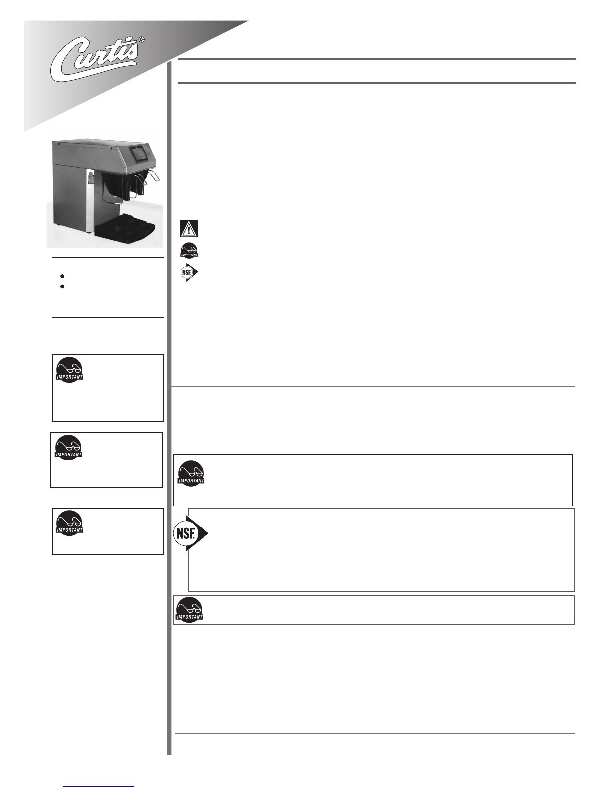
Models
CGC
CGC1
CAUTION: DO NOT
connect this brewer to hot
water. The inlet valve is
not rated for hot water.
CAUTION: Please use
this setup procedure
before attempting to use
this brewer. Failure to follow the
instructions can result in injury or the
voiding of the warranty.
IMPORTANT: Equipment
to be installed to comply
with applicable govern-
mental plumbing/electrical codes
having jurisdiction.
ISO 9001:2008 REGISTERED
WILBUR CURTIS CO., INC.
6913 West Acco Street
Montebello, CA 90640-5403
For the latest information go to
www.wilburcurtis.com
Tel: 800-421-6150
Fax: 323-837-2410 For the latest specications and information go to www.wilburcurtis.com
Thisequipmentisdesignedforcommercialuse.Anyservicingotherthancleaningand
routinemaintenanceshouldbeperformedbyanauthorizedWilburCurtisCompanySer-
viceTechnician.
• DONOTimmersetheunitinwateroranyotherliquid
• Toreducetheriskofreorelectricshock,DONOTopenservicepanels. There
arenouserserviceablepartsinside.
• Keephandsandotheritemsawayfromhotareasoftheunitduringoperation.
• Nevercleanwithscouringpowdersorharshchemicals.
Important Safeguards/Symbols
Service Manual – Curtis Gold Cup
Wilbur Curtis Co., inC.
Symbols:
WARNINGS – To help avoid personal injury
Important Notes/Cautions – from the factory
Sanitation Requirements
NSF International requires the following water connection:
1. A quick disconnect or additional coiled tubing (at least 2x the depth of the unit) is required so
that the unit can be moved for cleaning.
2. This unit must be installed with adequate backow protection to comply with applicable federal,
state and local codes.
3. Water pipe connections and xtures directly connected to a potable water supply shall be sized,
installed and maintained in accordance with federal, state, and local codes.
3. Connect the unit to electrical circuit with appropriate amperage rating; refer to serial tag on the machine and
local/national electrical codes to determine circuit requirements.
4. Once power has been supplied to the unit, ip the toggle switch to the ‘ON’ position (located on the rear of
the unit), the water tank will begin to ll. When the water level in the tank reaches the probe, the heating
element(s) will turn on.
5. Water in the heating tank will require approximately a half hour before reaching operating temperature (factory
setting of 200°F). Where applicable, turn on the Universal Control Module (UCM). When the unit reaches
operating temperature, it will display “READY TO BREW”.
NOTE: A water ltration system must be used to help maintain trouble-free operation. Air must be
purged from the cartridge prior to connection to equipment. In areas with extremely hard wa-
ter, we highly recommend the use of a Curtis approved water lter. For our full line of lters, please
log on to www.wilburcurtis.com.
SETUP STEPS
1. The unit should be level (left to right - front to back), on a secure surface.
2. Connect the water line to the water inlet tting on the rear of the unit. Water volume ow to the machine
should be consistent. Use tubing sized sufciently to provide a minimum ow rate of one gallon per minute.
NOTE: Electrical source should have a minimum 30A internal common trip circuit breaker between
the brewer and the main supply, which breaks all poles with a contact separation of at least 3 mm.


