Curtis 1352 User manual

Manual
Model 1352
eXm Expansion Module
Read Instructions Carefully!
Specications are subject to change without notice.
© 2015 Curtis Instruments, Inc. ® Curtis is a registered trademark of Curtis Instruments, Inc.
© The design and appearance of the products depicted herein are the copyright of Curtis Instruments, Inc. 38442, Rev D 10/16
Curtis Instruments, Inc.
200 Kisco Avenue
Mt. Kisco, NY 10549
www.curtisinstruments.com

Curtis 1352 eXm Manual, R e v. D ii
CONTENTS
1. OVERVIEW ..............................................................................1
2. INSTALLATION AND WIRING.............................................4
Mounting the Module .........................................................4
Connections and Wiring Guidelines....................................6
Wiring: Basic Configuration ...............................................8
Input/Output Specifications...............................................10
3. CANopen COMMUNICATIONS .........................................13
Minimum State Machine ...................................................13
NMT Messages .................................................................15
Emergency Messages .........................................................16
Heartbeat ..........................................................................16
4 PDO COMMUNICATIONS .................................................17
5. SDO COMMUNICATIONS..................................................19
SDO Master Request, SDO-RX (MOSI) .........................19
SDO eXm Response, SDO-TX (MISO) ...........................20
Types of SDO Objects ......................................................20
Communication Profile Objects ........................................21
Device Parameter Objects .................................................26
Device Monitor Objects ....................................................30
6. DIAGNOSTICS AND TROUBLESHOOTING....................31
Troubleshooting .................................................................31
Fault Log............................................................................33
appendix aVehicle Design Considerations
appendix bSpecifications, 1352 eXm Module

iii Curtis 1352 eXm Manual, R e v. D
FIGURES
fig.1: Curtis 1352 eXm module......................................................... 1
fig.2: Mounting dimensions, Curtis 1352 eXm module ................... 4
fig.3: Basic wiring diagram................................................................ 8
TABLES
table 1: Connector pinout................................................................... 7
table 2: Communication profile objects ............................................ 21
table 3: Device parameter objects...................................................... 26
table 4: Device monitor objects......................................................... 30
table 5: Troubleshooting chart........................................................... 32
table B-1: Specifications, Curtis 1352 eXm module ............................. 36

Curtis 1352 eXm Manual, R e v. D 1
OVERVIEW
The Curtis 1352 eXm expansion module provides a simple, flexible, and low-
cost method for adding additional and specialized I/O to a system. The eXm
utilizes the popular CANopen communication bus for all control, status, and
setup. This allows many CANopen-compatible modules—from Curtis or from
third-party vendors—to be interconnected and share I/O throughout a system.
Several eXm modules can be connected to a single CAN bus to provide a wide
range of I/O. Because of its small size and tight seal, the eXm module can be
mounted remotely near the system to be controlled, thus minimizing wiring
and improving EMC.
The eXm is part of a distributed I/O system with a master controller
coordinating the CAN communications. Curtis VCL-enabled controllers such
as the 1232/34/36/39 E/SE, 1298, and 1310 can provide this master control
using custom software developed with Curtis VCL (Vehicle Control Language).
Any CANopen master can be programmed to control the eXm.
1
1 — OVERVIEW
Fig. 1 Curtis 1352 eXm
expansion module.
The Curtis 1352 eXm expansion module is ideal for material handling,
floor cleaning, aerial platforms, and other electric vehicles as well as stationary
control systems utilizing the CANopen bus. Features include:
39 multi-purpose I/O pins in a compact low cost module
36 high-frequency PWM outputs rated at 3 amps each
3Closed loop current, constant voltage, or direct PWM control on each
output
3Each output can also be used as an active high digital input
3Built-in programmable dither for hydraulic valves
More Features +

2Curtis 1352 eXm Manual, R e v. D
33 analog inputs (0–30V)
33 virtual digital inputs with programmable thresholds (using the analog
inputs)
32 analog inputs are selectable for voltage input or resistive sensors
3Built-in coil flyback diodes
3Software and hardware watchdog circuits ensure proper software operation
3CANopen interface
3Controlled by a fixed PDO map and programmable over SDOs
3IP65-rated enclosure allows the eXm to be mounted in multiple
orientations, and protects it even in harsh environments
3Status LEDs provide external status of module.
DESCRIPTIONS OF KEY FEATURES
Versatile I/O
High frequency PWM outputs
Six identical FET drivers are designed to sink up to 3 amps through a resistive
or inductive load. High frequency PWM (>16kHz) provides smooth current
to the load. Internal flyback diodes to B+ are incorporated to reduce voltage
spikes caused when pulsing coils.
Constant current and constant voltage output modes
The eXm’s DSP runs at 32 MIPS (Million Instructions per Second), allowing
the eXm to run six fast PI (Proportional/Integral) closed loop controllers. The
eXm’s PI controllers provide an accurate constant current to the load, which is
important for precise control of proportional valves.
Each output can also be programmed for constant voltage mode. In this
mode, the battery voltage is monitored and the PWM command is corrected
to provide a constant average voltage, compensating for fluctuating battery
levels and droops.
Each output can also be set to provide a directly commanded PWM%
or turned off to be used as an input.
Programmable dither for hydraulic valves
The eXm can add a programmable level of dither to the PWM output. This
keeps the seals of a proportional valve oiled, allowing the valve to move freely for
accurate PV control. Dither is only active on drivers in Constant Current mode.
1 — OVERVIEW

Curtis 1352 eXm Manual, R e v. D 3
Output as an Active High digital input
Each output can be also be used as a digital input. Each input is digitally filtered
to eliminate switch “bounce” or noise in the signal. The eXm has internal resistor
pull-downs to B– to provide active high to B+ inputs (standard Curtis input
format). The inputs utilize Schmidt Trigger logic to provide signal hysteresis,
further improving noise immunity and reducing faulty readings.
Analog inputs
The eXm has three analog inputs that are scaled to read 0–30 volts. The analog
channels are read 1000 times/second by a 12-bit ADC, resulting in a resolution
of about 0.7 millivolts. Independently adjustable filters ensure a smooth signal.
RTD/resistive sensor inputs
Analog Inputs 1 and 2 can be used with resistive sensors, such as RTDs (Resistive
Temperature Devices).
Virtual Digital Inputs
The three analog inputs are also sensed and decoded as if they were digital inputs.
A unique feature of these digital inputs is that the active high/low thresholds are
completely programmable. Thus, these inputs can be used with analog sensors
to detect conditions like over/under pressure, high/low level points, etc.
CANopen Convenience
The eXm is CANopen compliant, responding to the standard NMT, PDO, and
SDO communications as well as the CANopen DS301-required identity and
standard objects. The Curtis CANopen extensions allow additional features,
such as OEM and User default configurations and time-stamped fault logging.
The eXm will receive* a single PDO and respond* with a single PDO.
Simplifying the VCL interface to the module, the PDO-RX (MOSI) mapping is
fixed while the PDO-TX (MISO) allows several fixed mapping setups.The PDO-
TX (MISO) can be set to cyclic or event driven. All programmable parameters
and viewable values within the eXm are accessible by standard SDO transfer.
The eXm provides CANopen safety and security features, such as
Heartbeat and Error Message. A time period watchdog will shut down the
drivers if new PDOs are not received in proper cyclic timing.
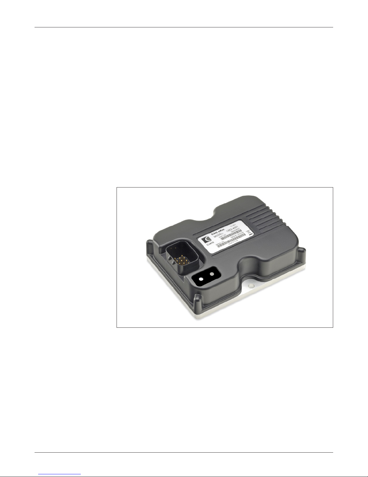
Familiarity with your Curtis eXm module will help you install and operate it
properly. We encourage you to read this manual carefully. If you have questions,
please contact the Curtis office nearest you.
* NOTE: MOSI (Master Out Slave In) = RX (Server to Client)
MISO (Master In Slave Out) = TX (Client to Server)
1 — OVERVIEW

4Curtis 1352 eXm Manual, R e v. D
2 — INSTALLATION & WIRING
2
Fig. 2 Mounting
dimensions, Curtis 1352
eXm module.
Dimensions in millimeters (and inches)
INSTALLATION AND WIRING
MOUNTING THE MODULE
The outline and mounting hole dimensions for the 1352 eXm module are shown
in Figure 2. The module should be mounted using two #10 or M5 screws.
Care should be taken to prevent contaminating the connector area
before the mating 14-pin connector is installed. Once the system is plugged
together, the eXm meets the IP65 requirements for environmental protection
against dust and water. Nevertheless, in order to prevent external corrosion
and leakage paths from developing, the mounting location should be carefully
chosen to keep the module as clean and dry as possible.
If the outputs will be used at or near their maximum ratings, it is rec-
ommended that the module be mounted to a good heatsinking surface, such
as an aluminum plate.
65 (2.6)
130 (5.2)
Status
LEDs
100
(3.9)
87
(3.4)
6.3 (0.25) dia.,
2 plcs
39
(1.5)
+
CAUTION

Curtis 1352 eXm Manual, R e v. D 5
You will need to take steps during the design and development of your
end product to ensure that its EMC performance complies with applicable
regulations; suggestions are presented in Appendix A.
The 1352 eXm contains ESD-sensitive components. Use appropriate
precautions in connecting, disconnecting, and handling the module. See instal-
lation suggestions in Appendix A for protecting the module from ESD damage.
2 — INSTALLATION & WIRING
Working on electrical systems is potentially dangerous. You should
protect yourself against uncontrolled operation, high current arcs, and
outgassing from lead acid batteries:
UNCONTROLLED OPERATION — Some conditions could cause the motor to
run out of control. Disconnect the motor or jack up the vehicle and get
the drive wheels off the ground before attempting any work on the motor
control circuitry.
HIGH CURRENT ARCS — Batteries can supply very high power, and arcing can
occur if they are short circuited. Always open the battery circuit before
working on the motor control circuit. Wear safety glasses, and use properly
insulated tools to prevent shorts.
LEAD ACID BATTERIES — Charging or discharging generates hydrogen gas, which
can build up in and around the batteries. Follow the battery manufacturer’s
safety recommendations. Wear safety glasses.
+
CAUTION

6Curtis 1352 eXm Manual, R e v. D
CONNECTIONS
All connections are made through the 14-pin AMPSEAL connector.The mating
plug housing is AMP p/n 776273-1, and the gold-plated socket terminals are
AMP p/n 770520-3 (Strip form) and 770854-3 (loose piece).The connector will
accept 20 to 16 AWG wire with a 1.7 to 2.7mm diameter thin-wall insulation.
Note that the eXm pins are not sealed until the mating connector is
fully engaged and locked. The cable harness connector has a silicone rubber
seal that is an integral part of the module’s sealing.
The 14 individual pins are characterized in Table 1.
2 — INSTALLATION & WIRING: Low Current Connections
Wiring recommendations
Power and ground (Pins 1–3)
The B+ and B– cables should be run close to each other between the module
and the battery. For best noise immunity the cables should not run across the
center section of the module.To prevent overheating these pins, the wire gauge
must be sufficient to carry the continuous and maximum loads that will be
seen at each pin.
PWM drivers (Pins 9–14)
The PWM drivers produce high frequency (16kHz) pulse waves that can radiate
RFI noise. The wire from the module to the load should be kept short and
routed with the return wire back to the module.
CAN bus (Pins 4 and 5)
It is recommended that the CAN wires be run as a twisted pair. However,
many successful applications at 125 kBaud are run without twisting, simply
using two lines bundled in with the rest of the low current wiring. CAN wiring
should be kept away from the high current cables and cross it at right angles
when necessary. If the eXm is at the end of the CAN bus, the bus needs to be
terminated by externally wiring a 120Ω½W resistor across CAN High and
CAN Low.
All other low current wiring (Pins 6–8)
The remaining low current wiring should be run according to standard
practices. Running low current wiring next to the high current wiring should
always be avoided.
51
1410
6 9
+
CAUTION

Curtis 1352 eXm Manual, R e v. D 7
2 — INSTALLATION & WIRING: Low Current Connections
Table 1 Connector Pinout
pin name description
1 B–Ground; connected to battery B– terminal.
2 B– Redundant ground, for high-current applications.
If the combined draws from the driver pins could exceed
9A, both B– pins must be connected to the battery’s B–
terminal
3 B+ Power; connected to the battery’s B+ terminal.
4 CAN L CAN bus Low communication line.
5 CAN H CAN bus High communication line.
6 Analog Input 1 Voltage or resistive input.
7 Analog Input 2 Voltage or resistive input.
8 Analog Input 3 Voltage input only.
9 Input/Output 5 Active High input & high-power PWM active Low output.
10 Input/Output 6 Active High input & high-power PWM active Low output.
11 Input/Output 1 Active High input & high-power PWM active Low output.
12 Input/Output 2 Active High input & high-power PWM active Low output.
13 Input/Output 3 Active High input & high-power PWM active Low output.
14 Input/Output 4 Active High input & high-power PWM active Low output.

8Curtis 1352 eXm Manual, R e v. D
Fig. 3 Basic wiring diagram, Curtis 1352 eXm module.
2 — INSTALLATION & WIRING: Standard Wiring Diagram
WIRING: BASIC CONFIGURATION
A basic wiring diagram is shown in Figure 2, and described below. The diagram
shows shows the standard power and battery connections, as well as a variety
of basic uses for the inputs and outputs.
Power Connection
The battery is connected to the module’s B+ pin though a fuse, an optional
diode, and a keyswitch. The fuse protects the wiring in the event of a short or
failure. The return path of the coils is also brought back to the B+ pin to utilize
the flyback diodes connected inside the eXm between B+ and each driver output.
The keyswitch is used to turn on the system. When the keyswitch is closed,
B+ goes high and the eXm’s power supply brings up the module.
Outputs
All the drivers (Pins 9–14) are identical. Each is capable of driving a closed-loop
current-controlled proportional valve or a voltage-controlled contactor. Each
driver has independent mode, max, and dither settings.
Pin 5
Pin 4
Pin 2
Pin 1
Pin 3
Pin 11
Pin 12
Pin 13
Pin 14
Pin 9
Pin 10
Pin 6
Pin 7
Pin 8

Curtis 1352 eXm Manual, R e v. D 9
These are high-power drivers.The internal impedance to ground will cause
leakage current to flow through the output even when the output driver is off.
This leakage current can be enough (>2 mA) to light high-efficiency LEDs.
In the wiring diagram, the output at Pin 11 is shown driving a propor-
tional valve coil. This driver is programmed for Constant Current mode and
would have some Dither applied.
The second output shown (Pin 12) is driving a basic contactor coil. This
output is in the Constant Voltage mode and can be set to run at a lower voltage
than the nominal battery voltage.
Switch Inputs
All the outputs can be used as Active High inputs (“On” when connected to
B+). It is important that the output command be set to 0% for each input used
or a direct short from B+ to B– will be generated when the driver is pulsed On,
which could damage the FET driver. In the wiring diagram, I/O 6 is shown as
an Active High input switching to B+.
Analog Inputs
The first analog input is shown being used with an RTD. This requires enabling
the Analog Input 1 pull-up, which allows the input to measure resistive sensors.
Note that Analog Input 3 can only be used with sensors that provide a voltage
output.
CAN Bus
The eXm has an internal 1kΩbus termination resistor. This internal impedance
matches the system requirements for a mid-line connection or short stub
connection. If the eXm is to be used at the end of the CAN bus, an external
120Ω½W resistor must be added externally across the CAN H and CAN L
lines at or near the eXm to provide proper termination. The higher the bit
rate (i.e., the higher the baud), the more critical this becomes. The eXm can
communicate up to 1Mbps on a properly terminated/wired bus.
2 — INSTALLATION & WIRING: Standard Wiring Diagram

Curtis 1352 eXm Manual, R e v. D 10
INPUT/OUTPUT SIGNAL SPECIFICATIONS
The input/output signals wired to the 14-pin connector can be grouped by
type as follows; their electrical characteristics are discussed below.
— digital inputs
— digital outputs
— analog inputs with virtual digital input
— power
— communication lines.
Digital inputs
The six digital I/O lines can be used as digital (on/off) inputs. Normal “on”
connection is direct to B+; “off” is direct to B–. Input will pull low (off) if no
connection is made.
2 — INSTALLATION & WIRING: I/O Signal Specications
Because these six lines can also be used as driver outputs, it is important
to ensure that Output Driver Mode is set appropriately for each line. For each
pin that will be used as a digital input, Output Driver Mode must be set to
Input Only (see page 26). Otherwise, a direct short from the battery through
the internal driver FET will occur when the input is switched high and the
FET is turned on.
Digital outputs
The six digital I/O lines can also be used as outputs. They can be either digital
(on/off) or Pulse Width Modulated (PWM) outputs. Each driver is active low,
meaning the output will pull low (to B–) when On. The PWM is at a fixed
frequency (16 kHz), and can vary duty cycle from 0 to 100%.
DIGITAL INPUT SPECIFICATIONS
logic input protected esd
signal name pin thresholds*impedance*voltage range tolerance
Input/Output 1 11 All models: 12–36V models: 12–36V models: All models:
Input/Output 2 12 Low = 2.8 V about 10 kΩ-0.5 to 50 V ±8 kV (air
Input/Output 3 13 High = 6.3 V 36–80V models: 36–80V models: discharge)
Input/Output 4 14 about 47 kΩ-0.5 to 105 V
Input/Output 5 9
Input/Output 6 10
*Tolerance ±5%.
DIGITAL OUTPUT SPECIFICATIONS
pwm & output protected esd
signal name pin frequency current*voltage range tolerance
Input/Output 1 11 All models: All models: 12–36V models: All models:
Input/Output 2 12 0–100%
Sink 3 A -0.5 to 50 V ±8 kV (air
Input/Output 3 13 duty cycle 36–80V models: discharge)
Input/Output 4 14 at 16 kHz -0.5 to 105 V
Input/Output 5 9
Input/Output 6 10
*Tolerance ±5%.
51
1410
6 9
51
1410
6 9

11 Curtis 1352 eXm Manual, R e v. D
The drivers can be set for Constant Current, Constant Voltage, or Direct
PWM control mode.
In Constant Current mode, the driver command of 0 to 100%
is interpreted as a current from 0 to Max Output setting (up
to 3 amps). Internal current shunts are measured and fed back
to a closed loop PI controller to provide a steady current over
changing loads and supply voltages.
In Constant Voltage mode, the driver command of 0 to 100%
is interpreted as a voltage from 0 to Max Output (up to 80
volts). The battery voltage is constantly monitored and fed
back to a closed loop PI controller to provide a steady volt-
age, compensating for battery droop and discharge. If the
command is higher than the driver can output, the PWM
will max out at 100%.
In Direct PWM mode, the driver command of 0 to 100% is
directly output on the driver.
Each driver is monitored and will detect a short in the load, a failed internal
driver FET, and/or an open in the load wiring. At near 0% and 100% PWM,
it is not possible to discern each fault and some faults will not be detected.
If the driver outputs are connected to inductive loads, the coil should
have a return line to the B+ pin of the eXm. This connection provides a path
for the internal freewheel diodes to clamp the turn-off spike. Failure to make
this connection with inductive loads can cause permanent damage to the eXm
module as well as propagate failures of other electronics in the system due
to the high voltage spike caused when an inductive load turns off without a
freewheel path.
Analog inputs
The three analog inputs can easily be configured for use with potentiometers,
pressure sensors, temperature sensors, and resistive sensors (like RTDs). Each
input is read 1000 times per second by a 12-bit ADC and filtered to provide
a clean signal. The voltage reading is returned over the PDO in hundredths
of a volt, so 30 volts at an analog input will be read back over the PDO-TX
(MISO) as 3000.
2 — INSTALLATION & WIRING: I/O Signal Specications
ANALOG INPUT SPECIFICATIONS
operating input protected esd
signal name pin voltage impedance*voltage range tolerance
Analog Input 1 6 0 to 30 V 20 kΩ; - 1 V to B+ ± 8 kV (air
Analog Input 2 7 10 kΩwith discharge)
Analog Input 3 8 pull-up enabled
*Tolerance ±5%.
Analog Inputs 1 and 2 have a pull-up resistor that can be programmed to
provide a low voltage at the input. This allows the ADC to read resistive values,
51
1410
6 9

Curtis 1352 eXm Manual, R e v. D 12
2 — INSTALLATION & WIRING: I/O Signal Specications
as the external resistance to ground will provide a divider with the internal pull-
up. The pull-up is 10 kΩto ≈ 4.4 volts. The pull-up is turned on by setting the
correct bit in the Analog Source Enable parameter. The eXm will send back a
reading of the external resistance in ohms. The maximum resistance that can
be measured is 6.5 kΩ. An open pin will read 65535 (FFFFh).
These analog inputs can also be used simultaneously as virtual digital
inputs. These virtual digital inputs are created by comparing the filtered ana-
log signal to the the High and Low Threshold parameters. These parameters
also provide hysteresis. Once the signal goes above the High Threshold and is
sensed as On, it must pass below the Low Threshold to be be considered Off;
simply going below the High Threshold is not enough. The same is true for
a Low to High transition. Note that the thresholds are always set in voltage;
therefore if the Analog Source Enable (pull-up) is set to On for any channel,
the thresholds must be below 4.4 V in order to be active.
Power
The power pins are each capable of carrying up to 9A when using 16 AWG wire.
Every application must use B+ (pin 3) and at least one of the B– connections
(pins 1 and 2).
Since the eXm’s six drivers can sink a maximum combined load of 18 A,
you will need to determine the application’s maximum total loading on B–. To
prevent the pin from overheating, the proper wire gauge must be used* and, if
the load is greater than 9 amps, both B– pin connections are required.
If it is determined that both B– pins are required, you must also deter-
mine the load on B+. This requires either knowledge of the expected PWM or
actual in-application measurements.The combined average current recirculating
through the B+ pin cannot exceed 9 amps. This can be an issue if the inductive
loads are specified at a lower voltage than the battery supply as the applied
PWM would normally be reduced to not exceed the average applied voltage or
current. The lower PWM in turn raises the average current flowing through the
B+ pin as the load current recirculates for a great portion of the PWM period.
* 18 AWG is limited to 7.3 Amps. 20 AWG is limited to 6.6 Amps.
Communications lines
Pins 4 and 5 provide the CAN connections.
CAN SIGNAL SPECIFICATIONS
supported protected esd
signal name pin protocol/devices data rate voltage range tolerance
CANH 5 CANopen up to 1 Mbps Continuous= ± 8 kV (air
CANL 4 - 36 V to discharge)
(MaxV + 10 V)
Transient=
± 200 V
51
1410
6 9
51
1410
6 9

Curtis 1352 eXm Manual, R e v. D 13
3 — CANopen COMMUNICATIONS
3CANopen COMMUNICATIONS
The eXm adheres to the industry standard CANopen communication protocol
and thus will easily connect into many CAN systems, including those using
the Curtis AC and Vehicle System controllers (1234/36/38, 1298, and 1310).
Any CANopen-compatible master can be programmed to control the eXm.
The eXm’s PDOs are fixed (see section 4). There is one incoming PDO-
RX (MOSI) for the driver commands and one response PDO-TX (MISO) for
the input status. Expedited SDOs (see section 5) are used to access all eXm
parameters and allow monitoring of non-runtime variables and flags.
The time between incoming PDOs is monitored and if excessive, will
flag a fault. This allows the eXm to know that the system is still under master
control. The eXm will also produce a cyclic heartbeat message, which is the
CiA-preferred method of slave node error control.
Emergency messages are sent sporadically whenever an error status flag
within the eXm changes state.
MINIMUM STATE MACHINE
The eXm will run the CANopen minimum state machine as defined by CiA.
The CANopen minimum state machine has four defined states: Initialization,
Pre-Operational, Operational, and Stopped.
When the eXm powers up, it goes to the Initialization state; this is also
known as the Boot-up state. No CAN communications from the eXm are
transmitted in this state although the eXm listens to the CAN bus. When the
eXm has completed its startup and self-tests, it issues an initialization heartbeat
message and automatically goes to the Pre-Operational state.
In the Pre-Operational state, the eXm can receive and respond to SDOs
and NMT commands, and will send its heartbeat. It will not receive or send
Transmit Boot-up
Initialization
Pre-Operational
Operational
Stopped
Power-On
Reset
Reset
Module
Reset
Communication

14 Curtis 1352 eXm Manual, R e v. D
PDOs. When the master issues a goto Operational State NMT command, the
eXm will go to full normal operation.
In the Operational state, the eXm will start receiving and responding to
PDOs and process all other necessary CANopen messages.
If the master sends a Stop NMT command or the eXm detects an inter-
nal fault, the eXm will go to the Stopped state. In the Stopped state the eXm
will listen for NMTs and produce its heartbeat message only. PDOs and SDOs
(including any timeouts) are ignored.
At any point, if the master sends a Reset Communication or Reset Mod-
ule (warm boot), the eXm will go to the Initialization state as if there were a
power-cycle.
Baud Rates
The eXm will run at one of five selectable baud rates: 125k, 250k, 500k, 800k,
and 1M. Rates below 125k are not supported.
The baud rate can be changed by an SDO. Changes in the baud rate
require an NMT rest or key-cycle to make the new rate active.
Node Addresses
The node address of the eXm can be 1 to 127 and is used by CANopen to route
messages to the eXm and to denote messages from the eXm. The node address
is part of the COB-ID and therefore also plays a part in message priority and
bus arbitration.
Changes to the node address require an NMT reset or power-cycle.
Standard Message Identiers
The eXm will produce—and respond to—the standard message types with the
following CANopen identifiers.
Message Type Message Identier
NMT 0000 – 00hXx
EMERGENCY 0001 – 01hXx
PDO-TX (MISO) 0011 – 03hXx
PDO-RX (MOSI) 0100 – 04hXx
SDO-TX (MISO) 1011 – 0BhXx
SDO-RX (MOSI) 1100 – 0ChXx
HEARTBEAT 1110 – 0EhXx
The 11-bit identification field is a fixed part of the CANopen specification
called the Communication OBject IDentification (COB-ID). This field is used
for arbitration on the bus. The COB-ID with the lowest value gets priority and
wins arbitration. Consequently, NMT messages have the highest priority of the
standard message types, and the heartbeat has the lowest priority.
3 — CANopen COMMUNICATIONS

Curtis 1352 eXm Manual, R e v. D 15
3 — CANopen COMMUNICATIONS
The standard organization of the COB-ID puts the message type in the
upper four bits, and the Node ID in the bottom seven bits:
11 10 9 8 7 6 5 4 3 2 1
Message Type Node ID
NMT MESSAGES
NMT (Network Management Transmission) messages are the highest priority
message available. The NMT message puts the eXm into one of the four defined
states. These messages have 1 byte of data sent by the master; the slave does not
respond with any data to an NMT. The eXm state value is transmitted with
each heartbeat message.
Value State
00h Initialization (or “boot-up”)
04h StoppedXx
05h OperationalXx
7Fh Pre-OperationalXx
The NMT message identifier consists of the standard message type (NMT)
in the top four bits; the bottom seven bits must be set to zero.
The first data byte of the NMT command is the command specifier:
Value Command Specier
01h Enter the Operational state
02h Enter the Stopped stateXx
80h Enter the Pre-Operational statex
81h Reset the eXm (warm boot)Xx
82h Reset the CAN busXx
The second byte of the NMT command defines whether this NMT is for
all slaves on the bus (data byte = 00h) or for a specific node (data byte = Node
ID of the eXm)

16 Curtis 1352 eXm Manual, R e v. D
EMERGENCY MESSAGES
Emergency messages are the second highest priority in CANopen and the
highest priority that a slave (like the eXm) can transmit. These messages are
sent sporadically whenever there is a change of state in the eXm’s fault flags.
An Emergency Message consists of 8 data bytes.
To prevent fast-changing fault bits from flooding the bus, a minimum
time between messages can be programmed.
Data bytes 1 and 2 define the error category. The eXm will use the device-
specific category (FFXXh) per DS301. Therefore the upper byte is FFh when
a fault is present, and the lower byte is equal to the Curtis fault code. When
no faults are present and/or the last fault has just been cleared, the emergency
message will use the error code value of 0000h.
Data byte 3 is the CANopen-required error register. Curtis products define
this as 01h if there is a fault present and 00h when all faults are clear.
Data bytes 4 through 8 define the specific fault. The eXm will place the
current 16-bit hourmeter (Object 3140h) into data bytes 4 and 5, with the MSB
in byte 5. Note that bytes 6, 7, and 8 are not used by the eXm and are always
000000h. See Diagnostics (section 6) for more detail.
Emergency Message Format indicating an error:
Emergency Message Format indicating all error(s) cleared:
HEARTBEAT
The heartbeat message is a very low priority message, periodically sent by each
slave device on the bus. The heartbeat message has a single byte of data and
requires no response. Once the eXm is in the Pre-Operational state, the next
heartbeat will be issued and will continue until communication is stopped.
The heartbeat message has only one data byte. The top bit is reserved and
should be set to zero. The bottom 7 bits hold the current NMT device state as
defined previously.
byte 1 byte 8
byte 1 byte 8
Error Category Hourmeter
FFh
Curtis
Code 01h Object 3140h 000000h
0000h 00h Object 3140h 000000h
3 — CANopen COMMUNICATIONS

Curtis 1352 eXm Manual, R e v. D 17
PDO COMMUNICATIONS
The Curtis eXm is easily controlled and monitored through two fixed
communication packets. Each data packet contains 8 bytes. One is received by
the eXm from another module (usually the system master) and in response, the
eXm sends out its packet of data. CANopen calls these packets Process Data
Objects (PDOs). PDO messages have a medium priority.
The PDO communication packets conserve bus bandwidth by bundling
the values of a group of objects into a single message. The content of these
PDOs is fixed, thus simplifying the interface.
The Curtis CANopen implementation requires that the incoming PDO-
RX (MOSI) be responded to by an outgoing PDO TX (MISO). The eXm will
respond to the PDO-RX (MOSI) with its PDO-TX (MISO) within 4 ms.
The eXm normally requires that the PDO-RX (MOSI) be cyclic from the
master. The cycle time must be less than the programmed PDO Timeout. If the
PDO-RX (MOSI) is not received within the programmed time, the eXm will
flag a fault and the eXm will disable all output drivers. If the PDO Timeout
parameter is set to 0, the timeout fault is disabled and the eXm will respond to
any PDO incoming at any rate without faulting. Take care using this setting as
the last PDO commands will stay on the eXm indefinitely.
The 1352's PDO-TX (MISO) can also be set to cyclical transmission every
4ms to 1000ms rate as soon as the eXm put in Operational Mode. Finally, the
PDO-TX (MISO) can be set to one of 5 types. Each type sends a different set
of internal data. Type 0 is the present default.
PDO-RX (MOSI) (received from the system master)
Byte 1 Byte 2 Byte 3 Byte 4 Byte 5 Byte 6 Byte 7 Byte 8
Output 1
Command
Output 2
Command
Output 3
Command
Output 4
Command
Output 5
Command
Output 6
Command Not Used Not Used
PDO-TX (MISO): Type 0
Byte 1 Byte 2* Byte 3 Byte 4 Byte 5 Byte 6 Byte 7 Byte 8
Inputs 1-6
Status
Virtual
Inputs
(lower 3
bits)
Analog
Input 1
Low Byte
Analog
Input 1
High Byte
Analog
Input 2
Low Byte
Analog
Input 2
High Byte
Analog
Input 3
Low Byte
Analog
Input 3
High Byte
PDO-TX (MISO): Type 1 Driver PWM
Byte 1 Byte 2* Byte 3 Byte 4 Byte 5 Byte 6 Byte 7 Byte 8
Inputs 1-6
Status
Virtual
Inputs +
1 (upper
nibble)
Driver 1
PWM %
(0-100)
Driver 2
PWM %
(0-100)
Driver 3
PWM %
(0-100)
Driver 4
PWM %
(0-100)
Driver 5
PWM %
(0-100)
Driver 6
PWM %
(0-100)
4 — PDO COMMUNICATIONS
4
Table of contents
Other Curtis Control Unit manuals
Popular Control Unit manuals by other brands

Libre
Libre LS9 user guide

BENDIX
BENDIX SV-1 SYNCHRO-SV-3 TRAILER RELEASE manual

Feig Electronic
Feig Electronic ID ISC.MRMU102-A installation manual

Technologic Systems
Technologic Systems TS-7558 Schematics

GEM
GEM CleanStar C60 HPW Installation, Operating and Maintenance Instruction

Mitsubishi
Mitsubishi A6TE2-16SRN user manual