Curve D-DF Series Operation and maintenance manual

Water conditioning System.
SOFTENER
D-DF & D-UF Series
INSTRUCTION MANUAL, OPERATION &
MAINTENANCE

2
ref: MA-ED-0008-EN-V16.0-MIÑO DESCALCIFICADOR D-DF-M3 & D-UF-M3.pdf
1. -PRESENTATION.
In this manual, what is described are the required actions for the instalment, start up and
maintenance of the D-DF and D-UF softener systems.
It is important to read this manual carefully before installation and the start-up of the equipment.
Keep this manual for future reference and if you have any doubt or question please contact your
distributer’s technical assistance service.
The guarantee will be void in case of faulty installation or if it has not been done by a qualified
service technician.
2. - SOFTENENING PROCESS:SERVICE & REGENERATION
Water softening in your system is done through an ion exchange process.
To do so, resins which have ionic exchange are used, which the chemical ability to capture calcium (Ca) and
magnesium (Mg) ions, eliminating them from the treated water.
At the same time that the calcium and magnesium ions are captured by the resin, a sodium ion (Na) is
released, which, due to its chemical characteristics, forms salts with a much higher solubility, avoiding
problems associated hardness.
It is important to take into account that as indicated above, softener systems increase the concentration of
sodium in the treated water more so than that of the water that enters the system.
Depending on the concentration of sodium and hardness in the water which enter the system, the value of
sodium in the treated water can be above the values recommended in European Directive 98/83 CE
If the water is to be consumed by people who must follow low sodium diets, it is recommended to install a
reverse osmosis system.
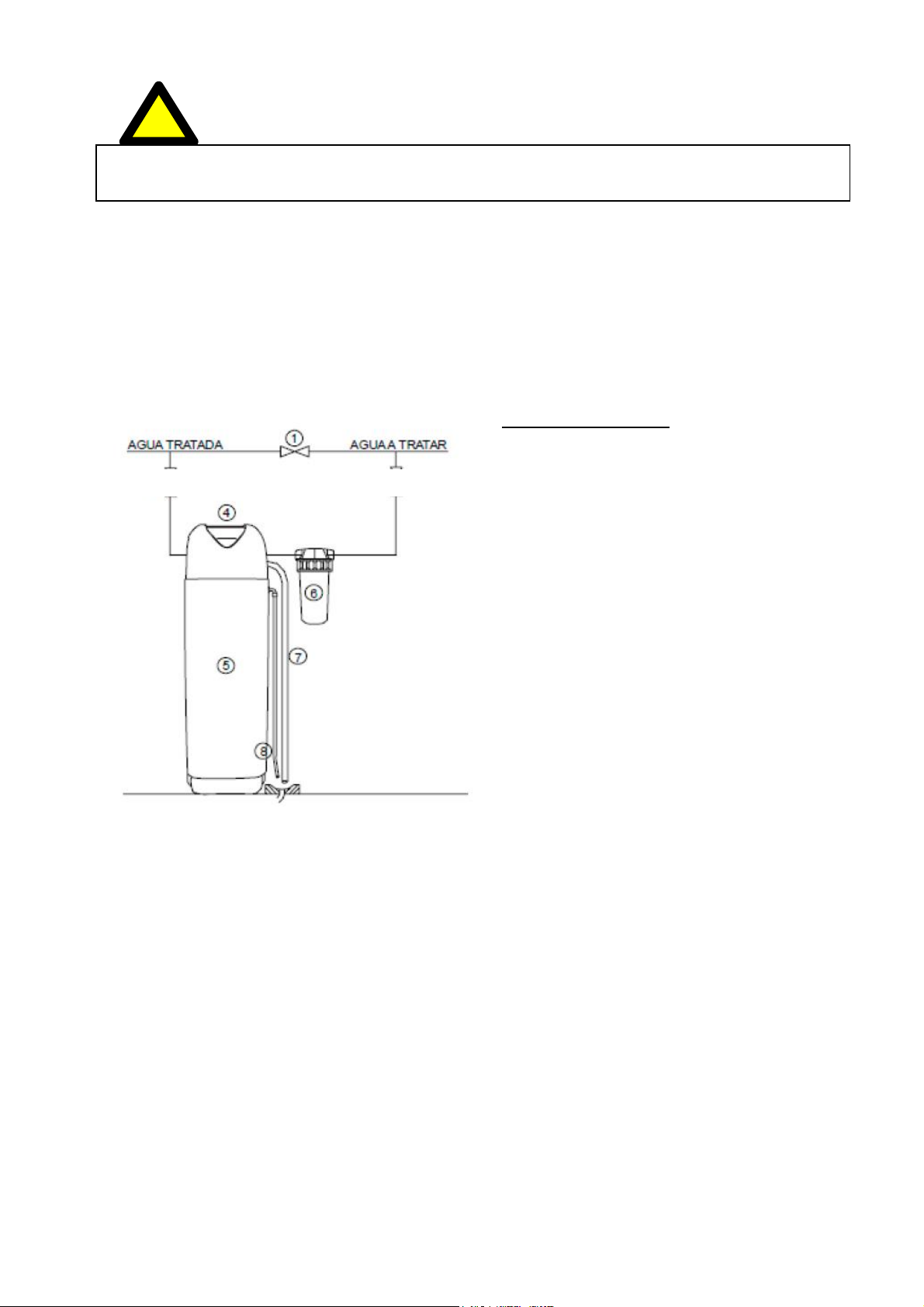
2.1. - SERVICE PHASE
During treatment the water enters the valve through the inlet, flows into the top of the bottle, flowing through the
resin bed in descending order thereby producing the ion exchange process.
The treated water is sent through the outlet connection to the service.
2.2. - REGENERATION PHASE.
Once the resin bed has retained all of the calcium and magnesium ions they must be regenerated for
a new cycle.
The regeneration process consists of 4 steps aiming at the regeneration of the resin bed and its
preparation for the new cycle.
Softeners from the CURVE, D-UF and D-DF series automatically switch between operating and
regeneration phases without the user having to manipulate the system.
The final user should only keep the brine tank full of salt for softeners.

3
ref: MA-ED-0008-EN-V16.0-MIÑO DESCALCIFICADOR D-DF-M3 & D-UF-M3.pdf
3. - GENERAL TECHNICAL CHARACTERISTICS.
Working pressures:
- Minimum pressure: 2,5 kg/cm²
- Maximum pressure: 6 kg/cm²
If the pressure is less than 2.5 Kg / cm² a pumping system must be installed to ensure the flow and pressure
required. If the pressure is greater than 6 Kg / cm² a pressure reducer must be installed.
Operating temperatures:
- The equipment should not be supplied with hot water (T> 36 ° C).
- The room temperature should be between 1-45 ° C.
Component materials:
- Valve: Reinforced Noryl.
- Bottle: Wound of reinforced polyester with fiberglass.
- Deposit: Made with P.E.
Resin:
- Softening cationic resin, regenerable with NaCl.
4. - ASSEMBLY, INSTALLATION.
4.1. - Previous warnings.
The softening systems D-DF and D-UF series ARE NOT WATER PURIFYING SYSTEMS, there only
purpose is to remove hardness.
If the water supply does not come from public supply network or is from an unknown origin,
performing a physical-chemical and bacteriological analysis will be necessary to ensure the proper functioning
of the water softener equipment, please contact your dealer so they can advise you in these circumstances.
The water supply must be suitably filtered, so installing sediment prefilter to facilitate the removal of
suspended particles in order to protect internal parts of the valve affecting its operation is recommended.
4.2.
Installation.
The system operation can only be performed by technically qualified personnel.
Instalment requirements & recommendations:
4.2.1.
Select the location of the instalment.
The adequate place where you choose to put the system must have easy access to access the
system and also to fill up the salt tank.
The system must be placed on a flat surface, protected from direct sunlight, rain and
humidity.
The system (including the overflow and drain lines) must be placed where the temperature is
not below 1ºC or above 49ºC.
The system mustn’t be installed near acid nor vapours, or be exposed to products derived
from petroleum, to avoid the risks of deflagration and explosion.

4
ref: MA-ED-0008-EN-V16.0-MIÑO DESCALCIFICADOR D-DF-M3 & D-UF-M3.pdf
The company HIDRO-WATER, S.L. will not be responsible, if the user fails to obey these
recommendations and warnings.
Water softeners must be installed and connected to the inlet, output and drain tubes according
to the manufacturer's instructions and in compliance with current regulations on low voltage
electrical and hydraulic installations.
Do not install any unit between the outlet of the softener and the inlet of the water heater
within less than 3m of piping. If there is a heating element in the system, a non-return valve must be
installed to prevent the hot water damaging the water softener.
COMPACT SOFTENER
Figure 1.
Compact softener installation diagram.
TREATED WATER
UNTREATED WATER
1. By-pass valve.
2. Softener inlet valve
3. Softener outlet valve
4. Cabinet cover.
5. Cabinet (Bottle container and brine tank)
6. Clarifying filter.
7. Drain line.
8. Overflow line.
9. Drain.

5
ref: MA-ED-0008-EN-V16.0-MIÑO DESCALCIFICADOR D-DF-M3 & D-UF-M3.pdf
5
4.2.2. Connecting the system to the water line.
Connecting the system to the mains water must be performed with the corresponding By-pass (figure
2), either byusing the original by-pass or with 3 ball valves installed in the pipeline.
Below is the diagram of the positions of the original by-pass ball valves which come with the system.
Figure 2.
Diagram of the original by-pass positions.
BY-PASS POSITION
OUTLET
INTLET
IN SERVICE POSITION
OUTLET INLET
With the valves in By-pass position, the
water supply won’t enter the softener.
Untreated water will be supplied to the
system.
With the valves in the in service position, the
water supply will enter the softener.
Water will be supplied to the system through
the softener.
The inlet and outlet of the bypass are indicated by the corresponding arrows.
WARNING: The water supply should be adequate to the flow of water to be treated,
with a pressure between 2.5 and 4Kg/cm². If the pressure is less than 2.5Kg/cm² a
pump system must be installed to ensure the required flow and pressure. If the
pressure is greater than 6Kg/cm² a pressure reducer must be installed.

6
ref: MA-ED-0008-EN-V16.0-MIÑO DESCALCIFICADOR D-DF-M3 & D-UF-M3.pdf
The drain outlet provided in the softener’s valve and the salt tank’s overflow lead to the drain. These
connections are independent of each other and have individual discharge to avoid any return.
Connecting the equipment to pipelines must be done with flexible hoses, which must comply with
current regulations, to prevent tensions and possible breakages in the valve’s Noryl head.
4.2.3.
Drain line connection
The system should be located as close to a drain as possible.
The drain level will be below softener’s valve and less than 3 meters away. If this isn’t the case,
please consult our technical department.
The drain line connection will be done with a flexible hose which has an interior diameter (of
15mm.
IMPORTANT:The drain hose mustn’t be connected to a ditch, drain line or sewer. Always
leave an air gap between the drain and the general drain to prevent the possibility
of return through the drain. This could affect the system working properly.
Figure 3.
Drain line and overflow connections.
4.2.4.
Brine line connection
It will be necessary to install a brine tube and connect it to the suction inlet, on which will be
screwed on. Insure that the filter, insert and cone which are supplied with the kit have been
connected correctly
Suction intake Filter Insert Cone Nut Connection description
Check that all the fittings and couplings are tightened so that there is no air intake.

7
ref: MA-ED-0008-EN-V16.0-MIÑO DESCALCIFICADOR D-DF-M3 & D-UF-M3.pdf
4.2.5.
Overflow line connection
The brine tank’s safety overflow leads the overflow to the drain rather than it spilling all over the
floor.
It is ESSENTIAL to install the overflow attachment that comes with the system.
To install the overflow line, the overflow attachment must be placed on the hole which is on the side
of the brine tank, being fixed by the plastic nut and gasket as shown (Figure 4)
For compact systems, the overflow attachment can be found in a bag and can be fitted on the
corresponding side of the cabinet, depending on the location of the system.
Fix a piece of tubing with an interior diameter ( of 15mm to the attachment and hang it so it reaches the
drain.
Connect a tube or flexible
hose with an interior
diameter ( of 15mm.
Figure 4.
Tank’s overflow attachment.
4.2.6.
Electrical connections.
Once the previous connections have been made, the softener’s valve programmer must be
connected to the mains supply (220V-50Hz), via the transformer supplied with the system.
The electrical installation of the equipment must be carried out following the appropriate wiring
regulations. The power line must be foreseen by proper protection devices. (Breaker and
differential).
IMPORTANT: The system must be connected to a separate lighting line, 24 hours a day, NEVER to
any line connected to motors.
The company HIDRO-WATER, S.L. will not be held responsible if the user fails to obeythe
recommendations and warnings.

8
ref: MA-ED-0008-EN-V16.0-MIÑO DESCALCIFICADOR D-DF-M3 & D-UF-M3.pdf
5.
PROGRAMMING.
Once the power supply adapter has been connected, the programmer must be programmed.
Figure 5.
Programmer Front panel.
KEY
DESCRIPTION
ADVANCE.
Moves the pointer to set the parameters.
TIME & DAY.
Access to programme the time and day.
INCREASE VALUES AND CONFIRMATION.
Increases the value of the parameters to configure. Confirms the programmed values.
MODE.
Access to configure regeneration mode.
SET REGEN.
Access toconfigure theparameters of theregenerationmodeselected.
SET CYCLE.
Access to the configuration of the regeneration cycle times.
MANUAL REGEN.
Forced manual regeneration.

9
ref: MA-ED-0008-EN-V16.0-MIÑO DESCALCIFICADOR D-DF-M3 & D-UF-M3.pdf
+
5.1. - DAY & TIME CONFIGURATION.
Steps to follow:
Access to the configuration menu.
Move the cursor over the clock to set the
hour and minute.
+
Move
Increase value
Move the cursor over the weekly
calendar to set the day.
Move
Confirm
Save the programmed values.

10
ref: MA-ED-0008-EN-V16.0-MIÑO DESCALCIFICADOR D-DF-M3 & D-UF-M3.pdf
5.2. - WORK MODE CONFIGURATION
Valve D allows configuration of 4 different working modes:
MODE 1: TIMED - Chronometrical regeneration Work Mode.
The system will regenerate with the frequency of the days selected and the time established
(01-99 days)
Once programmed, the screen will show the
following: TIME OF
DAY
DAY OF
THE WEEK
TIME UNTIL NEXT
REGENERATION. STATE
MODE 2: METER IMM –Volumetric mode with immediate regeneration.
The system will regenerate immediately when the volume of treated water has run out.
Once programmed, the screen will show
the following: TIME OF
DAY
DAY OF THE VOLUMETRIC
WEEK CONTROL
INDICATOR
AVAILABLE
VOLUME
STATE
MODE 3: WEEK –Work mode with weekly chronometrical regeneration. The system will
regenerate on the days of the week selected, at the time established.
Once programmed, the screen will show
the following: TIME
OF DAY
DAY OF
THE WEEK
TIME & DAY UNTIL NEXT
REGENERATION STATE
MODE 4: METER DELAY –Volumetric mode with delayed regeneration.
The system will regenerate at the programmed time once the volume of treated water has run out.
Once programmed, the screen will show
the following: TIME OF
DAY
DAY OF VOLUMETRIC
THE WEEK
CONTROL
INDICATOR
AVAILABLE DELAYED
VOLUME REG. INDICATOR STATE

11
ref: MA-ED-0008-EN-V16.0-MIÑO DESCALCIFICADOR D-DF-M3 & D-UF-M3.pdf
+
5.2.1. - WORK MODE CONFIGURACION DEL: MODE 1 - TIMED.
To access the Work Mode, press: Steps to follow:
Access to the configuration menu.
Move the cursor to the desired work
configuration: (TIME).
+
Move
Confirm
Save the programmed values.
5.2.1.1- TIMED CONFIGURATION & INTERVAL BETWEENREGENERACIONS:
MODE 1 - TIMED
To access the Work Mode, press: Steps to follow:
Access to the configuration menu.
Move the cursor to the desired
regeneration time.
+
Move Increase
value
Move the cursor to set the number of
days between regenerations.
Move
Increase
value
Save the programmed values.

12
ref: MA-ED-0008-EN-V16.0-MIÑO DESCALCIFICADOR D-DF-M3 & D-UF-M3.pdf
L
L
5.2.2. - WORK MODE CONFIGURATION: MODE 2- METER IMM.
To access the Work Mode, press: Steps to follow:
Access to the configuration menu.
Move the cursor to the desired work
configuration: (METER IMM).
+
Move Confirm
Move the cursor and confirm the desired
measurement units: (L)
+
Move Confirm
Save the programmed values.
5.2.2.1. - VOLUME OF TREATED WATER CONFIGURATION:
MODE 2 - METER IMM.
To access the Work Mode, press: Steps to follow:
LAccess to the configuration menu.
Move the cursor to set the volume of
water that can be treated by the
softener’s resin bed.
+
Move Increase value
SEE THE TABLE ATTACHED TO SET THE
LITRES OF TREATED WATER.
Save the programmed values.

13
ref: MA-ED-0008-EN-V16.0-MIÑO DESCALCIFICADOR D-DF-M3 & D-UF-M3.pdf
+
5.2.3. - WORK MODE CONFIGURATION: MODE 3 - WEEK
To access the Work Mode, press: Steps to follow:
Access to the configuration menu.
Move the cursor to the desired work
configuration: (WEEK).
+
Move Increase value
Save the programmed values.
5.2.3.1. - REGENERACION TIME & DAY CONFIGURATION.
MODE 3-
WEEK
To access the programming of the regeneration time, press: .
Access to the configuration menu.
Move the cursor to set the
regeneration time desired.
+
Move Increase
value
Move the cursor to set the days that
we wish regenerations to happen on.
Move
Confirm
regenerationdays.
Save the programmed values.

14
ref: MA-ED-0008-EN-V16.0-MIÑO DESCALCIFICADOR D-DF-M3 & D-UF-M3.pdf
5.2.4. - WORK MODE CONFIGURATION: MODE 4-METER DELAY
To access the Work Mode, press: Steps to follow:
Access to the configuration menu
Move the cursor to set the regeneration time
desired: (METERDELAY).
+
Move Confirm
Move the cursor and set the desired measurement
Units: (L).
+
Move Confirm
Save the programmed values.

15
ref: MA-ED-0008-EN-V16.0-MIÑO DESCALCIFICADOR D-DF-M3 & D-UF-M3.pdf
5.2.4.1. - REGENERATION TIME & TRETED WATER VOLUME
CONFIGURATION: METER DELAY
To access the ‘programming of the regeneration time, press:.
.
Access to the configuration menu.
Move the cursor to set the
regeneration time desired:
+
Move Increase
value
Move the cursor to set the maximum
number of days between regenerations.
+
Move Increase
value
Move the cursor to set the volume
that the softener’s resin bed can treat.
+
Move Increase
value
SEE THE TABLE ATTACHED TO SET
THE VOLUME OF WATER TREATED
DEPENDING ON THE SOFTENER’S
RESIN BED.
Save the programmed values.
SAVE THE VALUES

16
ref: MA-ED-0008-EN-V16.0-MIÑO DESCALCIFICADOR D-DF-M3 & D-UF-M3.pdf
CALCULATION TABLE TO PROGRAMME THE VOLUME OF TREATED WATER
BY A D-DF-M3 SYSTEM DEPENDING ON THE RESIN AND HARDNESS OF THE
WATER.
HARDNESS ºHF FOR D-DF-M3 SYSTEMS
Litres of resin 30 ºHF
40 ºHF
50 ºHF
60 ºHF
70 ºHF
80 ºHF
90 ºHF
100 ºHF
5
1000
750
600
500
429
375
333
300
8
1600
1200
960
800
686
600
533
480
10
2000
1500
1200
1000
857
750
667
600
12
2400
1800
1440
1200
1029
900
800
720
15
3000
2250
1800
1500
1286
1125
1000
900
20
4000
3000
2400
2000
1714
1500
1333
1200
30
6000
4500
3600
3000
2571
2250
2000
1800
40
8000
6000
4800
4000
3429
3000
2667
2400
50
10000
7500
6000
5000
4286
3750
3333
3000
60
12000
9000
7200
6000
5143
4500
4000
3600
80
16000
12000
9600
8000
6857
6000
5333
4800
100
20000
15000
12000
10000
8571
7500
6667
6000
125
25000
18750
15000
12500
10714
9375
8333
7500
e.g.: for 30 litres of resin & 50 ºHF of hardness, programme: 3600 litres
. - The values shown in the D-DF-M3 table have been calculated for an exchange capacity established by
HIDRO-WATER.
. - Depending on the amount of salt used for regenerating, the values shown in the table may vary.
CALCULATION TABLE TO PROGRAMME THE VOLUME OF TREATED WATER
BY A D-UF-M3 SYSTEM DEPENDING ON THE RESIN AND HARDNESS OF THE
WATER.
HARDNESS ºHF FOR D-UF-M3 SYSTEMS
Litres of resin
30 ºHF
40 ºHF
50 ºHF
60 ºHF
70 ºHF
80 ºHF
90 ºHF
100 ºHF
14
2100
1575
1260
1050
900
788
700
630
18
2700
2025
1620
1350
1157
1013
900
810
22
3300
2475
1980
1650
1414
1238
1100
990
35
5250
3938
3150
2625
2250
1969
1750
1575
48
7200
5400
4320
3600
3086
2700
2400
2160
73
10950
8213
6570
5475
4693
4106
3650
3285
100
15000
11250
9000
7500
6429
5625
5000
4500
136
20400
15300
12240
10200
8743
7650
6800
6120
e.g.: for 35 litres of resin & 50 ºHF of hardness, programme: 3150 litres
. - The values shown in the D-UF-M³ table have been calculated for an exchange capacity established
by HIDRO-WATER.
. - Depending on the amount of salt used for regenerating, the values shown in the table may vary.

17
ref: MA-ED-0008-EN-V16.0-MIÑO DESCALCIFICADOR D-DF-M3 & D-UF-M3.pdf
5.2.3. - CONFIGURATION OF REGENERATION CYCLE TIMES.
To access the programming of the regeneration time, press: .
Access to the regeneration cycle times
configuration menu.
Move the cursor to set the minutes of
each cycle.
+
Move Increase
value
SEE THE TABLE ATTACHED TO SET
THE VOLUME OF WATER TREATED
DEPENDING ON THE SOFTENER’S
RESIN BED
Save the programmed values.
.

18
ref: MA-ED-0008-EN-V16.0-MIÑO DESCALCIFICADOR D-DF-M3 & D-UF-M3.pdf
TIMING PROGRAMME FOR D-DF-M³ SYSTEMS
LITRES
OF
RESIN
BACKWASH
BRINE DRAW
RAPID RINSE
REFILL
5
5 min
60 min
5 min
5 min
8
5 min
60 min
5 min
8 min
10
5 min
60 min
5 min
8 min
12
5 min
60 min
5 min
10 min
15
5 min
60 min
5 min
10 min
20
5 min
60 min
5 min
15 min
30
5 min
65 min
5 min
20 min
40
10 min
65 min
10 min
25 min
50
10 min
65 min
10 min
15 min
60
10 min
65 min
10 min
20 min
80
10 min
65 min
10 min
15 min
100
10 min
65 min
10 min
15 min
125
10 min
65 min
10 min
20 min
TIMING PROGRAMME FOR D-UF-M³ SYSTEMS
LITRES
OF
RESIN
BACKWASH
BRINE DRAW
RAPID RINSE
REFILL
14
5 min
60 min
5 min
4 min
18
5 min
60 min
5 min
6 min
22
5 min
60 min
5 min
8 min
35
5 min
60 min
5 min
12 min
48
10 min
60 min
10 min
10 min
73
10 min
60 min
10 min
15 min
100
10 min
65 min
10 min
10 min
136
10 min
65 min
10 min
15 min

19
ref: MA-ED-0008-EN-V16.0-MIÑO DESCALCIFICADOR D-DF-M3 & D-UF-M3.pdf
6. - SOFTENER START-UP
Once the hydraulic circuit has been realised, connected to a power source and the microprocessor has been programmed,
the system can be started up. Follow the steps as described below:
6.1. - How to start up the softener.
Bleed the air bottle
-
- Make sure that the softener’s inlet and outlet valves are closed and the bypass is open to assure that there is
water in the system.
-
Hold the MANUAL REGENRATION button for 5 seconds; after so a manual regeneration will begin. The
controller will send an order so that the piston moves to the CYCLE 1 position, BACKWASH.
Keep in mind that the motor takes a while to move onto the next cycle, and it is indicated that is moving with
the flashing message "GO TO + NEXT CYCLE NAME". Until that message disappears from the screen, you
cannot advance to the next cycle
-
Once the piston is allocated in the backwash position, open the inlet valve very slowly a ¼ of the way allowing
water to enter the system.
-
Allow all of the air to be released from the resins bottle. Once all of the air has been bled (Water starts flowing
slowly through the drain), slowly open the supply valve fully.
-
Let the water drain away until it turns completely clear.
WARNING: If the valve is opened too much or too quicklyresin can be lost. In this position
you must hear how the air escapes slowlythrough the drain line.
Start up
-
Next, PRESS & RELEASE the MANUAL REGENERATION button to manually advance the regeneration cycles.
Repeat this operation until you reach CYCLE 4, REFILL in order to bleed the brine line of air. Let the w ater
flow and bleeds all of the air bubbles from the suction line. Once bled:
-
Let the system fill the brine tank itself. Afterwards, advance the cycle to SERVICE.
-
Next, you must check that the system is sucking. In the SERVICE position, press the MANUAL
REGENERATION button for 5 seconds to start another regeneration and advance the cycles to CYCLE 2,
BRINE, just as we’ve described before. Visually verify the system is sucking water from the salt tank and is
able to remove the water from the brine tank completely. The suction must be constant and the water level in
the tank must go down. For a further good subsequent performance, it is critical to check this. If you take air in
the suction line, cancel the regeneration by advancing the cycles to SERVICE, review and tighten the
components of the suction line and then perform the check.

20
ref: MA-ED-0008-EN-V16.0-MIÑO DESCALCIFICADOR D-DF-M3 & D-UF-M3.pdf
-
Once the system has been checked that it’s sucking correctly, replace the volume of water that had been sucked
by setting the system to REFILL & and allow it to go to SERVICE by itself.
-
The display will show the following information according to the mode set:
MODE 1: TIME MODE 2: WEEK
MODE 3: METER IMM MODE 4: METER DELAY
-
Fill the brine tank with salt specifically for softeners either in tablets or type-3 grain and the system is ready for
operation.
-
-
At this time and you can have softened water, close the bypass and open the softener's outlet valve.
-
Check that the turbine works correctly by opening a tap (faucet) and check that the treated water on the
display decreases.
Softened water regulation
-
For domestic consumption, a residual hardness of 8 to 10ºF is recommended. To adjust the hardness, half
open the built-in mixing controller which is on the same valve.
-
Check the hardness by analyzing the water from the outlet of the softener.
Figure 6. Detailed mixing screw.
If the system is without use for a period of a month or more, it must be disinfected with the HW*77 product.
Likewise, it is recommended that the system is disinfected every 6 months with the HW*77 product.
Consult the technical department at HIDRO-WATER, S.L.
This manual suits for next models
3
Table of contents
Popular Water Dispenser manuals by other brands

Whirlpool
Whirlpool WHES20 Installation and operation manual

Haier
Haier WDNS045 user manual

H2OPTIMO
H2OPTIMO H2O-CS-ECO Technical manual

GE
GE SmartWater GXSF18G Owner's Manual & Installation Instructions

vitapur
vitapur VWD866W-3 Use & care guide

Lancaster Water Treatment
Lancaster Water Treatment XFactor 7-PEL-75B Installation, operating and service manual