97160C (Rev. D - 10/16)
EHFRA7C*A EHFRA7FC*A
Page 3
INSTALLATION INSTRUCTIONS
1. Remove shipping brace from mounting box and discard.
2. Fasten mounting box into wall cutout using screws or bolts (provided by others) through holes or knockouts
provided on each side of the mounting box. (See Fig. 1)
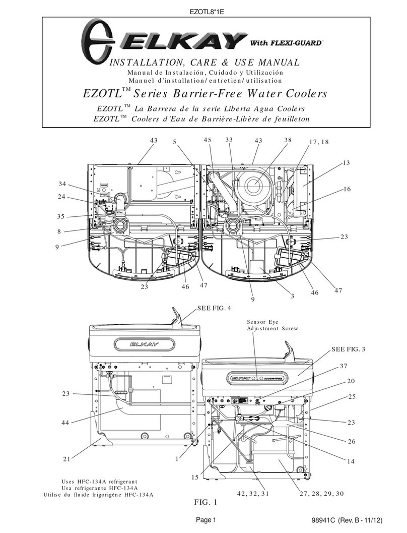
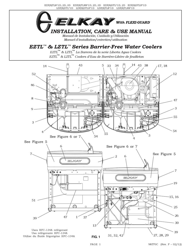
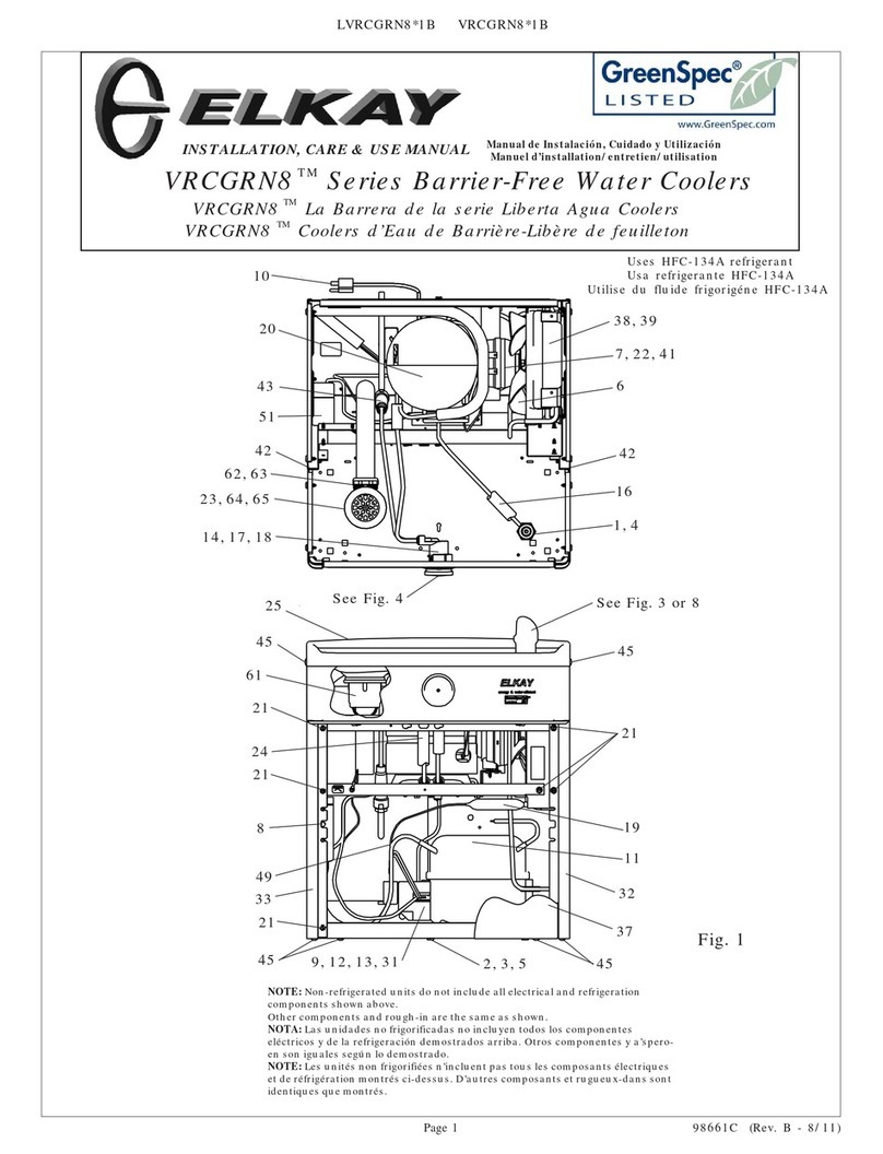
3. Place refrigeration package into mounting box and connect water lines. (See Fig. 1)
4. Remove access panel (on bottom of mounting box) and install fountain body.
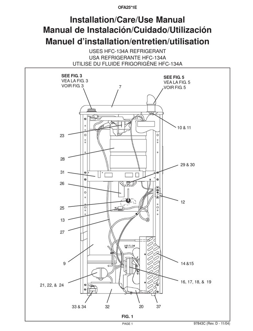
5. Connect water outlet tube on refrigeration package to water in tube on regulator holder (Item 1) with tubing and tting
provided. (See Fig. 2)
** For glassller models see g. 3.
6. Water inlet is 3/8" O.D. and waste tube is 1-1/4" O.D. Contractor is to supply waste trap and service stop valve in
accordance with local codes.
7. Connecting lines to be unplated copper and thoroughly ushed to remove all foreign matter before connecting to refrigeration
package. The furnished strainer (Item 28) should be added to the supply line.
8. Connect the refrigeration package to the supply line with a shut off valve and install a 3/8" (10mm) unplated copper water line
between the valve and the cooler. Remove burrs from outside of waterline. Insert water line straight into the ttings until they
reach a positive stop, approximately 3/4". (See Figs. 6 and 7) DO NOT SOLDER TUBES INSERTED INTO THE STRAINER AS
DAMAGE TO THE O-RINGS MAY RESULT.
9. Electrical: Insure power supply is identical in voltage, hertz, and phase to that specied on the refrigeration package serial
plate. Never wire compressor directly to the power supply.
10. Turn water supply on and check thoroughly for leaks.
11. Release air from tank by depressing push bar; a steady stream of water assures all air is removed.
12. Re-check for leaks.
13. Stream height is factory set at 35 PSI. If supply pressure varies greatly from this, turn adjustment screw on regulator (Item
22). Clockwise adjustment will raise the stream height and counter-clockwise adjustment will lower stream height. For best
adjustment, stream should hit basin approximately 6-1/2" from the bubbler.
14. Rotate fan blade on refrigeration package to insure proper clearance and free fan action.
15. Connect power supply.
16. Replace access panel and install grill using #8 x 1.00" (25mm) PH screws and small clips provided.
TROUBLE SHOOTING AND MAINTENANCE
1. Orice Assy: Mineral deposits on orice can cause water ow to spurt or not regulate. Mineral deposits may be removed
from orice with a small round le not over 1/8 diameter or a small diameter wire. CAUTION: Do not le or cut orice
materials.
2. Actuation of Quick Connect Water Fittings: Cooler is provided with lead-free connectors which utilize an o-ring water
seal. To remove tubing from the tting, relieve water pressure, push in on the gray collar while pulling on the tubing (See Fig. 7).
To insert tubing, push tube straight into the tting until it reaches a positive stop, approximately 3/4".
3. CAUTION: Cleaning of Bronzetone models requires special care. Outer surfaces must be cleaned with a mild detergent or a
mixture of vinegar and water only, rinsed and wiped dry. Abrasive and acidic cleaners may eventually damage the Bronzetone
nish.
18
28
19
28
FIG. 3FIG. 2
EHFRA7C EHFRA7FC
Note: Danger! Electric shock hazard. Disconnect power before servicing unit.
