AVSO
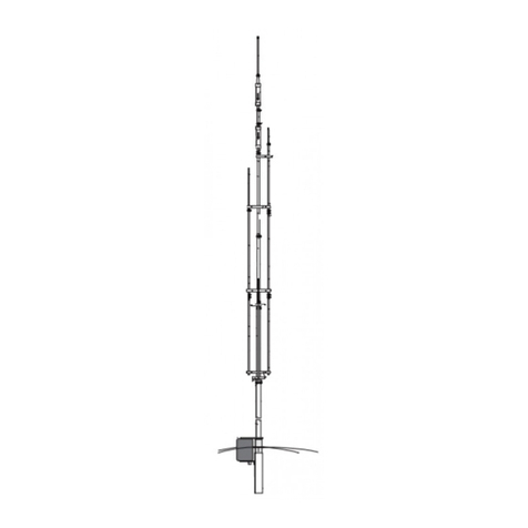
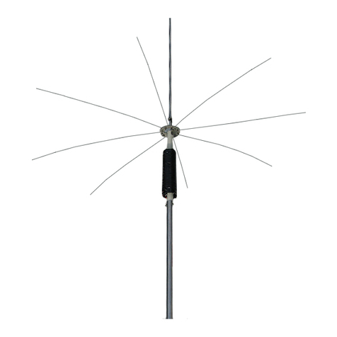
your Cushcraft AVg0 is a loaded 1/g wave antenna that can be either switched between the 75 meter SSB band and the 80 meter CW band remotely or set up
for iixed operation on either end of the band. lt is designed to operate at full power for long periods of time. lt is a convenient size and is easily assembled.
WARNING
THIS ANTENNA IS AN ELECTRICAL CONDUCTOR, CONTACT WITH POWER LINES CAN RESULT IN DEATH, OR SERIOUS INJURY. DO NOT
INSTALL THIS ANTENNA WHERE THERE IS ANY POSSIBILITY OF CONTACT WITH HIGH VOLTAGE OR ARC-OVER FROM POWER CABLES
OR SERVICE DROPS TO BUILDINGS. THE ANTENNA, SUPPORTING MAST AND/OR TOWER MUST NOT BE CLOSE TO ANY POWER LINES
DURING INSTALLATION, REMOVAL OR IN THE EVENT PART OF THE SYSTEM SHOULD ACCIDENTALLY FALL. FOLLOW THE GUIDELINES
FOR ANTENNA INSTALLATIONS RECOMMENDED BY THE U.S. CONSUMER PRODUCT SAFEW COMMISSION AND LISTED IN THE ENCLOSED
PAMPHLET.
The Cushcraft AVg0 is designed and manufactured to give trouble lree service. This antenna will perform as specified if the instructions and suggestions in
this manual are followed and care is used in the assembly and installation. When checking the components received in your antenna package use the parts
listed beside each diagram. There is a master parts list on page 2. lf you are unable to locate any tube or component, check the inside ol all tubing.
IMPORTANT: Save thJweight label from the outside of the canon. Each antenna is weighed at the lactory to verify the pans count. lf you claim a missing
part, you will be asked lor the welght verification label. PLANNING
plan your installation carefully. lf you use volunteer helpers be sure that they are qualilied to assist you. Make certain that everyone involved understands
that you are the boss and that they must follow your instructions. lf you have any doubts at all, employ a prolessional antenna installation company to install
your antenna. LOCATION
Location ol the antenna is very important. Sunounding objects such as trees, power lines, other antennas, etc. will seriously reduce etficiency. To minimize
the effects of sunounding objäcts, mount the antenna as much in the clear as possible. EXTREME CARE MUST BE USED FOR YOUR SAFETY' YoU
MUST INSURE THAT WHILE THE AVBO IS IN OPERATION NEITHER PEOPLE OR PETS CAN COME IN CONTACT WITH ANY PORTION OF YOUR
ANTENNA. DEADLY VOLTAGES AND CURRENTS MAY EXIST. ALSO, SINCE THE EFFECTS OF EXPOSURE TO RF FIELDS ARE NOT FULLY
UNDERSTOOD, LONG TERM EXPOSURE TO INTENSE RF FIELDS IS NOT RECOMMENDED. THERE IS A WARNING STICKER WHICH MUST BE
ATTACHED TO THE ANTENNAAS SHOWN IN FIGURE G,
MOUNTING
your mast should be rigid and vertical. Always use a mast at least 1-3/4" (4.4 cm) in diameter. Be sure your mast is very rugged. The wind load of the AV80
wiihiceonitrequiresthatyouprovideastrongmount. Forelevatedmounting,Cushcraftrecommendsal-3l4lo2'(4.4-5.1cm) schedule40metal pipe
be used as the supporting member.
cushcraft recommends suyins the AV80 with u non.onor.#.TI.TlT#,El'J' iiL9rd exposure to weather can be attached to the AVBo ar the
point shown in Figure D. RADIAL SYSTEM
The AVg0 is a low lrequency HF loaded monopole antenna. Pan of the antenna is the ground system. Thele have been volumes written on the merits of
several types of radial systems. We describe two alternatives from among the many. Please choose the approach you prefer. Radial wire should be at least
AWG#16 and strong enough to withstand exposure to weather. Wire can be insulated or bare.
Elevated System - An elevated radial system should be at least B feet (2.5 meters) above the ground. At least lour radial wires, each approximately 1/4
wavelengthiong(68feetor20.7meters) shouldbeplacedsymmetricallyaspossiblearoundtheantenna. Keepwiresagtoaminimum. lfspaceislimited'
the radials can be formed to fit in the space available. Objects between the radials will affect the eleclrical wavelength. The ends ol thre radials should be
insulated lrom their supports.
Ground Mounted System - Mount the antenna base 3 inches (7.6 cm) above the ground. Place 12 or more radial wires 1/4 wavelength (68 feet or 20'7
meters) symmetrically around the antenna.
SYSTEM GROUNDING
Direct grounding of the antenna and mast is very important. This serves as protection from lightning strikes and static buildup, and from high voltage which
is presänt in thJ radio equipment connected to the antenna. A good electrical connection should be made to one or more ground rods (or other.extensive
groundsystem) directlyatthebaseoftheAVS0,usingatleast#l0AWGgroundwireandnoncorrosivehardware. Fordetailsandsafetystandards,consult
the National Electrical Code. You should also use a coaxial lightning arrester. Cushcraft offers several differenl models, such as LAC-1 , LAC-2 and the LAC'
4 series.
ASSEMBLY
Assemble your antenna by following the directions and illustrations in steps 1 through 5. After the antenna is completely assembled, verify dimensions for
accuracy. Then, return to the section below for final tuning.
. . TUNING PROCEDURE
DO NOT MAKE ADJUSTMENTS IN THE MATCHING NETWORK BOX WHILE TRANSMITTING. DOING SO COULD LEAD TO ELECTNOCUTION. AII
tuningisdoneinsidethematchingnetwork. Donotadjustthelengthof theradiator. BycompressingtheturnsonL1,L2andL3(FigureA) theAV80will be
resonant at ihe bottom of the CW and SSB bands. To raise the resonant f requency begin by spreading the turns on L3. To raise the CW resonant frequency
higher, spread the turns on L2. For SSB, spread the turns on L1 .
