manuals.online logo
Brands
  1. Home
  2. •
  3. Brands
  4. •
  5. CUSHCRAFT
  6. •
  7. Antenna
  8. •
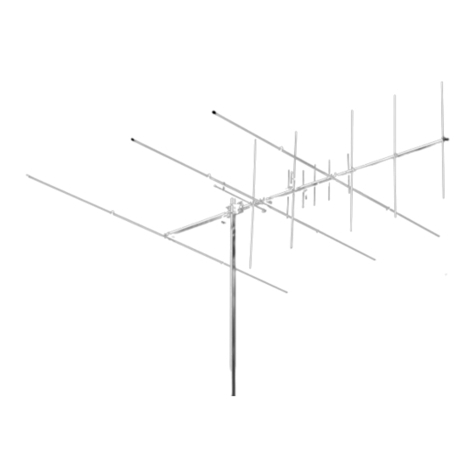
  9. CUSHCRAFT P134-4 Instruction Manual

CUSHCRAFT P134-4 Instruction Manual

This manual suits for next models

10

Other CUSHCRAFT Antenna manuals

CUSHCRAFT AV80 Instruction manual

CUSHCRAFT

CUSHCRAFT AV80 Instruction manual

CUSHCRAFT 15-4CD Skywalker User manual

CUSHCRAFT

CUSHCRAFT 15-4CD Skywalker User manual

CUSHCRAFT MA5V Instruction manual

CUSHCRAFT

CUSHCRAFT MA5V Instruction manual

CUSHCRAFT Ringo Ranger ARX-220 User manual

CUSHCRAFT

CUSHCRAFT Ringo Ranger ARX-220 User manual

CUSHCRAFT Big Thunder X7 User manual

CUSHCRAFT

CUSHCRAFT Big Thunder X7 User manual

CUSHCRAFT MA8040V Instruction manual

CUSHCRAFT

CUSHCRAFT MA8040V Instruction manual

CUSHCRAFT R9 Instruction manual

CUSHCRAFT

CUSHCRAFT R9 Instruction manual

CUSHCRAFT ASL670 Instruction manual

CUSHCRAFT

CUSHCRAFT ASL670 Instruction manual

CUSHCRAFT A270-10S Instruction Manual

CUSHCRAFT

CUSHCRAFT A270-10S Instruction Manual

CUSHCRAFT A50-3S Instruction Manual

CUSHCRAFT

CUSHCRAFT A50-3S Instruction Manual

CUSHCRAFT A147-4 User manual

CUSHCRAFT

CUSHCRAFT A147-4 User manual

CUSHCRAFT A50-6S User manual

CUSHCRAFT

CUSHCRAFT A50-6S User manual

CUSHCRAFT DX-120 User manual

CUSHCRAFT

CUSHCRAFT DX-120 User manual

CUSHCRAFT A627013S Instruction manual

CUSHCRAFT

CUSHCRAFT A627013S Instruction manual

CUSHCRAFT A270-6S Instruction Manual

CUSHCRAFT

CUSHCRAFT A270-6S Instruction Manual

CUSHCRAFT R6000 Instruction manual

CUSHCRAFT

CUSHCRAFT R6000 Instruction manual

CUSHCRAFT A449-6S Instruction Manual

CUSHCRAFT

CUSHCRAFT A449-6S Instruction Manual

CUSHCRAFT A449-6 Instruction Manual

CUSHCRAFT

CUSHCRAFT A449-6 Instruction Manual

CUSHCRAFT A4306SN Instruction Manual

CUSHCRAFT

CUSHCRAFT A4306SN Instruction Manual

CUSHCRAFT 13B2 User manual

CUSHCRAFT

CUSHCRAFT 13B2 User manual

CUSHCRAFT LFA-6M4EL User manual

CUSHCRAFT

CUSHCRAFT LFA-6M4EL User manual

CUSHCRAFT LFA-2M16EL User manual

CUSHCRAFT

CUSHCRAFT LFA-2M16EL User manual

CUSHCRAFT MA5B Instruction manual

CUSHCRAFT

CUSHCRAFT MA5B Instruction manual

CUSHCRAFT A144-20T Instruction Manual

CUSHCRAFT

CUSHCRAFT A144-20T Instruction Manual

Popular Antenna manuals by other brands

DAVIS Windex AV 3160 installation instructions

DAVIS

DAVIS Windex AV 3160 installation instructions

Belden Hirschmann BAT-ANT-N-14G-IP23 Mounting instruction

Belden

Belden Hirschmann BAT-ANT-N-14G-IP23 Mounting instruction

Vtronix YHK Fitting instructions

Vtronix

Vtronix YHK Fitting instructions

KVH Industries TracVision 6 Technical manual

KVH Industries

KVH Industries TracVision 6 Technical manual

Leica Geosystems GS10 user manual

Leica Geosystems

Leica Geosystems GS10 user manual

Sirio Antenne Gain-Master manual

Sirio Antenne

Sirio Antenne Gain-Master manual

Sony VCA-41 Installation/connections

Sony

Sony VCA-41 Installation/connections

ZCG Y100 Series installation guide

ZCG

ZCG Y100 Series installation guide

Advantech Wireless INTREPID120 Assembly instructions

Advantech Wireless

Advantech Wireless INTREPID120 Assembly instructions

Cerio ANT-10AO installation guide

Cerio

Cerio ANT-10AO installation guide

Alfa Network APA-L01 Specifications

Alfa Network

Alfa Network APA-L01 Specifications

Naval PR-422CA Operation manual

Naval

Naval PR-422CA Operation manual

Feig Electronic ID ISC.ANTH200/200 Series manual

Feig Electronic

Feig Electronic ID ISC.ANTH200/200 Series manual

TERK Technologies TV44 owner's manual

TERK Technologies

TERK Technologies TV44 owner's manual

TERK Technologies SIR3 owner's manual

TERK Technologies

TERK Technologies SIR3 owner's manual

Directive Systems & Engineering DSE2324LYRMK quick start guide

Directive Systems & Engineering

Directive Systems & Engineering DSE2324LYRMK quick start guide

HP J8999A instructions

HP

HP J8999A instructions

MobilSat MSP-S Mounting instructions

MobilSat

MobilSat MSP-S Mounting instructions

manuals.online logo
manuals.online logoBrands
  • About & Mission
  • Contact us
  • Privacy Policy
  • Terms and Conditions

Copyright 2025 Manuals.Online. All Rights Reserved.

www.SteamPoweredRadio.Com
ASSEMBLY AND INSTALLATION
4 Element
Economy Yagis
951339(11/94)
www.SteamPoweredRadio.Com
INSTALLATION
SUGGESTIONS
Your Cushcratt\/HF
beam
is
designed
and
manufactured
to
gi
ve
t
op
performance
and
troub
lefree
serv
i
ce
.Theantennawill
perform
asspe
cif
ied,
if
the instructions
a:i
d suggestions are followed, and if
care
is
used in assembly
and
installation.
MAST:
The
antenna may
be
mo
unted
on a
mas
t
diameter
up
to
2 inches (5.1
cm)
.
MOUNTING
:When
:nounting
more
than
one
beam
on
the same mast, theyshould be
mounted
at
least 1
/,
wave-length (of the lower frequency)
away from
other
antennas,
Ge
nerally,
it
is
best
to
mount
these beamsabove tower frequencyaniennas.
LOCATION
:Locationoftheantennais very
important.
Surrounding
objectssuchastrees,
power
lines,
othe
r antennas,
etc
.willseriouslyreduce
efficiency.
To
minimize
the
ettects
of
surrounding
ob
ject
s,
mountthe
antennaas
hig
h andIntheclear
as
possible
.
If
metal
guy
wires
are
used,they
should
be
broken
into
non-re~onant
lengths
with stra
in
Insulators.
WARNING:THIS ANTENNAIS
AN
ELECTRICALCONDUCTOR,CONTACTWITH POWER LINESCANRESULTINDEATH,
OR
SERIOUSINJURY.
DO N
OT
INST
AL
L THIS ANTENNAWHERETHERE IS ANY POSSIBILITYOF CONTACTWITH ORHIGH VOLTAGE A
RC
-OVERFROM POWER
CA
BLESORSERVICEDROPSTOBUILDINGS.THEANTENNA,SUPPORTING
MAST
AND/ORTOWER
MUST
N
OT
BE CLOSETO ANY POWER
LINES DURING INSTALLATION-REMOVAL OR IN
THE
EVENT PART
OF
TH
E SYSTEM SHOULD ACCIDENTALLY FALL. FOLLOW THE
GUIDELINES FORANTENNAINS
TA
LL
ATIONSRECOMMENDED BYTHEU.S. CONSUMER PRODUCT
SA
FETY
COM
MISSIONAND LISTEDIN
THE PAMPHLET THAT
CA
ME WITH YOUR ANTENNA.
ASSEMBL
V
INSTRUCTIONS
ELEMENT
ASSEMBLY:
The
elements
except
for
the
dipole
are
taPE'(I
together.They
are
progressively
shorter
from
reflectorto
directors.Using
fi
gure
1
mount
the longest
element
near the holes
for
theu-bolts. Next
using
figure
2
mount
the
dipole
. Now
mount
t
he
longer of the remaining
elements
next
to
the
dipole
and
then
mount
the
remaining element
at
the
end
of the
boom.
MAST
MOUNT:
The
boom
is
designed
for
either
vertical
or
horizontal polarization. Refer
to
figure
3 and
mount
the
u-bolt
to
the
boom
and mast.
When
verti
cally polarized,
the
Reddi-Match
rod
should
be
pointing
up
.
TUNING:
The R
eddi-Match
is
set
at
the
factory
for
50-ohm
and
center
band
operation
.
If
retuning becomes necessaryuse a
good
qu
alitywatt
meter.
It
is
not
necessary
to
cut
your
feedllne
or
p
rune
It
to
a
particular
length;
any
length
cable
may
be
usedwith
the
beams. However, the
cable
should
be
as
short
as
possible
to
redu
ce
feed
line
losses.
Your
cable
should
be
equ
i
pped
witha standard PL-259
coax
ia
l titting,
to
connect
to
the
Redd
i-
Match,
figure
2.
Tune
the
antenna
at
your
center
frequency
;
using
a
50-ohm
feedl
in
e
from
your
transmitter
,and a
watt
meter.
Connect
the
wa
ttmeter
to
the
antennawi
th
a
short
length
of
50
ohm
coaxialcable.
Set
the
wa
tt
meter
for
reflected
power.
If
therefle
cted
power
ls
high,
loo
sen
thetuning
strap
and
adjust
it
slightly
In
either
direction
. Movea
wa
yf
rom
theantennaand
check
the
reading
.
If
the
reflected
power
Increased,
move
thestrapback
to
its original posit
io
n
and
adjust
in
the
opposite
direction.
If
the
reflected
power
dropped
, repeat
the
adjustment
procedure
until you achieve
minimum
reflected
power
on
the
wa
tt
meter.Disconnectthe
cable
andwatt
meter,
and
tighten
the
tu
ning
strap
secu
re
ly.
Use
the
vinyl
boot
on the
coax
ia
l
cable
to
the
beam
to
Insure a weather
proof
connection.
Coat
the
outside
of
the
alumi
num
connector
threads
and the PL-259'swiththe
sill
cone
grease
provided
.
Do
not
coat
the
connector
center
pin
or
socke
twithsilicone.
Slide
the
vinyl
boot
over
the
connector
and
against
the
brae-
ket
for
a
good
weather
tight
connection
,
figure
2B. Run
the
coaxial feedllne
along
the
boom
and
down
the
mast
using
electrical
tape
to
hold
it
in
posit
io
n.
STACKING
FOR
MORE
GAIN
Two
Econo
my
beams
may
be
stacked
for
3dB
IncreaseusingtheP14-VPK
stacking
kit.
The
kit
includesahorizontal
support
boom,
hardware
and RG-59/U
cable
harness.
Four
beams
may
be
s
tacked
w
it
h
two
P14-VPK kits
and
a
power
divider
for
6dB
Improvement
in
ga
in.
Seefi
gure
5
for
stacking
dimensions
and
illustrations.
ELEMENT A
SSE
MB
LY .)
PIN
KE
Y
DISPLAY
DcSC
.
SIZE
QTY
020021
21
e):==
Mact-il
ne
#10-24
X 2" 3
21
S
crew
5.
08cm1
020022
22
~
Hex
Nut
#10
-
24
3
1900
25
25
Alumirn..1m
'/
•"
(2
22cm)
3
:
')-P.
B
ra
cket
1900
28 28
~
t
◄
al!
Washe
r
1·
(2
.
54cm
) 3
29
{!j:)
020029
29 @ Loci< W
as
ne
r
#10
3 J E#
E#
,-,.r
--
..
El
em
e
nt
S
ee
El
em
en
t
28
Ch
a
rt
ELEMENT CHART
~~
FREQUE
N
CY
RANGE
AND
ELEMENT
LENGTHS
MODEL
P
\34
◄
P133_.
P142-t
P
146
◄
P150-C
P154..i&
rr~q.Jeoc'J' 13
0-
13
<
..5
f3
-'
- 1
36
5 l
38-
14
2 5
14
2-
146
.5
1
46-
1
50
.5 1
50-
l5
A.5
'"
"
"'
•n
om
'" cm
in
om
,n
cm
In
cm
; 1
Rallec
tcr « .,.
li2
1 42 -. 10o9 4 1 , .
10
5.7 40
~--
. 1
02
6
39
¼
100
.0
38
¾
97
.5
; 2 D,
coa
e
•2
INP
40
'''•~
,
ro
.1 39
'.
\ 1
00
.~
38
·,
97
8
31
'h
95
3
36
)I
927
1.J
01rec
t
of
39
•v~
101 4 :!,!P-..
98
t J7 " 9S.6
36
~i
930
35 ,.. 90 5 34,.
87
.B
•a
0,it~CIOf"
39"
1·• 1
00
8
3e
.,.
97
8 37 h
94
.9
36
1
,i 92 4
35
'>
899
3
4¾
87,3
M
OO!L
P
15a
◄ P162"""
P186_...
P170-1
P174__.
Freqt.tency
"1S4-1Scl5
158-162.5 162,1
&6
5 166
17
0 5 110-11, 5
•n
cm In I cm ,n cm rn
cm
In
cm
I I
Ae
tlec::tor- 37 J
t,,
94
.9
36
¼ I 9~ < 35 1
~,
89
9
34
11
1
,.,
618
33
11
/i
• 8
59
i 2 D
1p
a;e
3S,.
9
0.
2
34
·~
I
57
.8
33
~.
65
.1
33
e~a
32
\'
-BL9 FIGURE 1
lf-3
D
J•
aeto1
33
,.
115
t
32
i;
, B3.5 32 '•
816
31,,..
19
7
30
¼
11
.8
11A
O,rec10r
33
!>
""a
32¾
a2s 3 1 ,...
81
0 31 ·,. 79 1
30'>
77
2
www.SteamPoweredRadio.Com
DRIV
EN
EL
EMENT
ASSEM&LY
P/ N KEY
DISPLAY
DESC.
SI
ZE
QTY
E2 ~
---
,;:
o,po
le
Se
e
Ele
ment 1
~·
ASS€mO
ly
Cnart
··
1·
.:
r::
050053 53 • Pl
ashcCap
1
/2,.(1,2
7Cf"'}
2
050115
11,
-v,
nyl
Boot
1
240116
116
·:irm~ s
,:
1cone
1
. ~-
,,.
~
?ackaoe
290326 326 I
om
1uang
er
1
Labe
l
'
'-------..._
~II
.
~"'
"'• 1~ ~
~
~
FIGURE
2B
FIGURE
2A
MOUNT
ASSE
MBLY
PIH KEV
DISPLAY
DESC
.
SIZE
QTY
OVERALL
VIEW
02
0005
5 @ L
oc
k
Was
her
•1,.
(0.
79c
m)
2
020006 6 ® Hex N
ut
•
1,.•
(0.79c
m) 2
0200
15 15 ® Flat Washer
''"
(0
.
79cm)
2
020
1
42
142 - ~
LI
-
Boll
2' X 4' (5.
08
X 1
_,
10.1
6c:n)
-
190032
32
~
-
~
~
LI
-
Boll
3
'h
' (8.
89
cm) 1
~.
Brac
k
e1
' ,
190033
33
(CC.J
a;
LI
-Bolt 3
½"
(8.89cm)
1
Bac
k
in
g
Pla
te
050061 61 -P
las
tic
Cap
'lo
'
(2
.
22cm)
2
BA :::::-:::3
C--
0 8
00"1
'lo"
X
44
• (2.22 X 1
1
11.76cml
"~
~
~
:ti
--
61
~
32
~5
15
~
~~
6~
~
'
33
/>
~
E3
E4
E2
E1
MA
ST
DRIVEN
ELEMENT
FIGURE3
FIGURE 4
www.SteamPoweredRadio.Com
LIMITED
WA
RRANTY
CUSHCRAFT
CORPORATION.
PO
BOX 4680, MANCHESTER.
NEW
HAMPSHIRE
03
108 WARRANTS
10
THE
ORGINAL
CON
SU
M
ER
PURCHASER FOR
ONE
YEAR
FROM
DATE
OF
PURCHASE.
THAT
EACH
CUSHCRAFT
AN
T
ENNA
IS
FREE.
OF
DEFECTS IN
MATERIAL
OR
WORKMANSHIP
IF. IN
THE
JUDGEMENT OF CUSHCRAFT. ANY SUCH ANTENNA IS DEFECTIVE. THEN
CUSHCRAFTCORPORATION
WILL
.
AT
ITS
OPTION, REPAIR OR REPLACE
THE
ANTENNA
AT ITS EXPENSE
WI
rH
IN THIRTY DAYS
OF
THE DATE
THE
ANTEN
NA
IS RETURNED (AT PURCHASER'S EXPENSE)
TO
CUSHCRAFT OR ONE
OF
ITS AUTHORIZED
REPRESENTATIVES. THIS
WARRANTY
IS IN
LJEU
OF
ALL
OTHER EXPRESSED WARRAN
flES
. ANY IMPLIED WARRANTY IS
LIMITED
IN DURATION TO
ONE
YEAR CUSH
CRAFT
CORPORATION
SHALL
NOT BE
LIABLE
FOR ANY
INC
I
DENTAL
OR CONSE-
QUEN
TIA
L
DA
MAGES
WHICH
MAY RESULT FROM A DEFECT
SO
ME STATES DO NOT
ALLOW
LIMITATI
ONS
ON
HOW
LONG
AN
IMPLIED
WARRANTY LASTS
OR
EXCLUSIONS OR LIMITATIONS OF
INCIDENTAL
OR CONSEQUENTIAL
DAMAGES
. SO
THE
ABOVE
LIMITATI
ON
AND
EXCLUSI
ON
MAY
NOT
APPLY TO
YOU
THIS WARRANTY GIVES YOU SPECIFIC LEGAL RIGHTS. AND
YOU M
AY
ALSO
HAVE
OTHER
RIGHTS
WHIC
H VAR'I' FROM STATE TO STATE THIS WARRANTY DOES
NOT
EXTEND TO ANY
PRODUCTS
WHICH
HAVE
BEEN
SUB
JECT TO MISUSE. NEGLECT. ACCIDENT OR IMPROPER
INSTALLATION
ANY REPAI
RS
OR
ALTERATIONC OUTSIDE
OF
THE
CUSHCRAFT FACTORY
Will
NULLIFY THISWARRAN1Y.
STACKING
INFORMATION
Dual Stacked
rH·PLANE
P14.VPK
SO
il
Feed
Cable
FIGURE 5
S
TACKING
CHART
"'-ency E-Ptane
li
-Plar,e
Range Dlmenaion
Oimenaion
130-
140
MHz
70'
(177.
8cm)
54
• (137.
16cm
}
140.
150
MHz
65
" (165.1c
m)
50'
•127.
0c
m)
15
0.
162
MH
z 60" (152.
4c
m)
4
7'
(119.38(:,n)
162-174
MH
z 56" (
14
2
.24om
l
43•
(
109
.22cm}
SPECIFICATIONS
Frequency
Range
:
MHz
FWD
Gain
:
dBd
F/8
Ratio:
dB
2:1
VSWR
Bandwidth
:
MHz
E-Plane
3d8
Beam
width
H-Plane
3d8
Beam
widt
h
Boom
L
ength:
in
(cm)
Weight:
lbs
(kg)
Wind
Surface
: tt•
(m
')
Wi
nd
Survival:
mph
(kph)
Maximum
Mast
Od.:
in
(
cm)
130
to
174
9
18
4
66
°
80
°
44
(1
11.
76)
3 (1.35)
.
43
(.04)
80
(129)
2 (5.08)
Quad Stacked
---
H-PLANE 7
P14-VPK
n
P.O.
BOX
4680,
MANCHESTER
. N.H. 03108
SPECIFICA
T
IONS
SUBJECT
TO
CHANG'I:
WIT
H
OLJT
NOTI
CE