AR-270B
WARNING
THIS ANTENNA IS AN ELECTRICAL CONDUCTOR. CONTACT WITH POWER LINES CAN RESULT IN DEATH OR
SERIOUS INJURY. DO NOT INSTALL THIS ANTENNA WHERE THERE IS ANY POSSIBILITY OF CONTACT WITH OR
HIGH VOLTAGE ARC-OVER FROM POWER CABLES OR SERVICE DROPS TO BUILDINGS. THE ANTENNA, SUP-
PORTING MAST AND/OR TOWER MUST NOT BE CLOSE TO ANY POWER LINES DURING INSTALLATION, REMOVAL
OR IN THE EVENT PART OF THE SYSTEM SHOULD ACCIDENTALLY FALL. FOLLOW THE GUIDELINES FOR
ANTENNA INSTALLATIONS RECOMMENDED BY THE U.S. CONSUMER PRODUCT SAFETY COMMISSION AND
LISTED IN THE ENCLOSED PAMPHLET.
YourCushcraftdualbandverticalisdesignedtogivetopperformanceandtroublefreeservice. Thisantennawillperform
asspecifiedifthesuggestionsarefollowedandcareisusedinassemblyandinstallation. Whencheckingthecomponents
received in your antenna package, use the parts lists in each section. There is also a master parts list.
LOCATION
Location of the antenna is very important. Surrounding objects such as trees, power lines, other antennas, etc. will
seriously reduce efficiency. To minimize the effects of surrounding objects, mount the antenna as high and in the clear
as possible. If metal guy wires are used, they should be broken with strain insulators.
Plan your installation carefully. If you use volunteer helpers be sure that they are qualified to assist you. Make certain
that everyone involved understands that you are the boss and that they must follow your instructions. If you have any
doubts at all, employ a professional antenna installation company to install your antenna.
MOUNTING
TheAR-270Bwill take up to a 2" (5.1 cm)ODmast. Forallinstallationstheantennamustbemountedonthetop6inches
(15 cm) of a mast. It should be mounted above horizontally polarized beam antennas. If you side mount this antenna on
a tower it will require a short mast, secured at two points. The mast should be kept at least 1/4 wavelength or 20 inches
(51 cm) away from the tower.
SYSTEM GROUNDING
Direct grounding of the antenna, mast and tower is very important. This serves as protection from lightning strikes and
staticbuildup, andfrom highvoltage whichis presentin theradio equipmentconnected tothe antenna. Agood electrical
connectionshouldbemadetooneormoregroundrods(orotherextensivegroundsystem)directlyatthebaseofthetower
or mast, using at least #10AWG ground wire and non-corrosive hardware. For details and safety standards, consult the
NationalElectricalCode. Youshouldalsouseacoaxiallightningarrester. Cushcraftoffersseveraldifferentmodels,such
as LAC-1, LAC-2 and the LAC-4 series.
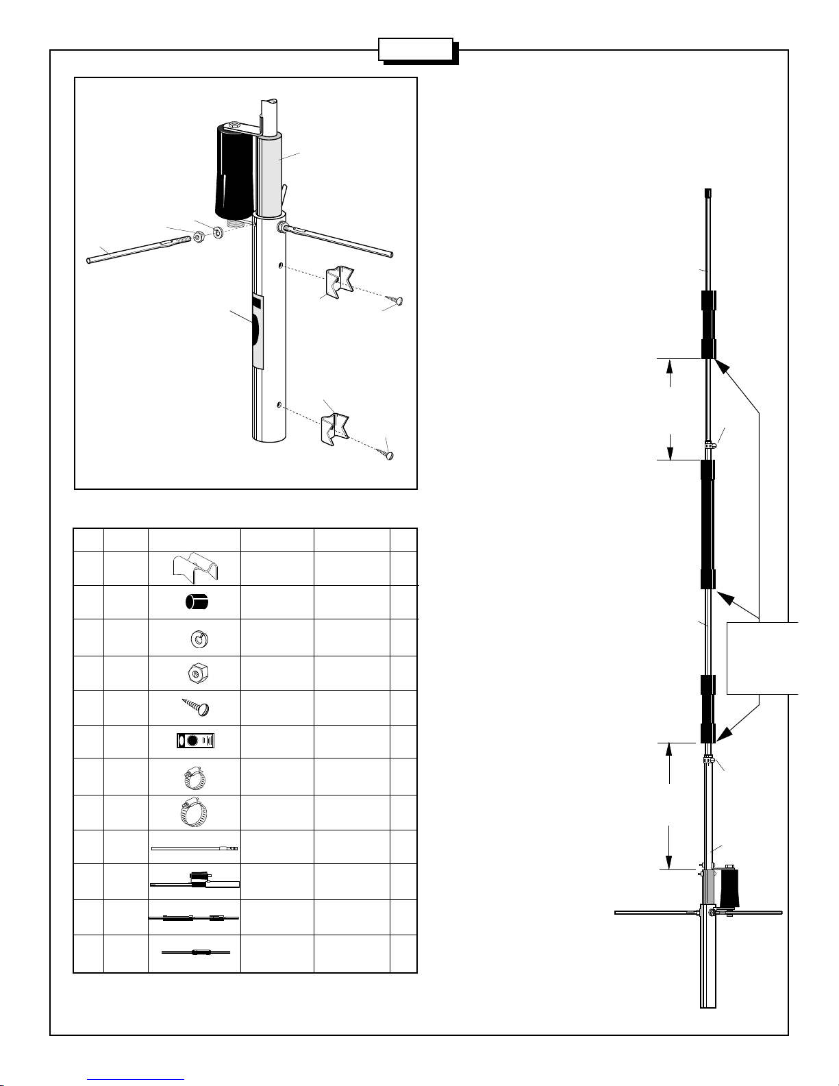
ASSEMBLY
Assembleyourantennabyfollowingthedirectionsandillustrationsinsteps#1through#3. Aftertheantennaiscompletely
assembled, verify the dimensions for accuracy. Return to the section below for final tuning.
TUNING PROCEDURE
With the dimensions shown in figure 2, the antenna should not require any tuning. If you decide to minimize the VSWR
at your favorite operating frequency, insert a good quality 50 Ohm standing wave bridge as close to the antenna as
possible. First check the forward power and then the reverse power. Keep away from the antenna when making these
tests.
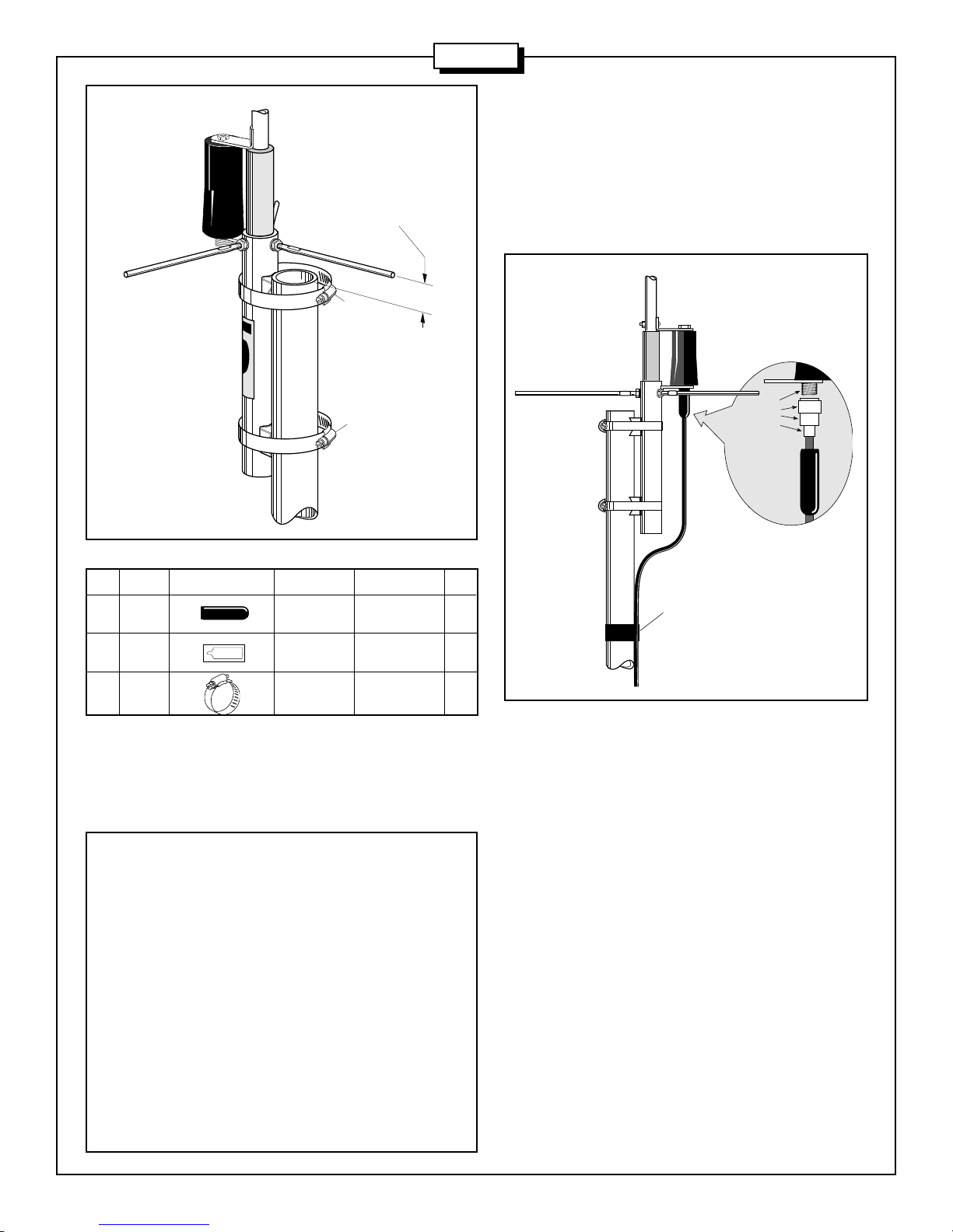
If the VSWR is higher than desired, loosen clamp #409 on the lower section and increase or decrease the length of
dimension "A" by 1/4" (.64 cm). If the VSWR increases, reverse direction. If the VSWR decreased, continue in this
direction until there is little or no reflected power at the bridge. Remember that both frequency bands will be affected by
this adjustment so some compromise may be required.
A VSWR of 1.5:1 meets commercial standards. Even if the VSWR is 2:1 this antenna will still radiate an optimum signal
and meet all specifications.