manuals.online logo
Brands
  1. Home
  2. •
  3. Brands
  4. •
  5. Custom Model Railroads
  6. •
  7. Toy
  8. •
  9. Custom Model Railroads Railroad Headquarters Building Assembly instructions

Custom Model Railroads Railroad Headquarters Building Assembly instructions

1
Railroad Headquarters Building
Instructions for Assembly of the HO scale kit.
v1.1
Kit Contents:
135 ea. laser cut .090" acrylic parts.
69 ea. laser cut .060" acrylic parts.
20 ea. .080" styrene rod.
9 ea. window glass templates
9 ea. window glazing
Instructions with diagrams
Thank you for purchasing this kit. Please read these
instructions completely before beginning and take your
time. Allow parts to dry after painting or gluing and do not
try to build this in one night.
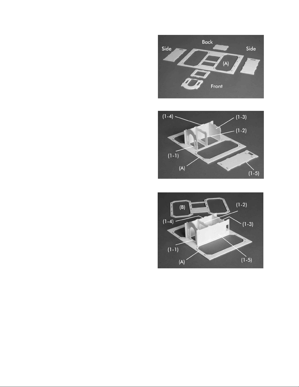
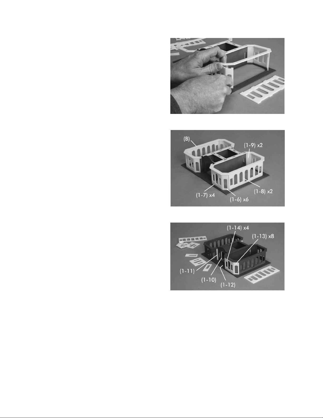
Drawings of all the parts have been included for ease of part identification.
Practice gluing the acrylic together if you have never done it before. There is plenty of scrap in
your kit that you can use for this.
If by chance a part is missing or broken, please write us indicating the kit name and part number
and we will send you a replacement.
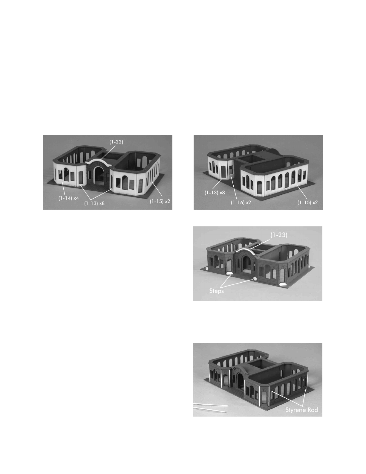
Please note that parts of the kit have been painted gray in the assembly photos so that new parts
can easily be seen and identified. This is only for ease of identifying parts and seeing them
clearly in the photos. We recommend gluing all parts together prior to painting unless otherwise
noted.
Pre-production models were used in these instructions, your parts may vary slightly.
You will need the following items to assemble your model: Hobby knife, fine sand paper, file,
paint (see “Painting Your Model”), paint brushes, glue (see “Gluing Acrylic”), modeling putty.
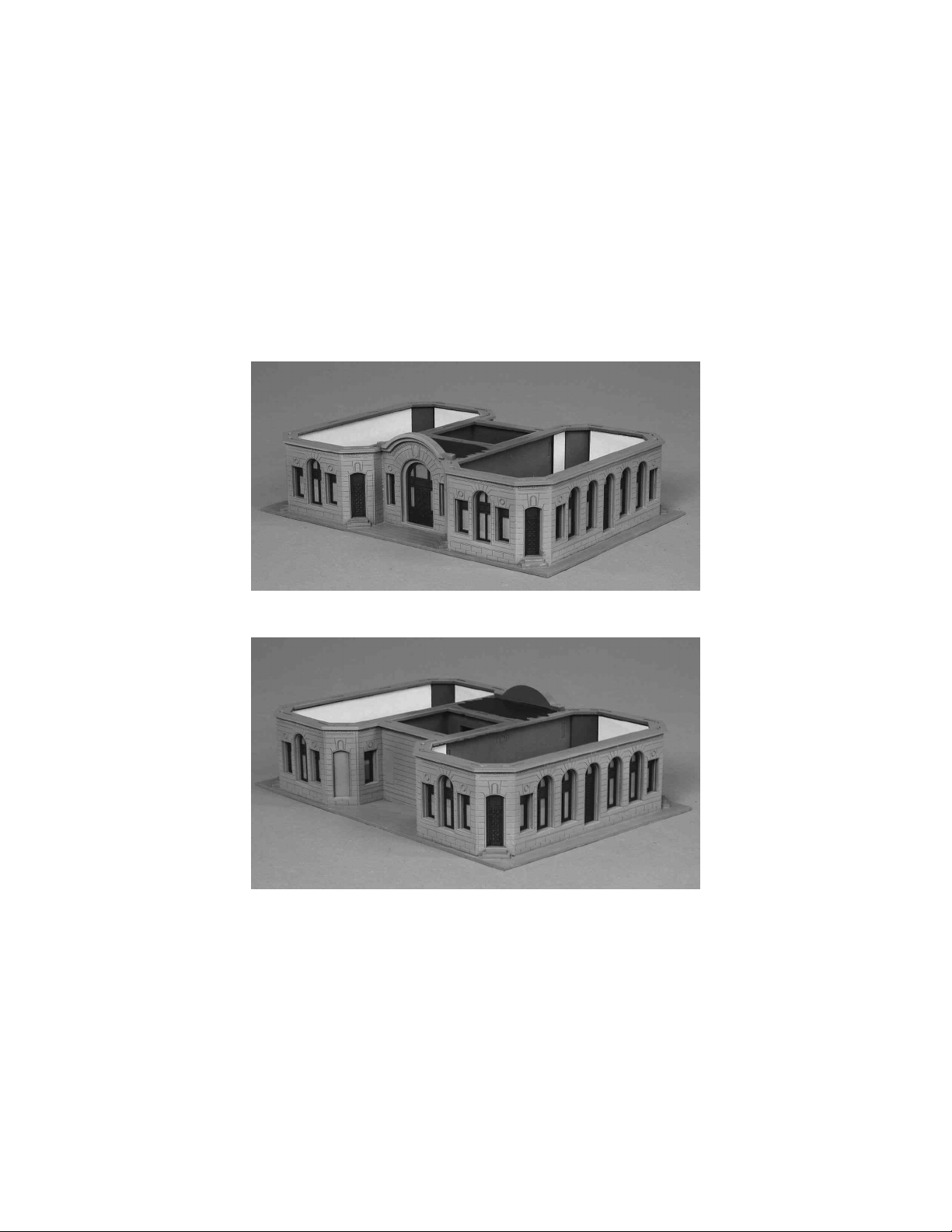
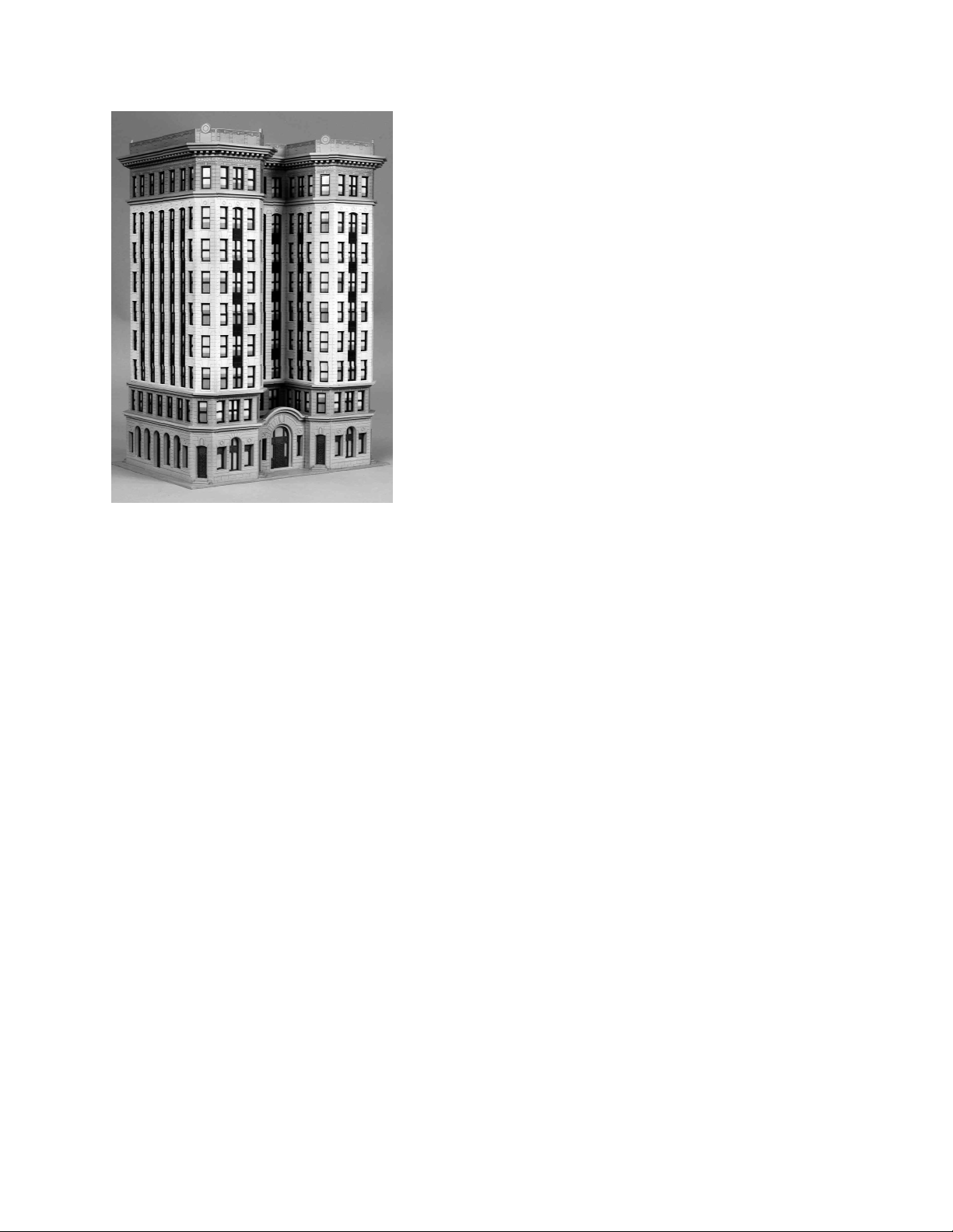
About the Kit
Our kit is based on a thirteen-story high rise built in 1906 to replace its predecessor which was
destroyed by fire. It has a steel frame and stone clad exterior. Inside, it hosts lavish details, a
marble-clad lobby and ornate stairs. When completed, it clearly made a statement as to the
railroad’s confidence moving forward. The building housed railroad headquarters for seventy-
five years. Currently it is a high end hotel. Our model has nine floors and can be increased in
height by the addition of an “Add-On Kit” sold separately.
2
Gluing Acrylic
Always glue acrylic in a well-ventilated area, and read the glue manufacturer’s label for
instructions.
We recommend using Scalecoat brand “Probond”, “Tenax-7R”, Plastruct brand “Bondene
Solvent Cement” or “Plastic Weld Cement”. Most hobby shops carry these products. Or they
may be ordered directly from the manufacturer.
Acrylic must be glued together using a solvent that will melt the two edges and literally fuse
them together. To do this, place the two pieces to be joined together and run a bead of solvent
down the edge. Capillary action will suck the solvent into the joint and after several seconds the
pieces will be fused. After only a few minutes the pieces will be strong enough to work with. The
bond will be completely dry within twenty-four hours using the above-mentioned products.
Solvent can be dispensed two ways.
Typically the solvent comes in a small bottle with a brush in the lid. The brush allows you to
dispense a drop or two of solvent at a time.
You may want to use a polyethylene bottle or syringe with a blunt needle dispenser. This allows
larger amounts of solvent to be dispensed quickly and cleanly. Be sure the bottle you are using is
approved for the solvent you are using or you may melt through it. These bottles may be
purchased from CMR.
Super Glue
Cyanoacrylate (CA) Super Glue
Parts that are not plastic or are painted prior to gluing must be glued together using a non solvent
based glue. This means the parts are held together by the glue and not the process of fusing or
welding them together with solvent. For this we recommend using CA where noted in the
instructions.
Craft Glue
Some parts are easier to glue using craft glue such as “Sobo”. We use craft glue to stick
previously painted parts together when we want a little working time.
3
Preparing Your Model for Painting
We recommend lightly sanding all parts to remove the raised edge created during the laser
cutting process. In order to hide the seams we recommend using “hobbyist putty” such as Green
Squadron modeling putty. Do this in a very well-ventilated area. Apply the putty over the seams
and allow to dry overnight. Once the putty has dried, place a sheet of fine sandpaper on a flat
surface and sand smooth. You may need to apply a second coat of putty and sand again.
This model has 45 degree corners that must be filled. Use the styrene rod to fill the corner gaps
between the front walls. Cut the rod to length. In order to manage the material properly and have
enough we recommend first cutting the long pieces for Unit 3 and then using the remaining
material for the shorter units. You may want to use a brush to apply the glue. The styrene is
much softer than the acrylic and the glue will make it even softer. Allow to dry thoroughly over
night. Sand or file the styrene rods to produce 45 degree corners. Next use a jewelers file to
continue the engraved lines thru each corner. This is a bit tedious but the end results will be
worth it.
See Figure 1.
Note on Tabs
Sometimes it is necessary to sand or file the tabs slightly in order to get them to seat themselves
into the slots. This is due to slight variations in acrylic thickness. If the tabs are not fitting into
the slots properly, you may need to file them back at an angle to fit properly.
Figure 1
4
Painting Your Model
After building each unit we primed our building with Krylon Gray spray paint. We also primed
the window frames. For our building paint scheme, we used acrylic hobby paints which are
available in hobby stores.
We painted the building with two different stone colors. The lower and upper units were painted
with a sandstone color. The shaft (unit 3) was painted very light gray. The building was then
lightly airbrushed with dirt and grime to give it an aged look. The roof was painted black.
Finally we clear coated the building with matte spray to protect the paint finish.
The first floor windows and doors were painted a dark bronze. The upper story windows were
painted black.
Window Glass
There are printed window shades included with your kit. These are designed to be laminated with
acetate window glazing prior to installing in your model. The printed window shades are
numbered to correspond with the window frame parts.
Lightly spray glue the window shade pages on the printed side with spray mount and apply a
sheet of acetate to them. Press in place. We used 3M Spray Mount part number 6065 which is
available at craft and office supply stores. After painting the window frames glue them to the
acetate using super glue (CA).
Place the acetate with the window
frames glued to it face up on a
cutting mat and trim out the frames
and any excess glazing with a
hobby knife. See Figure 2.
It is recommended to lightly spray
the back of the window shade pages
with a sealer such as matte spray or
laquer. This will keep the paper
from buckling due to humidity
changes later.
Figure 2
5
Unit 1
Begin by taking base (A) and laying it flat on your
work surface with the engraved part number facing
up. Insert the tabs of the walls (1-1), (1-2), (1-3),
(1-4) and (1-5) into the slots on part (A) and glue
in place. Be sure the engraved sides of the wall
parts are facing out.
See Figures 3, 4 & 5 for orientation.
While the glue is still soft test fit but DO NOT
GLUE the top (B) onto the assembly with the
engraved part number facing up. Check that all the
tabs are seated properly.
Remove (B) and set aside for later.
See Figure 5.
Figure 3
Figure 4
Figure 5
6
The two building wings are identical but mirrored.
Assemble one side then the other.
Working your way around one wing of the model
one wall at a time, insert the tabs of the walls (1-6),
(1-7), (1-6), (1-8), (1-6), (1-7) and (1-9) into the
slots on part (A) and glue in place. It may help to
have part (B) sitting, DO NOT GLUE, on top of
the assembly while you do this to keep the walls
square. While keeping pressure on the center of
part (B) with your hand you can gently tip or bend
the edge of part (B) up while you insert each new
wall. Allow the glue to set for a few seconds before
moving on the next piece. Be sure part (1-9) is
located in the correct spot at the rear of the
building and that its engraved line is facing out. It
is easy to miss the engraving on this part.
See Figures 6 & 7.
Assemble the other wing in the same manner.
Glue the top (B) onto the assembly with the
engraved part number facing up. Check that all the
tabs are seated properly.
See Figure 7.
Next glue wall (1-10) behind wall (1-1). The part
should be centered on the wall.
See Figure 8.
Glue walls (1-11) and (1-12) on either side of the
entry way. Be sure the decorative engraving is at
the top.
See Figure 8.
Figure 7
Figure 8
Figure 6
7
Working your way around one wing of the model one wall at a time, glue the walls (1-13), (1-
14), (1-13), (1-15), (1-13), (1-14), (1-13) and (1-16) to the assembly. Be sure each wall is
perfectly centered on the wall below it using the window openings as guides. The window
opening in the front wall is just slightly larger than the wall behind it and a slight step back
should be visible. Part (1-16) should be flush at the back corner where it meets part (1-3).
See Figures 9 & 10
Glue the cornice arch (1-22) over the entryway. It should be flush on the top and tuck into the
slots on part (B).
See Figure 9.
Glue the small cornice arch part (1-23) to the face
of part (1-22), they should be flush on the top. You
may want to fill any seams with modelers putty,
allow to dry and sand smooth.
See Figure 11.
Glue two steps in front of each of the six side door
ways as shown.
See Figure 11.
You may want to build the rest of the building units before proceeding with the next step. We
have included the next step here so as to keep the progress in order and show the completion of
one unit before moving on to the next.
See “Preparing Your Model for Painting” for more
detailed information.
Use the .080 styrene rod to fill the corner gaps
between the walls. Allow to dry thoroughly over
night. Sand or file the styrene rods to produce 45
degree corners. Next use a jewelers file to continue
the engraved lines thru each corner.
See Figures 1 & 12.
Figure 9 Figure 10
Figure 11
Figure 12
8
Clean up any imperfections, fill any gaps with modelers putty and sand any rough edges. Wash
the unit with soap and water and allow to dry. Paint Unit 1 as described earlier in the “Painting
Your Model” section of these instructions.
Paint the window frames (1-17), (1-18) x6, (1-19) x4, (1-20) x2 and (1-21) x2 your choice of
color and install the window glazing as described earlier in the “Window Glass” section of these
instructions.
Install the windows in Unit 1 using CA to adhere them to the back of the walls.
See Figures 13 & 14.
Figure 13
Figure 14
9
Unit 2
Take part (C) and lay it flat on your work surface
with the engraved part number facing up. Insert the
tabs of the walls (2-1) x2, (2-2) and (2-3) into the
slots on part (C) and glue in place. Be sure the
engraved sides of the wall parts are facing out and
that the decorative strip is at the top of each part,
See Figures 15.
While the glue is still soft test fit but DO NOT
GLUE the top (D) onto the assembly with the
engraved part number facing up. Check that all the
tabs are seated properly. Remove (D) and set aside
for later.
Working your way around one wing of the model
one wall at a time insert the tabs of the walls (2-4),
(2-5), (2-4), (2-6), (2-4), (2-5) and (2-4) into the
slots on part (C) and glue in place.
See Figure 16.
Assemble the other wing in the same manner.
See Figure 16.
Glue the top (D) onto the assembly with the
engraved part number facing up. Check that all the
tabs are seated properly.
Use the .080 styrene rod to fill the corner gaps
between the walls. Allow to dry thoroughly over
night. Sand or file the styrene rods to produce 45
degree corners. Next use a jewelers file to continue
the engraved lines thru each corner.
See Figure 17.
Figure 15
Figure 16
Figure 17
10
Clean up any imperfections, fill any gaps with modelers putty and sand any rough edges. Wash
the unit with soap and water and allow to dry. Paint Unit 2 as described earlier in the “Painting
Your Model” section of these instructions.
Paint the window frames (2-7) x2, (2-8), (2-9), (2-10) x8, (2-11) x4 and (2-12) x2 your choice of
color and install the window glazing as described earlier in the “Window Glass” section of these
instructions.
Install the windows in Unit 2 using CA to adhere them to the back of the walls.
See Figures 18 & 19.
Figure 18
Figure 19
11
Unit 3
Take part (E) and lay it flat on your work surface
with the engraved part number facing up. Insert the
tabs of the walls (3-1) x2, (3-2) and (3-3) into the
slots on part (E) and glue in place. Be sure the
engraved sides of the wall parts are facing out and
that the arched openings are at the top.
See Figure 20.
While the glue is still soft test fit but DO NOT
GLUE the top (F) onto the assembly with the
engraved part number facing up. Check that all the
tabs are seated properly. Remove (F) and set aside
for later.
Working your way around one wing of the model
one wall at a time, insert the tabs of the walls (3-4),
(3-5), (3-4), (3-6), (3-4), (3-5) and (3-4) into the
slots on part (E) and glue in place.
See Figure 21.
Assemble the other wing in the same manner.
See Figure 21.
Glue the top (F) onto the assembly with the
engraved part number facing up. Check that all the
tabs are seated properly.
Use the .080 styrene rod to fill the corner gaps
between the walls. Allow to dry thoroughly over
night. Sand or file the styrene rods to produce 45
degree corners. Next use a jewelers file to continue
the engraved lines thru each corner.
See Figure 22.
Figure 20
Figure 21
Figure 22
12
Clean up any imperfections, fill any gaps with modelers putty and sand any rough edges. Wash
the unit with soap and water and allow to dry. Paint Unit 3 as described earlier in the “Painting
Your Model” section of these instructions.
Paint the window frames (3-7) x2, (3-8), (3-9), (3-10) x8, (3-11) x4 and (3-12) x2 your choice of
color and install the window glazing as described earlier in the “Window Glass” section of these
instructions.
Install the windows in Unit 3 using CA to adhere them to the back of the walls.
See Figures 23 & 24.
Figure 23
Figure 24
13
Unit 4
Take part (G) and lay it flat on your work surface
with the engraved part number facing up. Insert the
tabs of the walls (4-1) x2, (4-2) and (4-3) into the
slots on part (G) and glue in place. Be sure the
engraved sides of the wall parts are facing out and
that the decorative strip is at the top.
See Figure 25.
While the glue is still soft test fit but DO NOT
GLUE the top (H) onto the assembly with the
engraved part number facing up. Check that all the
tabs are seated properly. Remove (H) and set aside
for later.
Working your way around one wing of the model
one wall at a time insert the tabs of the walls (4-4),
(4-5), (4-4), (4-6), (4-4), (4-5) and (4-4) into the
slots on part (G) and glue in place.
See Figure 26.
Assemble the other wing in the same manner.
See Figure 26.
Glue the top (H) onto the assembly with the
engraved part number facing up. Check that all the
tabs are seated properly.
Use the .080 styrene rod to fill the corner gaps
between the walls. Allow to dry thoroughly over
night. Sand or file the styrene rods to produce 45
degree corners. Next use a jewelers file to continue
the engraved lines thru each corner.
See Figure 27.
Figure 25
Figure 26
Figure 27
14
Clean up any imperfections, fill any gaps with modelers putty and sand any rough edges. Wash
the unit with soap and water and allow to dry. Paint Unit 4 as described earlier in the “Painting
Your Model” section of these instructions.
Paint the window frames (4-7) x2, (4-8), (4-9), (4-10) x8, (4-11) x4 and (4-12) x2 your choice of
color and install the window glazing as described earlier in the “Window Glass” section of these
instructions.
Install the windows in Unit 4 using CA to adhere them to the back of the walls.
See Figures 28 & 29.
Figure 28
Figure 29
15
Unit 5
To build the roof, place part (L) with the number
facing up on your work surface. Glue part (K) to it
with the engraved number facing down. Make sure
the parts are perfectly centered. Next glue part (J)
to part (K) with the engraved number facing down.
Use the center holes in the parts for alignment.
Finally glue Part (I) to (J) with the engraved
number facing down.
See Figure 30.
To build the parapet wall around the roof begin in
the center. Make sure the engraved side of each
part is always facing out. Insert the tabs of wall
(5-1) in the center slots at the front of the building.
Next glue walls (5-2) and (5-3) into the slots on
either side of part (5-1). The parts should overlap
the ends of part (5-1) and form a nice square
corner.
Do the same at the back of the building with part
(5-1) in the center sandwiched between parts (5-4)
and (5-5).
See Figure 31.
Working your way around one wing of the model
one wall at a time insert the tabs of the walls (5-6),
(5-7), (5-6), (5-8), (5-6), (5-7) and (5-6) into the
slots on part (L) and glue in place.
See Figure 32.
Assemble the other wing in the same manner.
See Figure 32.
Figure 30
Figure 31
Figure 32
16
Use the .080 styrene rod to fill the corner gaps
between the walls. Allow to dry thoroughly over
night. Sand or file the styrene rods to produce 45
degree corners. Next use a jewelers file to continue
the engraved lines thru each corner.
See Figure 33.
Clean up any imperfections, fill any gaps with
modelers putty and sand any rough edges. Glue the
roof hatch (5-9) to the top of the roof. If you
accidentally placed part (L) upside down and the engraved letter is showing you can cover it with
the roof hatch. Wash the unit with soap and water and allow to dry. Paint Unit 5 as described
earlier in the “Painting Your Model” section of these instructions.
See Figure 34.
Figure 33
Figure 34
17
Final Assembly
Now that you have built all of the building units, it is time to assemble them. Make sure that the
bottom and top of each unit is perfectly flat and smooth. Sand or file any imperfections off as
necessary.
Glue the units together one at a time and allow to dry before proceeding to the next unit. You can
run a bead of glue along the cornice where the two pieces meet. The interior rectangular openings
should align from one unit to the next. Continue gluing the units together in this fashion making
sure that everything is straight and true as you go along.
Once completed touch up any glue and paint imperfections along the cornices.
Your building is finished and ready to install on your layout. You may add roof details, awnings,
lights and other details. We thank you for purchasing this kit from CMR and hope that you have
enjoyed building it. Be sure to see our other kits at www.cmrtrain.com.
18
19
BA
Railroad Headquarters
Unit 1
Parts HO Page 1
(1-1)
(A) (B)
(1-2) (1-3) (1-4) (1-5)
(1-6) x6 (1-7) x4 (1-8) x2 (1-9) x2 (1-10)
(1-16) x2
(1-17) (1-18) x6 (1-19) x4 (1-20) x2 (1-21) x2
(1-22)
Steps X4
(1-23)
(1-13) x8 (1-14) x4 (1-15) x2(1-11) (1-12)

Popular Toy manuals by other brands

Meccano 17202 instructions

Meccano

Meccano 17202 instructions

Premier Kites Tri-Odessey Assembly instructions

Premier Kites

Premier Kites Tri-Odessey Assembly instructions

marklin 5965 user manual

marklin

marklin 5965 user manual

Philips SCD940 Specifications

Philips

Philips SCD940 Specifications

marklin BR 288 002 manual

marklin

marklin BR 288 002 manual

Radio Shack Mercedez-Benz CLK DTM 2000 owner's manual

Radio Shack

Radio Shack Mercedez-Benz CLK DTM 2000 owner's manual

Fisher-Price 73409 instructions

Fisher-Price

Fisher-Price 73409 instructions

Reely ICE LAND Service manual

Reely

Reely ICE LAND Service manual

Kid Trax Toys Audi TT owner's manual

Kid Trax Toys

Kid Trax Toys Audi TT owner's manual

Serpent Seven20 instruction manual

Serpent

Serpent Seven20 instruction manual

Eduard 32 876 manual

Eduard

Eduard 32 876 manual

Fisher-Price N1416 instruction sheet

Fisher-Price

Fisher-Price N1416 instruction sheet

Eduard Fw 190A-5 Weekend manual

Eduard

Eduard Fw 190A-5 Weekend manual

Lean Cars CH9959 Installation and operation manual

Lean Cars

Lean Cars CH9959 Installation and operation manual

Radikal E640 manual

Radikal

Radikal E640 manual

Kyosho stratus 1600 v-tail instruction manual

Kyosho

Kyosho stratus 1600 v-tail instruction manual

Fisher-Price POWER WHEELS ARCTIC CAT CGY61 owner's manual

Fisher-Price

Fisher-Price POWER WHEELS ARCTIC CAT CGY61 owner's manual

E-FLITE Mini Pulse XT PNP Assembly manual

E-FLITE

E-FLITE Mini Pulse XT PNP Assembly manual

manuals.online logo
manuals.online logoBrands
  • About & Mission
  • Contact us
  • Privacy Policy
  • Terms and Conditions

Copyright 2025 Manuals.Online. All Rights Reserved.