Cuttermasters Professional JXT User manual

CuttermastersCuttermastersCuttermasters
The CUTTERMASTER Professional
Tool Grinder, JXT
Operator’s Manual
Rev. 2020/10/19

www.cuttermasters.com - Toll Free (800) 417 2171
CUTTERMASTER Professional JXT User’s Manual
Page 2
Table of Contents
Chapter 1 The CUTTERMASTER Professional Journeyman JXT
1.1 Introduction, Forward, Contact Information .......................... 3
1.2 Disclaimer and Health Warning: Dust................................... 4
1.3 JourneymanJXTSpecications,OverviewandTheory ....... 5
1.4 Set Up and Care for Your JXT.............................................. 7
1.5 Grinding Wheels: Basics ...................................................... 9
1.6 Grinding Wheels: Truing and Dressing............................... 10
Chapter 2 End Mill Grinding: The Basics Before you Start
2.1 EndMillDenitions,TypesofRelief,TestTools ..................11
2.2 Organizing Your Grinding Project ....................................... 13
Chapter 3 End Mill Grinding Operations
3.0 General Check Before Use................................................. 16
3.1 Flute Outside Diameter Grinding........................................ 17
3.2 End Grinding Using 11V9C Wheel Outside Diameter ........ 18
3.3 End Grinding Using 11V9C Wheel Face - Left ................... 20
3.4 End Grinding Using 11V9C Wheel Face - Right................. 20
3.4 End Gashing....................................................................... 20
Appendix 1 End Mill Sharpening Guide, Wheel Types ................................ 22
2 Base Exploded View................................................................. 23
3 Motor Tower Diagram................................................................ 24
4 Air Bearing Exploded View........................................................ 25

www.cuttermasters.com - Toll Free (800) 417 2171
CUTTERMASTER Professional JXT User’s Manual
Page 3
Copyright 2020
This document may not be reproduced in whole or in part without the express written permission of
Toycen Industries
Cuttermasters
2353 Ridgecrest Place
Ottawa ON K1H7V4
Canada
(800) 417-2171
Toycen Corporation
808 Proctor Avenue
Ogdensburg NY 13669
U.S.A
(800) 417-2171
Chapter 1: Introduction to the CUTTERMASTER
Professional Journeyman, JXT
Congratulations on purchasing your CUTTERMASTER Professional Tool Grinder, JXT.
The CUTTERMASTER has been the best name in bench top end mill sharpeners since 1972 and
that tradition of quality continues with the new CUTTERMASTER Professional line up. The JXT has
been designed with new features to meet the demands of today’s prototype and production shops
andprovidessuperiorexibilityandeaseofusefortoolregrindingandtoolmodications.
With the JXT you will be able to grind the diameters and ends of standard end mills in one easy
setup. With nine working axes you will also be able to sharpen roughing end mills, reamers (circum-
ferential lands), end gashes, side and face cutters, annular drills, and countersinks. You will be able
togrindreducednecks,cylindergrindsmallrounds,grindWeldonats,andcut-ocarbideorhigh
speed steel tools.
This revolutionary product was designed and built in our own shop.
Forward
Contact Info
If you have any service or parts requests, or questions about this manual, please feel free to call or
write to us at

www.cuttermasters.com - Toll Free (800) 417 2171
CUTTERMASTER Professional JXT User’s Manual
Page 4
1.2 Disclaimer
The CUTTERMASTER Professional is a machine tool and as such is heavy and has large moving
parts and grinding wheels rotating at high speed. These wheels are dangerous and they emit dust,
carbide and steel fragments during the normal course of operation which are harmful if inhaled or
come into contact with skin or eyes. The manufacturer is not responsible for any injury or death
caused by this apparatus.
Upon delivery the owner of the machine assumes full responsibility for itool spindle safe operation.
Care must be taken to observe proper industrial safety precautions. Always wear suitable breathing
and eye protection when using the CUTTERMASTER Professional or any other grinding machine.
Motor: 400 Watt DC Reversing and Variable Speed
Warranty: Two Year on Motor and Control
Net weight: 31 Pounds
Dimensions 18 high 6 wide 8 depth (single)
Health Warning: Dust
Tool grinding and grinding in general produces dust that is hazardous to your health and may con-
tain heavy metals. We strongly urge that you consider a dust exhaust system. You are responsible
for taking the proper precautions and/or utilizing the proper auxiliary exhaust systems to protect your
health and that of your employees.
Toycen Industries, by this advisement waives any and all responsibility for any real or alleged claims
of health damage as the result of using their equipment(s) without heed to this warning.

www.cuttermasters.com - Toll Free (800) 417 2171
CUTTERMASTER Professional JXT User’s Manual
Page 5
1.3 Journeyman JXT Specications
Air Bearing Stroke 10.5″(266.7mm)
Air Bearing Swing Over Table 9.8″(248.92)
Cutting Tool Capacity 2″shank,9.8″O.D.
Flute Length 10.5″
T-Slot Dimensions 0.8″(20.32mm)x0.5″(12.7mm)x0.67″(17.018mm)
Table Feed Graduations 0.001″(0.02mm)
x-Axis Table Travel 6″(152.4mm)
y-Axis Table Travel 3″(76.2mm)+(76.2mm)
z-Axis Table Travel 3” (76.2mm) from 3.3 to 6.3 inch
x-Axis Table Working Space 16.5″(419.1mm)x5.5″(139.7mm)
y-Axis Table Working Space 3” (76.2mm) from 3.3 to 6.3 inch
Wheel Mount Standard1.25″bore3,4,5.6″cupordishwheel
Motor / Tilt 1/3hp,3450rpmVariableSpeed/InniteTiltAxis
Mount
Control with Torque Compensation Toycen Whisper Drive Input 120/240 AC 60/50 Hz
Output 130-20 V DC
Net Weight 210 lbs (98 Kg)
Gross Weight 232lb (106Kg)
Machine Dimensions Excluding Handwheels 21″x20″x21″
Note: This grinder plugs in to regular household AC current and converts to DC onboard.
1.3 Journeyman JXT Specications

www.cuttermasters.com - Toll Free (800) 417 2171
CUTTERMASTER Professional JXT User’s Manual
Page 6
1.3 Journeyman JXT Diagram
1. z-Axis Motor Lift Hand Wheel
2. Motor Lift Lever
3. Stylus
4. Indexing Collar
5. Front Collar
6. y-Axis Table Hand Wheel
7. x-Axis Table Hand Wheel
8. Air Spindle Pivot Base
9. Draw Tube
10. Quill, Spindle
2 - (behind)
9
8
7
6
54
3
1
10

www.cuttermasters.com - Toll Free (800) 417 2171
CUTTERMASTER Professional JXT User’s Manual
Page 7
1
1
2
2
3
3
4
4
A A
B
B
C
C
D
D
SHEET 1 OF 1
DRAWN
CHECKED
APPROVED
Jeff
DWG NAME
2020 SINGLE UTS Front Side
TITLE
Cuttermaster Professional DC Tower
SIZE
C
REV
3
Toycen
This document is the property of Toycen and cannot be copied or reproduced in full or in
part or communicated to third parties without specific written permission from Toycen.
UNLESS OTHERWISE SPECIFIED:
DRAWINGS ARE IN INCHES (mm).
DATE
SCALE:
LINEAR TOLERANCES ANGLES ARE:
ARE: .X = ±.03 X = ±0.5°
.XX = ±.01 .X = ±0.1°
.XXX = ±.005
SURFACE FINISH:
DO NOT SCALE DRAWING
125 THIRD ANGLE
10-32 WHeel Cap Bolts
Operation Gib Clamp thumb screws
90 Degree Spring ball
Up 22 Down 7 Motor Tilt lock
Remove this to tilt the motor into the 890 degree Position
End grinds withnthe face of the wheel
Multi Position Wheel guards in 5 and 6 inch
Gib tension set screws(3)
Motor Tilt Rotate
Tension Setting
Motor Vertical Lift
Indexing Handle
Acme 10 Lead screw with backlash
and rotational tension adjustment
Table Clamp bolt 3/8-16
Vertical Travel Hand Dial
Standard 1-1/4 Tool Grinder wheel hub
Oillite Bushed Motor tilt with
Ratchet Lever angle Locks
Notes:Vertical Slide assembly gib must be
tensioned so the it is tight but free to travel ,dove tail assemblies are lapped
and should travel freely when adjusted.
Minor deflections are normal Tighten thumb screwswhile in use for the best
grinding finishes
Whenyou’reindexingtothenextutebetweengrinds,
the tool needs to be clear of the grinding wheel. To
do so, you have the choice of rocking the air spindle
towards you, or using the Motor Vertical Lift Indexing
Handle. When using the motor lift handle, if you notice
that the motor isn’t returning consistently, try tightening
the backlash compensation screw.
z-Axis Backlash Compensator:

www.cuttermasters.com - Toll Free (800) 417 2171
CUTTERMASTER Professional JXT User’s Manual
Page 8
CUTTERMASTER Professional Products have been designed to accommodate a variety of needs.
This system has been designed to be easy to use and maintain. As with all machine tools care must
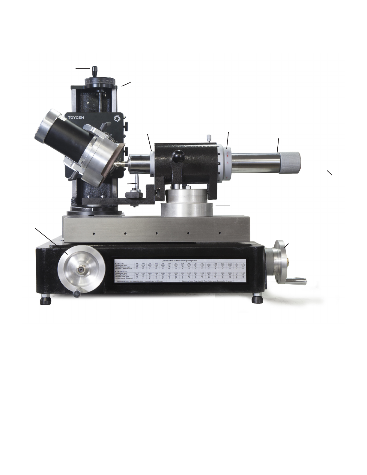
be taken to keep all working surfaces clean and in good repair. There are 5 movements to your
CUTTERMASTER Professional DC tower
• Up and down using Top dial lead screw
• Motor Tilt
• Motor Tip
• Base pivot
• VerticalIndexingwiththehandle(forquickliftoutofutes,Cornerrads)
The DC Motor comes with a single or twin spindle so motor/spindle assembly spindle to positive and
negative angles and rotates 360°. Cutting tool clearance angles can be tensioned so as to be quickly
adjusted as needed providing real angle result when setting angles without the use of tools.
Thereareninedierentaxestoworkwithforunlimitedversatility.YourJXSgrindsO.D.sandendsof
standardendmillsinonesetupwithinafewminutes.YoucansharpenendmilluteI.D.s,uteO.D.s
and ends (primary and secondary), as well as roughing end mills, carbide tools, reamers, end gash-
es,smallroundsorreamers(circumferentiallands),reducedneckgrinds,Weldonats,Carbideand
HSSCutos.
Most grinders have a single speed AC motor, designed to be inexpensive for the manufacturers to
produce. This is not conducive to a good tool grinding environment where conditions vary from tool to
tool. DC motors have more torque throughout their variable range of speeds allowing for deeper cuts
without heat damage to the tool, given that it is a dry grinding environment. The twin wheel head of
theJXSDCTowercanbeipped,reversedandspeedadjustedtosuitmostanygrindingrequire-
ment.
Ourgrindingwheelshavebeenspecicallydesignedfordrygrindingandgoodbalance.Onceyou
get your wheels dialed in, you can work from wheel to wheel without having to re-mount and dial in as
frequently.
The Toycen Radius Air Bearing has a 180° swivel base for radius grinding and takes standard 5C
collets with end mill holders available that can hold shank sizes up to 2”. The Toycen Motor Tower
provides easy and accurate positioning of the wheels to the tool being ground and allows two wheels
to be set and trued allowing for the indexing of one wheel to the next which is intended to reduce set
up times.
Journeyman JXT Overview and Theory

www.cuttermasters.com - Toll Free (800) 417 2171
CUTTERMASTER Professional JXT User’s Manual
Page 9
1.4 Set Up and Care for Your JXT
Themachineshouldbekeptfreeofdustanddebrisandwhennotinusealightlmofoil(e.g.Oiland
WD-40 mix) should be applied to unprotected metal surfaces.
The assemblies are all cast iron and steel sliding surfaces and threads should be kept clean and
dry:aperiodiccleaningbysprayingwithWD-40andblownowithcompressedairwillkeepthelead
screws in good service. Gibs should be free of dirt and slide freely.
The Base and Motor Tower: The CUTTERMASTER Professional JX has been designed using the
proven Cuttermaster base, the system is stable and allows for the use of magnetic base indicators in
virtually any position. There is no guessing when dialing-in any feed or position move. Being made
fromamonolithiccastbaseandmotortower,theJXSabsorbsvibration.Havingsignicantmassalso
meansthatifadjustmentsare“snug”,motorrotationandtowerpivotcanbeusedwithoutsignicant
tightening. Note: Always check all wheel mounts, angular and rotational adjusts for suitable
tightness prior performing a grinding operation.
Choose a good, stable and quiet location (The CUTTERMASTER Professional is very quiet) for the
machine. We recommend our CM-10S Cabinet Base if one is needed. Level the machine using a lev-
elonthewaysandnetunewiththeadjustablefeet.
Wipeanyoilooftheways.Theyshouldbeclean
and dry for operation. They may be wiped down from
time to time with a WD-40 and oil mix to prevent rust.
During normal operation care should be taken to
keep the carriages and leadscrews clean and free
from dust and can be done with compressed air. The
lead screws are black oxide 4140 steel with steel
drive nuts. The carriage drive nuts can be easily re-
placed should they wear over time.
A light colored back drop helps the operator locate
the grinding wheel as it approaches the tool and also
protects the ways.
CM-10S Cabinet Base

www.cuttermasters.com - Toll Free (800) 417 2171
CUTTERMASTER Professional JXT User’s Manual
Page 10
The DC Variable Speed Motor and Control is reversible, variable speed and produces ten times
the torque than the standard 1/3HP AC motor . This helps eliminate tool burning by facilitating heavy.
Cuts at greatly reduced RPM, cutting grinding times in half on some tools. Read the appendix KB
Control Board Manual before operating. The internal circuit board trim pots have been set according
to our preferences.
The CM-02A Air Spindle:
Note: Always have air supplied to the air spindle when being moved or in use. Check the air spindle
components and wipe them completely free from dust and oil using acetone or a solvent that does not
leave a residue (See Cleaning Section).
Hook up shop air to the air spindle. There must be clean dry air present (must have an air dryer on
theline)itcanbeusedwithoutadditionalltrationandmoisturecontrol.
Theairspindleusesonetotwocfmat80to100psi.Aregulatorltermayhaveshippedwiththema-
chine(CM-01P,CM-02Rdoesnotmountalterbutitcanbemountednearthemachineifrequired).
ThelterassemblyisnotattachedtotheCM-02Rairspindlebecausethereareadjustmentdevices
that need to be accessed and the spindle must be free to more.
The height of the stylus that the end mill rides on should be kept to the same height as the center line
of the air bearing spindle. Using a 3/8 5C collet mount the 3/8 Half Pin in the air bearing to set the sty-
lus height. The face points down, parallel with the x table top face. Raise the stylus to touch the face
ofthecenternderandlockthenutatthestylusbase.

www.cuttermasters.com - Toll Free (800) 417 2171
CUTTERMASTER Professional JXT User’s Manual
Page 11
1.5 Grinding Wheels
The Machine has been designed for a variety of wheels and wheel
mounts.Withthemachinethereareseveralspacerstotthe1.25”
hubs. These are to be used to space the wheels out to best ac-
commodate reach and adjust wheel approach. Most of our wheels
are available in CBN (for High Speed Steel Tools) and diamond
(for carbide tools).
Typical Wheels used are 1A1 and Taper Cup and Flared Cup
11V9C.Wealsohavespecialtywheelsforsetscrewats,rough-
ers,cuto,rads,necksandmore.oralistofourrecommended
industrial grinding wheels or to contact us about grinding wheels
visit
https://cuttermasters.com/product-category/grinding-wheels/
The variable speed high torque motor allows for much deeper cuts
can be accomplished while minimizing heat. We have designed
wheelsspecicallyforthispurpose.Alwaysusegoodwheelsand
inspect them before each use.
Flared Cup Wheel
11V9C
Flared Cup 11V9C
Shoulder/Neck 1A1
Micro Neck
ProledRadius
Fluting
CutO
Face
Chamfer
Annular Cutter
Ends P P
Flutes (O.D.) P
End Gash P P
Corner Rad (Bull and Ball) P
Gumming Inside Flutes P P P
Neck Reduction P P P P
Micro Neck Reduction P P P
Weldon Set Screw Flats P
T-Cutter P
Reamers P P P P
Countersinks P
Taps P P
Drills P
Annular Cutters P
Chamfer Mills P
Corner Prep P
CarbideCutO P
Grinding Wheel Type
Grinding Operation
Table: Recommended Grinding Wheel Type by Operation
Chamfer Wheel
Shoulder Wheel
1A1
Face Wheel
Common Wheel Types
Available in various sizes and
CBN and Diamond

www.cuttermasters.com - Toll Free (800) 417 2171
CUTTERMASTER Professional JXT User’s Manual
Page 12
1.6 Grinding Wheel Truing & Dressing
Wheel Truing Device
Spindle Mounted (Hand Held Available)
Wheels must always be dialed in and prepped.
The tool spindle hubs have less than .0005” run out --- we are at the mercy of the motor manufactur-
ers,thereforethebestnishisalwaysgoingtobefromawheelthathasjustbeentruedinplace.
Upon completion of the mechanical truing process (run out), a brake truing device, single point dia-
mond dresser, diamond nib, metal bonded wheel, or rotary diamond dresser will be used to complete
the trueing process for all bonds except plated. With one of the aforementioned devices, true until
you have achieved a reading on the indicator of 0.0005 inches. The abrasive and the bond type are
the most important criteria for deciding the type of trueing and/or dressing system to use. For trueing
only with a point contact, never in-feed more than 0.0005” (0.013mm) per pass for super abrasives
(CBN or Diamond), or more than 0.0015” (0.04mm) per pass for conventional abrasives.
We recommend our CM-WT Spindle Mounted Truing
Device to true our resin bond cup wheels. The CM-WT
is a very easy to set up abrasive wheel system and a
simpler solution to truing your bonded wheels. This
dynamically braked abrasive truing wheel is specially
formulated for grinding CBN and diamond resin bond
wheels into true. It is designed to be used with tool
grinders where it is convenient to hold the truing as-
sembly in a collet or chuck. It is available with a handle
for hand held truing. The CM-WT is more complicated
than it looks, it has three bearings in it and a 10,000
RPM Desmond wheel that will do a great job bringing
yourwheelintotrue.Mountitinthecolletandbringitpastthewheelinsuchawaythatitcanscuit
into true. The nylock nut should be adjusted so that there is light resistance (ie. the wheel wont rotate
freely).
Conventional abrasives (aluminum
oxide and silicon carbide) can be trued
and dressed at the same time, using a
single point dresser. The conventional
abrasive is quite friable (friability = ease
with which an abrasive fractures). This
means a quality diamond with a carat
size appropriate for the diameter of the
wheel, thickness of the wheel and abra-
sive grain size should be used.
Dressing: Once the wheel has been
trued, dressing brings the grit media
proud above the resin substrate. Use
an Aluminum Oxide dressing stick for
resin bond wheels. Use a Silicon car-
bidedressingstickforvitriedwheels.

www.cuttermasters.com - Toll Free (800) 417 2171
CUTTERMASTER Professional JXT User’s Manual
Page 13
Chapter 2: End Mill Grinding - The Basics Before you
Start
2.1 End Mill Denition
Endmillsareprolesharpmillingcutters.Assuch,theyrequirecertaintreatmentwhensharpening.
These tools have a relatively small diameter in proportion to their length. Because of this long shape,
careshouldbetakenwhenholdingtoeliminatechatter,improvenishpropertiesandallowforgood
tool uniformity on the diameter. These tools also have a relatively small mass, meaning that care
should be taken by monitoring heat generated during the grinding process.
If the end mill has centers, these can be used for concentric holding. If not, the tool is generally held
byacolletattheshankendwithatoothrestsetinaspecicrelationtothewheelandtoolcenter.
This tooth/tool rest is usually placed directly at the point of contact between the wheel and the cutter,
minimizing vibration during the grinding process.
4-Flute Center Cutting End MIll

www.cuttermasters.com - Toll Free (800) 417 2171
CUTTERMASTER Professional JXT User’s Manual
Page 14
Types of Relief
Endmillscanbesharpenedwiththreedierenttypesofreliefonthediameter:
1. aconcave,almostatsurfaceisproducedwiththefaceofaplainwheel;
2. aatreliefsurfaceisproducedwithacupwheel.
3. a radial or eccentric relief is produced by presenting the face of a plain wheel at an
angletothecuttingaxisofahelical-utedendmillorbydressinganangleontheface
of a wheel rotating on a parallel axis.
Eccentricreliefproducesarelativelynecuttingedgefreefromminutenicksandasaresultisstron-
gerthanthoseproducedbyothermethods.Anotherbenetofthismethodofre-grindingisthata
secondary clearance is not needed. If the grinding wheel face width is maintained so that it is wider
than the relieved land (measured in an axial direction), wide primary lands are possible without dan-
geroftheheelofthelandcontactingthenishedsurfaceproducedwhentheendmilliscutting.This
is due to the fact that the clearance angle formed by the curve or angle on the wheel increases as it
progresses further from the cutting edge. Most manufacturers, however, consider it good practice to
provide a secondary clearance on end mill teeth, except on the smallest size of cutters.
Onecautiontobeobservedifsingleclearanceisused,isthataverylightnishinggrindmustbe
takenbecauseofthelongerlineofcontactbetweenthewheelandtheendmill.Heavynishingcuts
inviteburning,causeaccuracytobesacricedandcancausethediametertobereducedmorethan
necessary.
Test Tools
A grinding project is like all other operations in a machine shop, in that it may be unadvisable to take
trialcutsonanishproduct.Forthisreasonitisgoodtohavesetuportestcuttingtoolskeptaside
totestanglesandnishespriortogrindingthenalproduct.

www.cuttermasters.com - Toll Free (800) 417 2171
CUTTERMASTER Professional JXT User’s Manual
Page 15
2.2 Organizing Your Grinding Project
1. Determine and separate the HSS tools from the carbide tools. Aluminum Oxide (Al2O3) wheels will
disintegrate if you try to sharpen carbide tools with them and, conversely, diamond wheels will plug up
if used to sharpen high speed steel.
2. CBN wheels can be used to excellent advantage on HSS tools, providing 50 to 100 times the life
at 10 times the cost of Al2O3.CBNalsoproducesbetternishesandhigheraccuracythanAl2O3be-
cause the abrasive and bond/backing materials are thermally conductive, absorbing and dissipating
much of the heat produced.
3. Once you have separated the tools, install the correct wheel for the material you are going to
sharpenonthemachine.Generally,onewillhavebetterresultsusingthenergritwheelsandlighter
cuts, versus coarser wheels and heavier cuts.
4. Organize the grinding project by separating the tools into groups by size and condition of the tool.
The tools requiring the most work should be left to last as they require more severe cutting action and
avarietyofoperationssuchasendgashingorotheradditionalendproling.
5. Sharpening tools that require heavy work involves additional setups. It is advisable to consolidate
these setups based on similarity. This method helps produce more uniform results through the job,
reduces operator fatigue from repetitive setup and setup error.
• If the end is broken and needs to be repaired, this is a special project. It is probably best
toleavethesecutterstothelast,astheyshouldbecutowithacutowheelandthen
recongured.
• From a time point of view, be selective about which tools to repair, because it requires
keenskillsandtheuseofdierentwheelssuchasacut-owheelortheuseofawheel
suchasa12V9or1A1toproducetheclearanceprole(gash)ontheend.
If the cutter has been too badly abused you will not be able to bring it to a satisfactory state by
re-grinding. Overuse or allowing a cutter to become too dull before re-sharpening can fatigue the
cutter material itself, as well as ruin the geometry. In this case, talk to your supervisor or the owner
of the cutter before attempting to sharpen the tool. The best option might be to just return it to the
person who ruined it, as is.
Edges, Material and Proles
The main work piece material consideration when sharpening an end mill is the relief angle at and
behind the cutting edge. The exact type of relief is generally unimportant in most cases. Harder ma-
terials require the use of a smaller relief angle, so the cutting edge has enough thickness and support
to withstand the higher cutting forces and greater heat generated during cutting.
Inhardermaterials,edgesshouldbehonedtosuittheapplication.Ahoneservestoreneandrein-
force the edge, allowing for a more uniform distribution of the stresses that break down the material
beginning at the moments of highest stress over time.
Every material has an endurance limit. When a carbide cutter is too “fatigued” it will show in chipping
andakingatthecuttingedges.Thiswillbemoreapparentinthehardermaterialssuchascarbide.
Iftheedgesandtheute(rake)facearebadlychipped,thecuttershouldbere-utedtogetinto

www.cuttermasters.com - Toll Free (800) 417 2171
CUTTERMASTER Professional JXT User’s Manual
Page 16
sound “un-fatigued” base material before putting the tool back into service (best done on a CNC).
Do not over grind the diameter to get rid of the chipped utes or the tool geometry will be ru-
ined,reducing tool performance. The DC Tower has been designed to mount a variety of wheels,
severalofwhichcanbesettogrindtheuterakefacefreeofchipsandspalling.Thisprocedureis
anacquiredskill,asitisnotaxturedoperation.Ifthetoolsareexpensiveperformancetools,they
should probably be reground on a CNC.
Finally, if the tool has been ruined through overuse it is most likely not a candidate for regrinding and
reintroduction into the same production environment from which it came (with the exception of ends,
whichcanbeeasilycuto,gettingyouintogoodmaterial).
General Approach
Never wait until the material shows signs of fatigue to sharpen. The best approach, as far as pro-
cedure goes, is to regrind the primary relief until all of the wear has been removed, being careful to
preserve as much diameter as possible. Be careful to closely check the factory angle as you start, for
reference.
sharpen carbide tools with them and, conversely, diamond wheels will plug up if used to sharpen high
speed steel.
CBN wheels can be used to excellent advantage on HSS tools, providing 50 to 100 times the life at 10
times the cost of Al2O3.CBNalsoproducesbetternishesandhigheraccuracythanAl2O3because the
abrasive and bond/backing materials are thermally conductive, absorbing and dissipating much of the
heat produced.
Once you have separated the tools, install the correct wheel for the material you are going to sharpen
onthemachine.Generally,onewillhavebetterresultsusingthenergritwheelsandlightercuts,ver-
sus coarser wheels and heavier cuts
Organize the grinding project by separating the tools into groups by size and condition of the tool.
The tools requiring the most work should be left to last as they require more severe cutting action and
avarietyofoperationssuchasendgashingorotheradditionalendproling.
Sharpening tools that require heavy work involves additional setups. It is advisable to consolidate
these setups based on similarity. This method helps produce more uniform results through the job,
reduces operator fatigue from repetitive setup and setup error.
• If the end is broken and needs to be repaired, this is a special project. It is probably best
toleavethesecutterstothelast,astheyshouldbecutowithacutowheelandthen
recongured.
• From a time point of view, be selective about which tools to repair, because it requires
keenskillsandtheuseofdierentwheelssuchasacut-owheelortheuseofawheel
suchasa12V9or1A1toproducetheclearanceprole(gash)ontheend.
If the cutter has been too badly abused you will not be able to bring it to a satisfactory state by
re-grinding. Overuse or allowing a cutter to become too dull before re-sharpening can fatigue the
cutter material itself, as well as ruin the geometry. In this case, talk to your supervisor or the owner
of the cutter before attempting to sharpen the tool. The best option might be to just return it to the
person who ruined it, as is.

www.cuttermasters.com - Toll Free (800) 417 2171
CUTTERMASTER Professional JXT User’s Manual
Page 17
Chapter 3: End Mill Grinding Operations
3.0 Before You Start: General Safety and Check for Cleanliness
1.(a) Clean the grinder of all of the Cosmeline and dirt if there is any. (b) Check that wheel is mounted
securelyandturningfreely.c)Installtheairlteronorbeforetheairbearingandhookuptheair.Use
teontapetoreduceairloss.Never put any kind of oil or lubricant in either the air lter or the air
bearing xture itself. You should have a minimum of 90 lbs PSI (620kPa).
2. Clean the air bearing xture thoroughly, inside and out. Pull the quill out carefully, leaving the
air on (never move the quill without the air on), and set it aside on a clean rag. Leaving the air on also
allows the air-ports in the sleeve to blow out any debris that may have entered. After removing the quill
and with the air still on, clean the inside bushing with a clean rag and a cleaner, such as acetone, that
will leave no residue.
3. Clean the quill thoroughly with acetone, in the same manner. Check the inside taper of the quill for
cleanliness as well as the outside threads of the collet. Debris that comes between the collet and inner
spindlesurfaceswillaectconcentricity. Cleantheoutsideofthequillaimingtoleavenongerprintsor
traces of oil or dust.The smallest bit of oil or dust on the outside of the quill can cause the air bearing to
bind during use. Allow the air to blow through the ports for a minute, allowing the cleaner to evaporate,
then wipe again with a dry cloth and replace the quill carefully.
*Noticethattheairbleedsouttheside,blowingawayanygritandkeepingtheinnerairbearingxture
clean.Periodiccleaningasabovewillinsurealonglifetimeforyourairbearingxture.*Note-when
replacingthequillitisadvisabletoplaceav-blockushagainstthemanifoldandthenguidethequill
through the “V” directly into the air bearing.
Clean Inner Bushing with Acetone
Remove Quill and Clean with Acetone
4. Check Stylus Height.Thestylusheightshouldbesettotheairbearingxture(tool)centerheight.
Ifitneedstoberesettothisheight,usetheprovided3/8centernderbymountingitintheairbearing
with a 3/8” collet. The face points down, parallel with the x table top face. Raise the stylus to touch the
faceofthecenternderandlockthestylusnuttoset.

www.cuttermasters.com - Toll Free (800) 417 2171
CUTTERMASTER Professional JXT User’s Manual
Page 18
3.1 Grinding the Outside Flutes of Standard End Mills:
Primary and Secondary Angles
Set the Air Bearing Fixture Angle
Position Wheel and Stylus
1. Get organized. After organizing your grinding
project, mount the grinding wheel and check that
it is true and dressed (Chapter 1.6). Plated wheels
are not trued. Recommended wheel is a resin bond
11V9Caredcupwheel.UsetheCM-WTDWheel
Truing Device if the wheel needs to be trued.
2. Load the tool. Choose the appropriate 5C col-
let for your end mill and mount it in the air bearing
xtureandtightenthedrawbarrmly.Besurethat
collet, collet threads and and inner quill are devoid
of any dirt.
3. Set the Air Bearing Angle. Rotate your air bear-
ingxtureclockwiseto2°oof0°.Thiswillpermit
you to grind the end without changing the setup.
Slide the indexing ring all the way to the right of the
air spindle and lock the set screw. To avoid denting
the spindle don’t bear down.
4. Set the end mill ute on the stylus. Ensure that
the stylus height is set to the tool center (Chapter 3).
Adjust the stylus shelf assembly so that the primary
cutting lip is sitting on the tip of the stylus. You want
the stylus tip to be as close to the outside of the end
mill as possible while still clearing the grinding wheel
when grinding.
5. Set the grinding wheel head to your rst grind
angle. Match the existing grind angle on your tool
or use the diameter of your end mill to refer to the
End Mill Grinding Guide on the front of the base, for
the recommended angles. We will grind the primary
anglerstandtheclearanceanglesecond.
6. Bring the wheel to the stylus. Manuevering both
tables with the xand ytable handles, position the
stylus so that it “splits” the middle of the edge of the
cup wheel. In other words, so that the stylus is di-
rectly in front of the edge of the highpoint of your
grinding wheel edge. Keep about a 1/2” (10mm) dis-
tancefromit.Youarenowreadytogrindyourrst
end mill.
Primary
Secondary
(clearance)

www.cuttermasters.com - Toll Free (800) 417 2171
CUTTERMASTER Professional JXT User’s Manual
Page 19
3.1 Grinding the Outside Flutes of Standard End Mills:
Primary and Secondary Angles (Continued)
7. Set the tool on the stylus. Set the end mill on the
stylus closest to the shank end, noticing the freedom
of movement of the air bearing. Always pull back and
to the right when grinding end mills with a standard
spiral, not forward. It is important to keep the end mill
uteonthestyusthroughoutthegrind.Whenpulling
the end mill during the grinding process you want a
slow,smoothmovementtoobtainacleannish.
8. Turn on the motor and take rst grind. Turn on
the motor and advance the grinding wheel (y-axis) un-
til the wheel touches the o.d., and then feed in another
.002 - .003” (.04 - .06mm). Pull the air spindle to the
right, being sure to keep the tool on the stylus, using a
slow, steady movement. It may take a little practice to
get the feel of this. One suggestion is to use a test tool.
9. Index to and grind the next ute. After you pull the
endmillothestylus,usethemotorliftlever,orrock
the air bearing back towards you, and position the next
uteonthestylusinthestartingposition.Slowlylower
the air bearing back down into the wheel, and pull the
end mill back as before. Repeat this with all remain-
ingutes.Foralittlebetternishyoucantakea.001”
(.02mm)cleanuppassonalltheutes.
10. Grind the secondary clearance angle. Obtain
the secondary clearance angle from the clearance
angle chart, and set the angle on the motor/spindle
scale accordingly. Proceed to grind the secondary in
the same manner as used to sharpen the primary. To
save time, the best way to do this is to grind one sec-
ondaryclearanceangleononeute,untilthewidthof
the primary angle is the proper size. Then proceed to
sharpentheremainingutes.Becarefulthatyoudon’t
taketoomucho, andwipeouttheprimary,orburn
the end mill. The secondary grind is only necessary if
theprimaryistoowide;it’snotanecessitytodothe
secondary grind if the primary is already ground to the
width desired.
Note: Grinding the ends. To grind the ends with the
same set up, proceed to section 3.2. To grind the ends
withthefaceof the wheel(necessaryfor6-uteend
mills, proceed to section 3.3

www.cuttermasters.com - Toll Free (800) 417 2171
CUTTERMASTER Professional JXT User’s Manual
Page 20
End Grinding the Secondary with Side of Wheel
End Grinding the Primary with Side of Wheel
3.2 Grinding the Ends of Standard End Mills: Primary and Secondary Angles
Side (O.D.) of Wheel Approach
Primary
Secondary
(clearance)
1. Set the motor height and angle. To grind the end,
or face, from the same setup as the preceding section,
3.1, begin by setting the motor/spindle angle to zero.
When the motor is set at zero, the air spindle center-
lineis1/2”belowthecenterlineofthegrindingwheel;
thisprovidesa7°clearanceangleooftheradiusof
thewheelo.d.Youcansharpentheendsofall2-ute,
3-ute,and4-utenoncentercuttingendmillsusing
this method.
2. Set the air bearing. Remove the stylus shelf from
the air bearing. It is not needed for ends. Set the air
bearingto2°tocreateadishintheend.Ifaatendis
desired set to 0°.
3. Time the tool to the index collar. Loosen the in-
dexingringandbringitushtothebackendoftheair
bearing housing. Push the indexing pin, which is on
the top center of the right side of the air bearing, into a
slot in the indexing ring that is marked with a number
thatmatchesthenumberofutesontheendmill.
Whileholdingtheindexcollarrmlyagainstthehous-
ing, push the spindle so that the end mill is past the
stylusatleast1/2’’,andthenalign2parallelutesuntil
they are square to the table. Tighten the set screw in
the index collar.
When you grind you will be maintaining steady pres-
sure of the index ring against the air bearing housing
so that the end mill is not pushed back when in con-
tact with the grinding wheel. Some users may prefer
to push the air bearing spindle all the way to the right,
settheutessquareand then lock theindexingring
in place, so that they don’t have to hold the air spin-
dle in place, however this will entail cranking the table
forward a distance to compensate, or the air bearing
forward by loosening the swivel base nut and sliding
the air bearing forward.
4. Position the wheel and tool using the x,y tables
and take rst grind. Maneuver the grinding wheel
with the y-axis handle so that the edge of the wheel
Youcansharpentheendsofall2-ute,3-ute,and4-utenoncentercuttingendmillsusingthismeth-
od.For4-utecentercuttingand6-utenoncentercuttingendmills,theendsmustbesharpenedoof
thefaceofthegrindingwheel,insteadofotheo.d.Seesection3.2
Table of contents
Other Cuttermasters Grinder manuals