www.cuttermasters.com - Toll Free (800) 417 2171
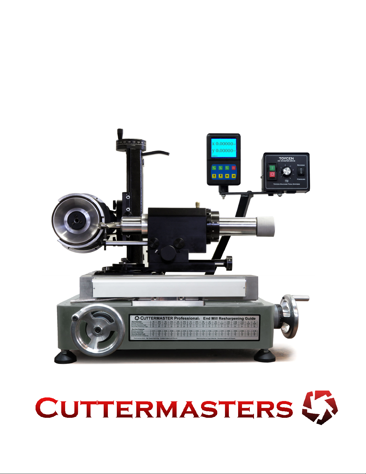
CUTTERMASTER Professional CM-01P User’s Manual
Page 6
are precision honed and capable of grinding to close tolerances. The spindle sleeve is made from
stainless steel and the spindle itself is chrome plated steel.
The Toycen Radius Air Bearing has a 180° swivel base for radius grinding and takes standard 5C
colletool spindle with end mill holders available that can hold shank sizes up to 2”. The Toycen In-
niteTwinMotorTowerprovideseasyandaccuratepositioningofthewheelstothetoolbeingground
and allows two wheels to be set and trued allowing for the indexing of one wheel to the next which is
intended to reduce set up times. The table is cast, aged monolithic grey iron.
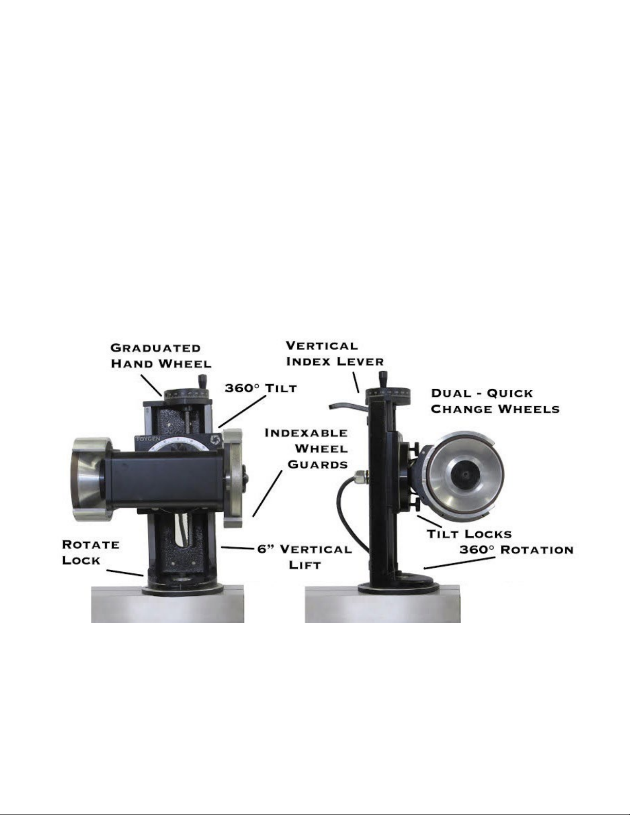
The DC Motor comes standard with two spindles so motor/spindle assembly tilt to positive and nega-
tive angles and rotates 360°. Cutting tool clearance angles can be adjusted as needed providing real
angle result when setting angles.
There are 9 different axes to work with for unlimited versatility. Your CM-01P grinds O.D.s (outside
diamters)andendsofstandardendmillsinonesetupwithinafewminutes.insideutes,ends
(primary and secondary), as well as roughing end mills, carbide tools, reamers, end gashes, small
roundsorreamers(circumferentiallands),reducedneckgrinds,Weldonats,carbideandHSScut
off.
Theory Behind the CM-01P DC Tower
TheoriginalCUTTERMASTERwasdesignedin1972whentheprevailingendmillswerelongerute,
HighSpeedSteel(HSS),30degreehelix,ballnose2,4,and6ute.Todayweseedifferentgeome-
tries,widespreaduseofcarbide,smallcornerradii,reducednecks,andcuttermodicationsaremore
prevalent. HSS tools can be ground until the geometry won’t run any longer and this is not the case
with carbide. Carbide fails over time or with heat, whereas steel gets dull. This being said, cutting off
and grinding ends and corner radiuses has become more important.
Most grinders have a single speed AC motor, designed to be inexpensive for the manufacturers to
produce. This is not conducive to a good tool grinding environment where conditions vary from tool to
tool. DC motors have more torque throughout their variable range of speeds allowing for deeper cuts
without heat damage to the tool, given that it is a dry grinding environment. The twin wheel head of
theCM-01PDCTowercanbeipped,reversedandspeedadjustedtosuitmostanygrindingrequire-
ment.
Onthetopicofwheels,ourwheelshavebeenspecicallydesignedfordrygrindingandgoodbal-
ance. Once you get your wheels dialed in, you can work from wheel to wheel without having to re-
mount and dial in as frequently.