kincrome K13235 User manual

AIR ANGLE
GRINDER 100MM
K13235
ED1 Sept 15
UNIQUE
TWIN BEARING
SYSTEM
LOW
AIR
CONSUMPTION
COMPOSITE
ERGONOMIC
GRIP
U N I Q U E
TWIN BEARING
SYSTEM
2
YEAR
WARRANTY

1
AIR ANGLE GRINDER 100MM
Table of Contents
Know Your Product ...................................................................................................1
General Safety Instructions .....................................................................................2
Additional Safety Instructions..................................................................................3-4
Assembly....................................................................................................................4-5
Operation...................................................................................................................5-6
Maintenance & Warranty .........................................................................................6
Parts Breakdown......................................................................................................7
Know your product
1. Safety Guard
2. Outer Flange
3. Inner Flange
4. Side Handle
5. Swivel Exhaust
6. Grinder Body
7. Air Inlet
8. Trigger
9. Trigger Lock Off
10. Spindle Spanner
11. Pin Wrench
12. Nitto Style Fitting
Model No:................................................................................................................... K13235
Description: .............................................................................................................. Angle Grinder 100mm
Free Speed:................................................................................................................ 10,000RPM
Spindle Size: ........................................................................................................... M10x1.5mm
Air Inlet: ..................................................................................................................... ¼”
Avg Air Consumption: .......................................................................................... 99LPM (3.5CFM)
Air Pressure Maximum:........................................................................................... 90PSI
Max Hose Length: ..................................................................................................... 10 Meter
Min. Hose Inner Diameter: ...................................................................................... 3/8” (10mm)
Overall Length .......................................................................................................... 244mm
Weight ....................................................................................................................... 1.4kg
1
2
3
4
56
7
8
9
10 11 12

2
AIR ANGLE GRINDER 100MM
General Safety Warnings
Save all warnings and instructions for future reference.
WARNING! Read all safety warnings and all instructions. Failure to follow the warnings and instructions may
result in fire and/or serious injury.
1) Work Area
a) Keep the work area clean and well lit. Cluttered benches and dark areas increase the risks of electric shock, fire, and
injury to persons.
b) Do not operate the tool in explosive atmospheres, such as in the presence of flammable liquids, gases, or dust. The tool is
able to create sparks resulting in the ignition of the dust or fumes.
c) Keep bystanders, children, and visitors away while operating the tool. Distractions can result in loss of control of the tool.
d) Keep children and bystanders away while operating any powered product Distractions can cause you to lose control.
2) Personal Safety
a. Stay alert. Watch what you are doing and use common sense when operating the tool. Do not use the tool while tired or
under the influence of drugs, alcohol, or medication. A moment of inattention while operating the tool increases the risk of
injury to persons.
b. Dress properly. Do not wear loose clothing or jewellery. Contain long hair. Keep hair, clothing, and gloves away from
moving parts. Loose clothes, jewellery, or long hair increases the risk of injury to persons as a result of being caught in
moving parts.
c. Avoid unintentional starting. Be sure the switch is off before connecting to the air supply. Do not carry the tool with your
finger on the switch or connect the tool to the air supply with the switch on.
d. Remove adjusting keys and wrenches before turning the tool on. A wrench or a key that is left attached to a rotating part of
the tool increases the risk of personal injury.
e. Do not overreach. Keep proper footing and balance at all times. Proper footing and balance enables better control of the
tool in unexpected situations.
f. Use safety equipment. A dust mask, non-skid safety shoes and a hard hat must be used for the applicable conditions. Wear
heavy-duty work gloves during use.
g. Always wear eye protection. Wear approved safety eye protection.
h. Always wear hearing protection when using the tool. Prolonged exposure to high intensity noise can contribute to
hearing loss.
3) Tool Use and Care
a. Use clamps or other practical ways to secure and support the workpiece to a stable platform. Holding the work by hand or
against the body is unstable and can lead to loss of control.
b. Do not force the tool. Use the correct tool for the application. The correct tool will do the job better and safer at the rate for
which the tool is designed.
c. Do not use the tool if the switch does not turn the tool on or off. Any tool that cannot be controlled with the switch is
dangerous and must be repaired, at an authorised repair agent.
d. Disconnect the tool from the air source before making any adjustments, changing accessories, or storing the tool. Such
preventive safety measures reduce the risk of starting the tool unintentionally. Turn off and detach the air supply, safely
discharge any residual air pressure, and release the throttle and/or turn the switch to its off position before leaving the
work area.
e. Store the tool when it is idle out of reach of children and other untrained persons. A tool is dangerous in the hands of
untrained users.
f. Maintain the tool with care. A properly maintained tool is easier to control.
g. Check for misalignment or binding of moving parts, breakage of parts, and any other condition that affects the tool’s
operation. If damaged, have the tool serviced before using. Many accidents are caused by poorly maintained tools.

3
AIR ANGLE GRINDER 100MM
4) Service
a. Tool service must be performed only by qualified repair personnel.
b. When servicing a tool, use only identical replacement parts. Use only authorized parts.
c. Use only the lubricants specified by the manufacturer.
5) Additional Safety Warnings
a. The warnings and precautions discussed in this manual cannot cover all possible conditions and situations that may
occur. It must be understood by the operator that common sense and caution are factors which cannot be built into this
product, but must be supplied by the operator.
b. Only use with accessories rated to handle the speeds exerted by this tool during operation. Other accessories not
designed for the speeds generated may break and forcefully launch pieces.
c. Attach all accessories properly to the tool before connecting the air supply. A loose accessory may detach or break
during operation.
d. Thoroughly read and understand the manual for the air compressor used to power this tool.
e. Install an in-line shutoff valve to allow immediate control over the air supply in an emergency, even if a hose is ruptured.
f. Use this tool with both hands only. Using tools with only one hand can result in loss of control.
g. Do not lay the tool down until it has come to a complete stop. Moving parts can grab the surface and pull the tool out of
your control.
h. Do not force the tool. Use a larger one if needed.
i. Use a clamp or vice to secure the workpiece in place. It is safer than using your hand and keeps both hands free to
operate the airtool
j. Do not hold flanges, accessories or adapters during use.
k. Anyone using vibrating tools regularly or for an extended period should first be examined by a doctor and then have
regular medical check-ups to ensure medical problems are not being caused or worsened from use. Pregnant women
or people who have impaired blood circulation to the hand, past hand injuries, nervous system disorders, diabetes, or
Raynaud’s Disease should not use this tool. If you feel any symptoms related to vibration (such as tingling, numbness, and
white or blue fingers), stop using the tool and seek medical advice as soon as possible.
l. Do not smoke during use. Nicotine reduces the blood supply to the hands and fingers, increasing the risk of
vibration-related injury.
m. Wear suitable gloves to reduce the vibration effects on the user.
6) Description of Symbols
The following symbols could be shown on the tool:
Read the instruction manual before use. Risk of Explosion
Wear Ear Protection Wear Eye Protection
no No-load speed, Free Speed CFM Cubic Feet per Minute flow
.../min, RPM Revolutions or reciprocation per minute SCFM Cubic Feet per Minute flow at
standard conditions
PSI Pounds per square inch of pressure NPT National pipe thread, tapered
ft-lb Foot-pounds of torque BPM Beats/ Blows per minute
Nm Newton meters of force BSP British standard pipe

4
AIR ANGLE GRINDER 100MM
7) ADDITIONAL SAFETY INSTRUCTIONS FOR ANGLE GRINDERS
a. Use only wheel (disc) types that are recommended for your air tool and the specific guard designed for the selected
wheel. Wheels for which the air tool was not designed cannot be adequately guarded and are unsafe.
b. The guard must be securely attached to the air tool and positioned for maximum safety, so the least amount of wheel
(disc) is exposed towards the operator. The guard helps to protect operator from broken wheel fragments and accidental
contact with wheel.
c. Wheels (discs) must be used only for recommended applications. For example: do not grind with the side of a cut-off
wheel. Abrasive cut-off wheels are not intended for grinding, side forces applied to these wheels may cause
them to shatter.
d. Always use undamaged wheel (disc) flanges that are of correct size and shape for your selected wheel. Proper wheel
flanges support the wheel thus reducing the possibility of wheel breakage. Flanges for cut-off wheels may be different from
grinding wheel flanges.
e. Do not use worn down wheels from larger power tools. Wheels intended for larger power tools are not suitable for the
higher speed of a smaller tool and may burst.
f. Make sure the wheel (disc) is not contacting the work piece before the tool is turned on. Having the wheel resting on the
work piece before starting the tool could result in the tool kicking as it grips the work piece, this could cause potential
personal harm and/or material damage.
g. Check the wheel (disc) carefully for cracks or damage before operation. Replace cracked or damaged wheels immediately.
h. Before operation of the tool an actual work piece, let it run for a few moments. Watch for vibration or wobbling that could
indicate poor installation of the wheel (disc) or a poorly balanced wheel.
i. Watch out for flying sparks. Hold the tool at an angle of approximately 15 - 30° to the work piece surface.
j. Use only wheels (discs) having a maximum operating speed at least as high as the “No load speed” stated in this manual.
Using a wheel with a lower maximum speed rating than the tool is dangerous and could result in the wheel breaking
during use causing potential personal harm and/or material damage.
k. It should never be necessary to force the tool. If rotational speed drops abnormally, the pressure should be released
immediately. Little more than the weight of the tool should be applied. Applying (forcing) excessive pressure can cause
dangerous wheel breakage or burn out of the tools motor.
l. Always wear eye protection, Wear goggles, Wear hearing protectionand a breathing mask.
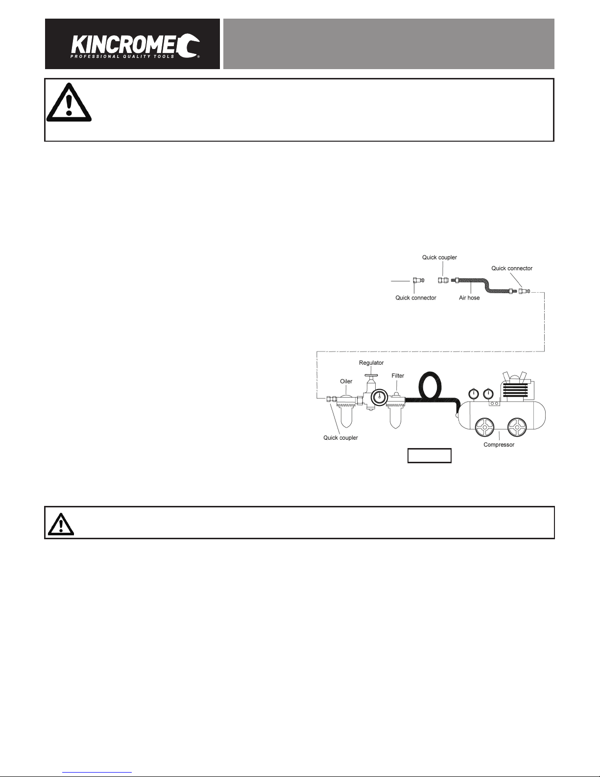
8) Assembly
Assembling the side handle
1. The side handle (4) must be fitted on the left side of the grinder body (6), opposite to the swivel exhaust (5).
2. Screw the side handle in place in a clockwise direction, with your hands. (Do not over tighten)
Removing the grinding disc
1. Always wait until the disc or attachment has stopped rotating before attempting to remove the disc.
2. Remove the outer flange (2) by hand if loose. If tight, use the spindle spanner (10) to secure the spindle (1) in place, then insert
the
pin wrench (11) into the outer flange, and turn anti-clockwise to remove.
Attaching the grinding disc
1. Holding the angle grinder with the spindle facing upwards, ensure the inner flange (3) is on the spindle and located correctly.
The two machined flat sections on one side of the inner flange (3) must face the angle grinder and locate in the appropriate
position on the spindle.
2. Insert the hole in the grinding/cutting disc over the angle grinder spindle, with the disc label facing the angle grinder.
3. The hole in the disc should be located onto the spindle. Ensure the hole in the disc locates and fits firmly into the ring section of
the inner flange (3).
4. Screw the outer flange (2) onto the spindle with the protruding ring section facing the angle grinder. This ring section must
locate with the hole in the grinding disc.
Note: When using ultra thin cut off discs’s, screw the outer flange (2) with the proturuding ring section facing outwards.
5. Tighten the outer flange (2) by locking the spindle by using the spindle spanner (10) and then tightening the outer flange (2) with
the pin wrench (11) provided.
6. Regularly check that the outer flange has not loosened during use.

5
AIR ANGLE GRINDER 100MM
WARNING! Do not fit or use a grinding disc for cutting applications - For cutting, use a cutting disc and ask your
hardware retailer for advice regarding the type of cutting disc you require for the material you wish to cut. Grinding
discs are used for grinding metal only.
WARNING! Using the grinder with the safety guard (1) removed is a serious safety concern, this action will also void
your warranty.
Safety guard
The safety guard (1) is assembled to your tool for your protection. The safety guard (1) will assist in protecting you from any dislodging
objects or materials that may be ejected by the cutting/grinding discs during normal operation. This safety guard (1) will assist in
protecting you from any accidental contact of the disc with your hands, fingers and any other parts of your body. To adjust the safety
guard (1), first disconnect the tool from the air supply. Now loosen the bolt securing the guard. Relocate the safety guard (1) into the
desired position, then refasten the bolts. Ensure the safety guard (1) is firmly secured prior to use.
9) Before Starting
TO PREVENT SERIOUS INJURY FROM EXPLOSION:
Verify compressor is off before setup. Use only clean, dry, regulated,
compressed air to power this tool. Do not use oxygen, carbon dioxide,
combustible gases, or any other bottled gas as a power source for
this tool.
1. It is recommended a filter, regulator with pressure gauge, oiler,
in-line shut-off valve, and quick coupler be fitted for optimal
operation, as shown on Figure A.
2. An in-line shut-off ball valve is an important safety device,
it will shut-off the air supply even if the air hose is ruptured.
The shut-off valve should be a ball valve because it can be
closed quickly.
Note: If an automatic oiler system is not used, add a 4 to 5 drops
of Kincrome Air Tool Oil to the air inlet before operation. Add a
1-2 drops every hour of continual use.
3. Attach an air hose to the compressor’s air outlet. Connect the air hose to the air inlet (7) of the tool. Other components, such as
a quick connect fitting and quick connect coupler, will make operation more efficient, but are not required.
WARNING! Do not install a quick coupler directly on the tool. Couplers contains an air valve that will allow the air tool to
retain pressure and inadvertently operate after the air supply is disconnected.
4. The air hose must be long enough to reach the work area and allow free movement while working.
5. Turn on the air compressor according to the manufacturer’s directions and allow the tank to build up pressure until it cuts-off.
6. Adjust the air compressor’s regulator so that the air output is at the tools recommended working pressure, the output must not
exceed the tool’s maximum air pressure at any time. Adjust the pressure gradually, while checking the air output gauge to set
the optimal pressure range.
7. Inspect all air connections for leaks. Repair any leaks.
8. If the tool is not be used, turn off and detach the air supply, safely discharge any residual air pressure, and release the trigger (8)
and/or turn the tools switch to its off position to prevent inadvertent operation.
Figure A

6
AIR ANGLE GRINDER 100MM
10) Operation
1. Screw in Nitto Style Fitting (7) to the air inlet (1). Thread (teflon) tape may be required to ensure a leak free seal.
2. Connect the air hose to the air inlet (1) of the tool.
3. To start the angle grinder push the trigger lock off (9) forward towards the grinder body (6), then gently squeeze the trigger (8) to
until the required speed is obtained.
4. To begin cutting or grinding, approach the material at an angle between 15 and 30 degrees to the wheel (disc). Maintaining the
angle until you have finished grinding/cutting. Do not force the wheel or apply too much pressure.
5. To turn the angle grinder OFF, release the trigger (8).
Caution: Do not exceed tool’s maximum air pressure rating (90 PSI). If tool still does not have sufficient force at maximum
pressure and sufficient airflow, then a larger tool may be required.
11) Cleaning, Maintenance, and Lubrication
Note: These procedures are in addition to the regular checks and maintenance explained as part of the regular operation of the air-
operated tool.
The air motor and bearing uses compressed air to power the tool. Moisture in compressed air will rust the motor components, you
must lubricate the motor daily, with Kincrome air tool oil.
Lubrication
1. Disconnect the tool from the air supply holding it so the air inlet (7) faces up.
2. Hold the trigger (8) down and put 4 to 5 drops of Kincrome Air Tool Oil in the air inlet. Holding the trigger down helps circulate
oil in the motor.
3. Connect the tool to air supply, cover the swivel exhaust (5) with a towel and run for a few seconds.
WARNING! Any excess oil in the motor is immediately expelled from the swivel exhaust (5) .Always direct swivel
exhaust (5) away from people or objects.
Storage
1. Avoid storing the tool in a location subject to high humidity. If the tool is left as it is used, the residual moisture inside the tool
can cause rust. Before storing and after operation, oil the tool and run it for a short time.
2. Regular inspection should be carried out of spindles, threads, and clamping devices in-respect of wear and for location of
abrasive products.
12) Warranty
Warranty given by Kincrome Australia Pty Ltd of 3 Lakeview Drive, Caribbean Park, Scoresby, Victoria (Tel 1300 657 528).
The applicable warranty period (24 months) commences on the date that the product is purchased. If this product has materials or
workmanship defects (other than defects caused by abnormal or non warranted use) you can, at your cost, send the product to place
of purchase, an authorised Kincrome service agent or one of Kincromes addresses for repair or replacement. Your rights under this
warranty are in addition to any other rights you have under the Australian Consumer Law or other applicable laws. Our goods come
with guarantees that cannot be excluded under the Australian Consumer Law. You are entitled to a replacement or refund for a major
failure and compensation for any other reasonably foreseeable loss or damage. You are also entitled
to have the goods repaired or replaced if the goods fail to be of acceptable quality and the failure does not amount to a major failure.
For further details please visit www.kincrome.com.au or call us. Due to minor changes in design or manufacture, the product you
purchase may sometimes differ from the one shown on the packaging..
IMPORTANT! If the tool fails to operate correctly, call customer service on 1800 657 528 for advice on the best resolution for your
situation. If a resolution cannot be achieved over the phone please take the tool and all related accessories to an authorised service
centre or place of purchase showing proof of purchase for assistance.

7
AIR ANGLE GRINDER 100MM
*Indicates stocked spare parts
13) Parts Breakdown

8
AIR ANGLE GRINDER 100MM
Notes:

www.kincrome.com.au
Table of contents
Other kincrome Grinder manuals