CyberOptics Imagenation PXD1000 Quick guide

1
Configuring the PXD1000 Digital Frame Grabber with a
Digital Camera and Building a Compatible Cable
Rev 1.1 12/00
The PXD1000 digital frame grabber is compatible with nearly all commercially available
40Mhz and below digital cameras. In order to use a digital camera with your PXD1000
digital frame grabber, a compatible cable and configuration file will be required.
Imagenation provides direct support with compatible cables and configuration files for a
number of the more popular digital cameras (see list below). Since support for new
models of digital cameras are being added on a regular basis, please check the
Imagenation Technical Support web page for an up-to-date list of all digital cameras with
full support located on the Web at: www.imagenation.com -> Technical Support -> PXD
Series.
If your camera is not listed as one currently being supported, you will need to take a few
more steps to configure the PXD1000 to work with your camera. With the powerful PXD
Configuration Utility, you can create a camera definition file for your particular camera
and nearly any 40Mhz or lower digital camera can be configured and optimized to
operate with the PXD1000.
Why Is It Necessary To Build a Unique Cable & Configuration File
For Each Digital Camera?
Due to a lack of industry standards in the digital camera world, it is typically necessary to
have a specially configured cable for the frame grabber and each digital camera make and
model. This is because in general each digital camera can have unique connectors, signal
pin-outs, data formats, and data widths (8, 10, 12 bits, etc…).
For example, suppose you plan to use a single channel 10-bit camera; the image data is
transmitted on 10 twisted pairs (20 wires). If the camera is generating the timing for the
frame grabber then at least Line-Data-Valid (LDV), Frame-data-valid (FDV), and the
camera pixel clock (CAMERACLK) will be required In addition, for example, if the
camera uses a single exposure control implemented with EIA-644 and you want the
frame grabber to control it, then another twisted pair is required. All in all, even this
simple application requires at least 14 twisted pairs.
Options for acquiring compatible digital cable:-
1) Purchase from Imagenation
Imagenation provides full support for a number of different digital
cameras. We provide camera guides, which include specific instructions
for configuring the PXD1000 for the camera. Some camera guides and
camera configuration files are located on the CD that comes with the

2
PXD1000. The Technical Support section of the Imagenaiton Web site
will contain the latest and most up-to-date information on supported
digital cameras.
The following is a partial list of supported cameras (see Web for updated
list www.imagenation.com as this list is constantly expanding).
Camera Configuration Files & Guides
BASLER
BA101 Basler Area Scan A101 (Previously A113)
BL102 Basler Line Scan L102 (Previously L130)
BL203 Basler Line Scan L203 (Previously L240)
DALSA
DALSA Dalsa CA-D4/D7
HITACHI
KPF100 Hitachi KPF 100
KODAK Kodak MASD has been acquired by Roper Scientific
ES10 Kodak Megaplus ES 1.0
ES14 Kodak Megaplus ES 1.4i
PULNIX
TM1001 Pulnix TM 1001-02
TM1010 Pulnix TM 1010
TM1040 Pulnix TM 1040
TM1300 Pulnix TM 1300
TM9701 Pulnix TM 9701
RETICON
RLS Reticon Line Scan
UNIQ
UNIQ UNIQ Cameras: UP-600, UP-1000, UP-1030, UP-900
2) Build your own cable:
If your camera is not listed you will need to create a camera definition file
and build a compatible cable. We provide an easy-to-use camera
configuration application and customizable cable assemblies that simplify
camera and frame grabber setup. If you decide to build the entire cable
you will need to consult your camera manual for the part number of the
connector used on the camera. The mating cable plug for the PXD1000 is
an AMP Amplimite .050 Series Cable Plug Connector, Series III (AMP
PN: 749621-9) or equivalent. Imagenation also has two kit options for
building your own cable from scratch:
1) Cable Kit CB-011 contains 50 twisted pairs and supports up to a full
32-bit camera.
2) Cable kit CB-012 contains 37 twisted pairs and is an option for one
and two channel digital camera implementations of 10-bits or less.

3
There is no standard for wiring any particular camera. Imagenation
provides information to help get you started on page 51 to page 53 in the
users guide.
Start by making a map of the connections as shown on page 53. You will
need to list all the required signals needed to drive your camera. In
addition to the data lines, most digital cameras require at least a Line-
Data-Valid (LDV), Frame-Data-Valid (FDV) and Pixel clock
(CAMCLK). Addition signals may be needed depending on the camera
used. These signals are most likely differential signals and require a
twisted pair for each signal.
The connection of the Data signals is a little more involved. To start with
Imagenation biases the Data connection to the upper bits of each channel.
This means that that your data bits from the camera need to be shifted.
Camera Data
Channel 1 PXD DATA
BITS Camera
Data
Channel 2
PXD DATA
BITS
8 Bit (0-7) -> Data Bits
(8-15) 8 Bit (0-7) -> Data Bits
(24-31)
10 Bit (0-9) -> Data Bits
(6-15) 10 Bit (0-9) -> Data Bits
(22-31)
12 Bit (0-12) -> Data Bits
(4-15) 12 Bit (0-12) -> Data Bits
(20-31)
16 Bit (0-15) -> Data Bits
(0-15) 16 Bit (0-15) -> Data Bits
(16-31)
24 Bit (8-31) -> Data Bits
(8-31)
32 Bit (0-31) -> Data Bits
(0-31)
Also note that these signals always require two wires per signal. The J2
connector shown in Figure 1 of this guide (page 52 in the PXD1000 Users
Manual) shows these signal labeled as Data(-) on the left and Data(+) on
the right.
Data(-) - Data Bits 0-31 to pins 98-67
Data(+) - Data Bits 0-31 to pins 48-17
Here is some basic information on the J2 data connector for pins 1-15 and
65-51 on the PXD1000 Digital Frame grabber.

4
CAMCLK(-) - pin 65 & CAMCLK(+) - pin 15
Name: Camera Clock
Signal provided by: Camera
Purpose: indicates when Pixel is valid
Signal: Rising sensitive
LDV(-) - pin 64 & LDV(+) - pin 14
Name: Line Data Valid
Signal provided by: Camera
Purpose: tells which pixel is valid for a line
Signal: High or Low depending on camera
FDV(-) - pin 63 & FDV(+) - pin 13
Name: Frame Data Valid
Signal provided by: Camera
Purpose: Tells which lines are valid for frame
Signal: High or Low depending on camera
HD(-) - pin 61 & HD (+) - pin 11
Name: Horizontal Drive
Signal provided by: Frame Grabber
Purpose: Tells camera to provide a valid Pixel in line
Signal: High or low depending on camera
VD(-) - pin 60 & (+) - pin 10
Name: Vertical Drive
Signal provided by: Frame Grabber
Purpose: Tells camera to provide a valid line
Signal: High or low depending on camera
Ground/Strobe#0(-) - pin 59 & Strobe#0(+) - pin 59
Name: Strobe 0
Signal provided by: Frame Grabber
Purpose: Provides a series of timed pulses for use by application
Signal: Pulse train of gap, pulse, gap, pulse …
Ground/Strobe#1(-) - pin 58 & Strobe#1(+) - pin 8
Name: Strobe 1
Signal provided by: Frame Grabber
Purpose: Provides a series of timed pulses for use by application
Signal: Pulse train of gap, pulse, gap, pulse …
Synthclk(-) - pin 57 & Synthclk(+) - pin 7
Name: Synth Clock
Signal provided by: Frame Grabber
Purpose: Instructs camera to provide another pixel

5
Signal: Rising edge sensitive
WEN(-) - pin 56 & WEN(+) - pin 6
Name: Write Enable
Signal provided by: Camera
Purpose: Defined by camera
FIELD(-) - pin 55 & FIELD(+) - pin 5
Name: Field
Signal provided by: Camera
Purpose: signal for even or odd field for interlaced output
CTRL#0(-) - pin 54 & CTRL#0(+) - pin 4
Name: Control 0
Signal provided by: Frame Grabber
Purpose: Provides TTL output for use by application
CTRL#1(-) - pin 53 & CTRL#1(+) - pin 3
Name: Control 1
Signal provided by: Frame Grabber
Purpose: Provides TTL output for use by application
CTRL#2(-) - pin 52 & CTRL#2(+) - pin 2
Name: Control 2
Signal provided by: Frame Grabber
Purpose: Provides TTL output for use by application

6
Figure 1 Data connector (J2)

7
The I/O Connector (Optional)
All other signals (except for camera data and timing) are available at the I/O
connector. This includes the trigger, strobes and two general-purpose inputs and
two outputs. Figure 4.2 shows the signals on the I/O connector
3) Build from cable with compatible FG connector
For cameras where standard cables are not available, you can purchase an
Imagenation cable-kit and build one or make your own from scratch. In
addition you will need to consult your camera manual for the part number
of the connector used on the camera and get the pin out of the camera
connector from the camera manufacturer.
If you use a camera that has 10 or fewer data bits, we recommend that you
use Cable Kit CB-012-00. With some cameras every data line may need to
be terminated to 200mv (provided at pin 66 of J2), In this case the smaller
cable will have fewer wires that need to be terminated.
Making a data cable for 10-bit and Smaller Cameras
Cable kit CB-012-00 is appropriate for cameras with up to 10 data
bits. This includes all single channel cameras and two channel cameras
with up to 10 bits per channel. (Note: the PXD1000 manual incorrectly

8
states that the CB-012-00 kit was appropriate for single channel digital
cameras of up to 20-bits)
The kit contains a cable with 37 twisted pairs of wires terminated on one
end by a 100-pin connector, which mates to the PXD1000. On the other
end the wires have been prepared for attaching to a connector (which you
must supply) that mates to your camera.
Cable kit CB-012-00
Signal Pin Wire Color Pin Signal
(Wire/Stripe)
GROUND 1 Purple/Orange 51 Orange/Purple GROUND
2NC 52NC
CRTL1(+) 3 Blue/Orange 53 Orange/Blue CRTL1(-)
CRTL0
(
+
)
4Gra
y
/Oran
g
e54Oran
g
e/Gra
y
CRTL0
(
-
)
FIELD(+) 5 Brown/Pink 55 Pink/Brown FIELD(-)
WEN(+) 6 Green/Yellow 56 Yellow/Green WEN(-)
SYNTHCLK(+) 7 Green/Orange 57 Orange/Green SYNTHCLK(-)
STROBE1(+) 8 Brown/Orange 58 Orange/Brown GND/STROBE1(-)
STROBE0(+) 9 Pink/White 59 White/Pink GND/STROBE0(-)
VD
(
+
)
10 Blue/Yellow 60 Yellow/Blue GND/VD
(
-
)
HD(+) 11 Brown/Yellow 61 Yellow/Brown GND/HD(-)
GROUND 12 Brown/White 62 White/Brown GROUND
FDV(+) 13 Orange/Yellow 63 Yellow/Orange FDV(-)
LDV(+) 14 Gray/Tan 64 Tan/Gray LDV(-)
CAMCLK(+) 15 Purple/Tan 65 Tan/Purple CAMCLK(-)
GROUND 16 Gra
y
/Pink 66 Pink/Gra
y
200MV
Data31(+) 17 White/Orange 67 Orange/White Data31(-)
Data30(+) 18 Brown/Green 68 Greeen/Brown Data30(-)
Data29(+) 19 Purple/Yellow 69 Yellow/Purple Data29(-)
Data28(+) 20 White/Yellow 70 Yellow/White Data28(-)
Data27(+) 21 Brown/Blue 71 Blue/Brown Data27(-)
Data26
(
+
)
22 Tan/White 72 White/Tan Data26
(
-
)
Data25(+) 23 Purple/Pink 73 Pink/Purple Data25(-)
Data24(+) 24 Blue/Tan 74 Tan/Blue Data24(-)
Data23(+) 25 Blue/Pink 75 Pink/Blue Data23(-)
Data22(+) 26 Purple/White 76 White/Purple Data22(-)
27 NC 77 NC
28 NC 78 NC
29 NC 79 NC
30 NC 80 NC
31 NC 81 NC
32 NC 82 NC
Data15(+) 33 Blue/White 83 White/Blue Data15(-)
Data14
(
+
)
34 Brown/Tan 84 Tan/Brown Data14
(
-
)
Data12(+) 35 Tan/Pink 85 Pink/Tan Data13(-)
Data13(+) 36 Gray/Yellow 86 Yellow/Gray Data12(-)
Data11(+) 37 Brown/Purple 87 Purple/Brown Data11(-)
Data10(+) 38 Brown/Gray 88 Gray/Brown Data10(-)
Data9(+) 39 Tan/Green 89 Green/Tan Data9(-)
Data8
(
+
)
40 Green/Pink 90 Pink/Green Data8
(
-
)
Data7(+) 41 Pink/Yellow 91 Yellow/Pink Data7(-)

9
Data6(+) 42 Tan/Yellow 92 Yellow/Tan Data6(-)
43 NC 93 NC
44 NC 94 NC
45 NC 95 NC
46 NC 96 NC
47 NC 97 NC
48 NC 98 NC
GROUND 49 Tan/Orange 99 Orange/Tan +12V_FUSED
GROUND 50 Orange/Pink 100 Pink/Orange +12V_FUSED
Making a data cable for 11-bit to 32-bit Cameras
Cable kit CB-011-00 is appropriate for cameras from 11 data bits to 32
data bits.
The kit contains a cable with 50 twisted pairs of wires terminated on one
end by a 100-pin connector, which mates to the PXD1000. On the other
end the wires have been prepared for attaching to a connector (which you
must supply) that mates to your camera.
Cable kit CB-011-00
Si
g
nal Pin Wire Colo
r
Pin Wire Colo
r
Si
g
nal
(Wire/Stripe) (Wire/Stripe)
GROUND 1 Purple/Orange 51 Orange/Purple GROUND
CRTL2(+) 2 Green/White 52 White/Green CRTL2(-)
CRTL1(+) 3 Blue/Orange 53 Orange/Blue CRTL1(-)
CRTL0(+) 4 Gray/Orange 54 Orange/Gray CRTL0(-)
FIELD(+) 5 Brown/Pink 55 Pink/Brown FIELD(-)
WEN(+) 6 Green/Yellow 56 Yellow/Green WEN(-)
SYNTHCLK(+) 7 Green/Orange 57 Orange/Green SYNTHCLK(-)
STROBE1(+) 8 Brown/Orange 58 Orange/Brown GND/STROBE1(-)
STROBE0(+) 9 Pink/White 59 White/Pink GND/STROBE0(-)
VD(+) 10 Blue/Yellow 60 Yellow/Blue GND/VD(-)
HD(+) 11 Brown/Yellow 61 Yellow/Brown GND/HD(-)
GROUND 12 Brown/White 62 White/Brown GROUND
FDV(+) 13 Orange/Yellow 63 Yellow/Orange FDV(-)
LDV(+) 14 Gray/Tan 64 Tan/Gray LDV(-)
CAMCLK(+) 15 Purple/Tan 65 Tan/Purple CAMCLK(-)
GROUND 16 Gray/Pink 66 Pink/Gray 200MV
Data31(+) 17 White/Orange 67 Orange/White Data31(-)
Data30(+) 18 Brown/Green 68 Greeen/Brown Data30(-)
Data29(+) 19 Purple/Yellow 69 Yellow/Purple Data29(-)
Data28(+) 20 White/Yellow 70 Yellow/White Data28(-)
Data27(+) 21 Brown/Blue 71 Blue/Brown Data27(-)
Data26(+) 22 Tan/White 72 White/Tan Data26(-)
Data25(+) 23 Purple/Pink 73 Pink/Purple Data25(-)
Data24(+) 24 Blue/Tan 74 Tan/Blue Data24(-)
Data23(+) 25 Blue/Pink 75 Pink/Blue Data23(-)
Data22(+) 26 Purple/White 76 White/Purple Data22(-)
Data21(+) 27 Blue/Gray 77 Gray/Blue Data21(-)
Data20(+) 28 Blue/Purple 78 Purple/Blue Data20(-)

10
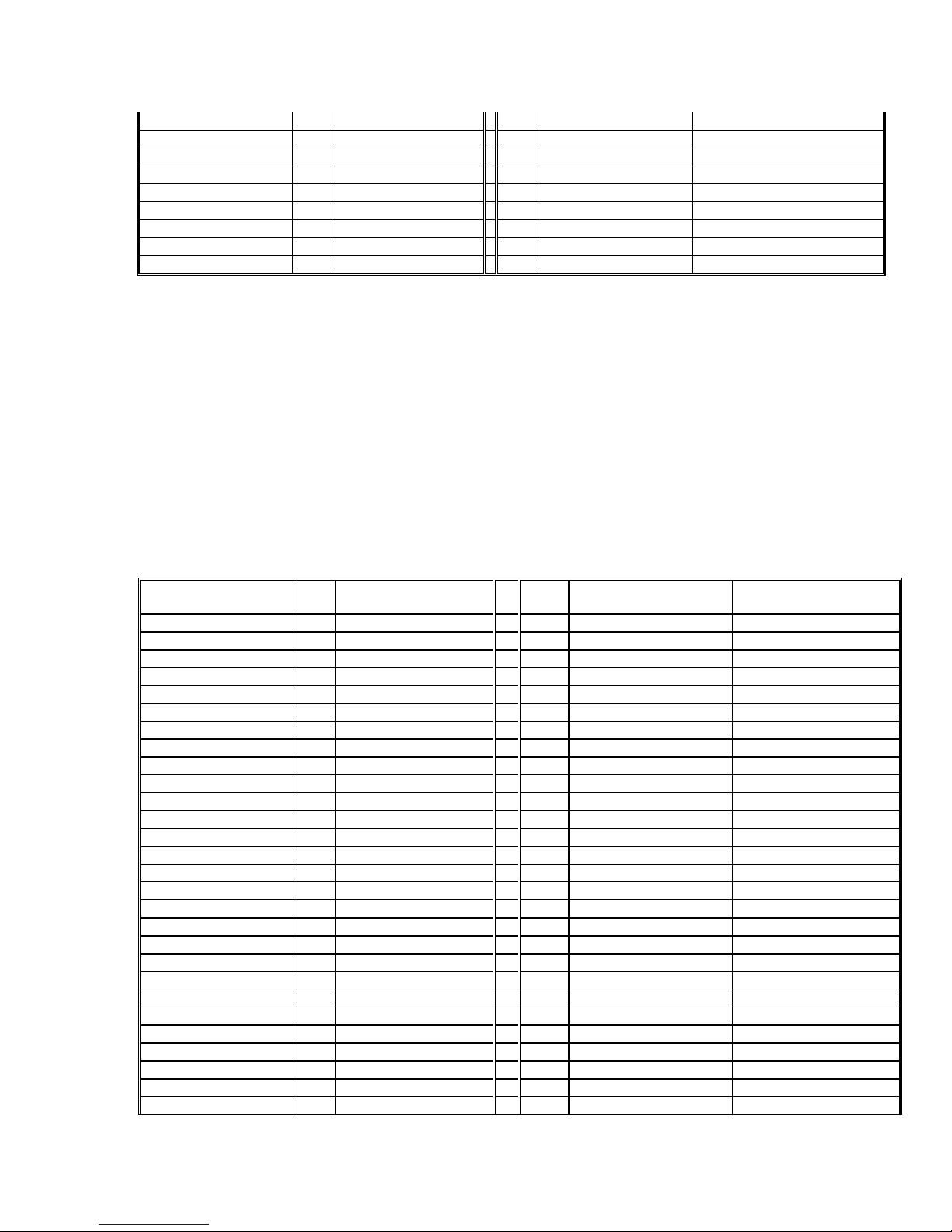
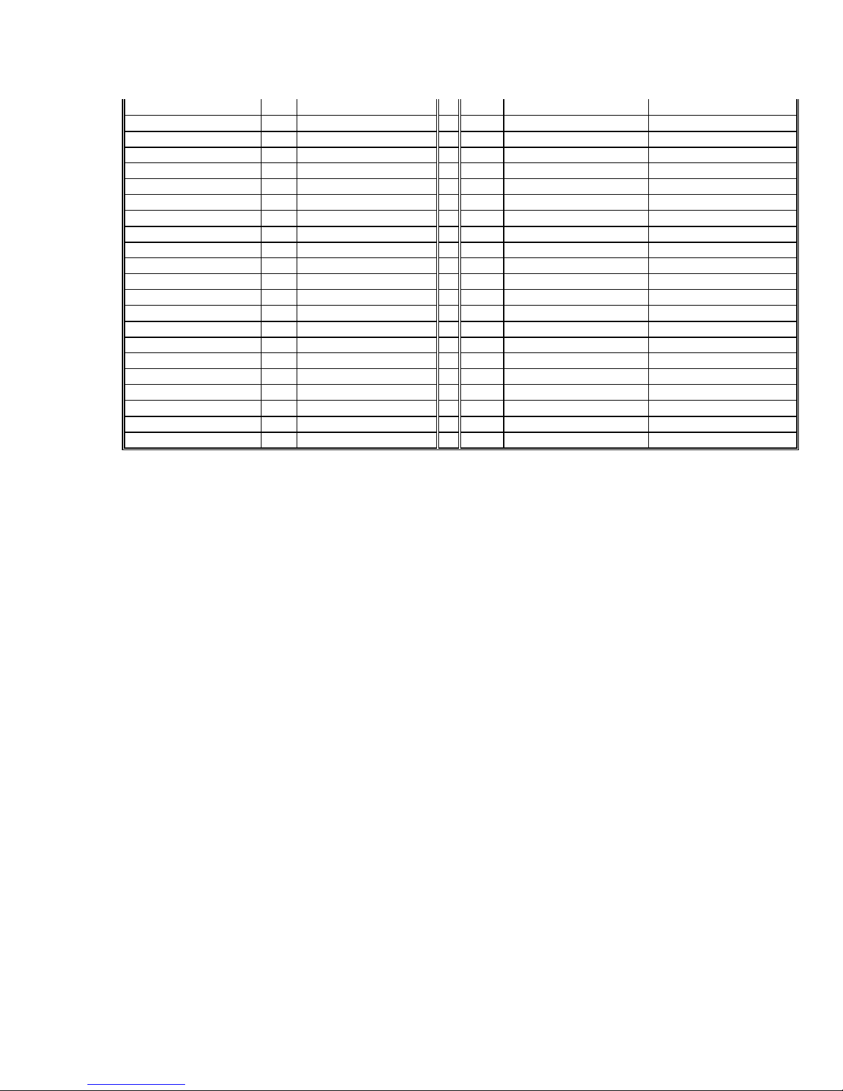
Data19(+) 29 Blue/Green 79 Green/Blue Data19(-)
Data18(+) 30 Green/Purple 80 Purple/Green Data18(-)
Data17(+) 31 Gray/Purple 81 Purple/Gray Data17(-)
Data16(+) 32 Gray/Green 82 Green/Gray Data16(-)
Data15(+) 33 Blue/White 83 White/Blue Data15(-)
Data14(+) 34 Brown/Tan 84 Tan/Brown Data14(-)
Data12(+) 35 Tan/Pink 85 Pink/Tan Data13(-)
Data13(+) 36 Gray/Yellow 86 Yellow/Gray Data12(-)
Data11(+) 37 Brown/Purple 87 Purple/Brown Data11(-)
Data10(+) 38 Brown/Gray 88 Gray/Brown Data10(-)
Data9(+) 39 Tan/Green 89 Green/Tan Data9(-)
Data8(+) 40 Green/Pink 90 Pink/Green Data8(-)
Data7(+) 41 Pink/Yellow 91 Yellow/Pink Data7(-)
Data6(+) 42 Tan/Yellow 92 Yellow/Tan Data6(-)
Data5(+) 43 Gray/White 93 White/Gray Data5(-)
Data4(+) 44 Green 94 Yellow Data4(-)
Data3(+) 45 Tan 95 White Data3(-)
Data2(+) 46 Purple 96 Orange Data2(-)
Data1(+) 47 Brown 97 Gray Data1(-)
Data0(+) 48 Blue 98 Pink Data0(-)
GROUND 49 Tan/Orange 99 Orange/Tan +12V_FUSED
GROUND 50 Orange/Pink 100 Pink/Orange +12V_FUSED
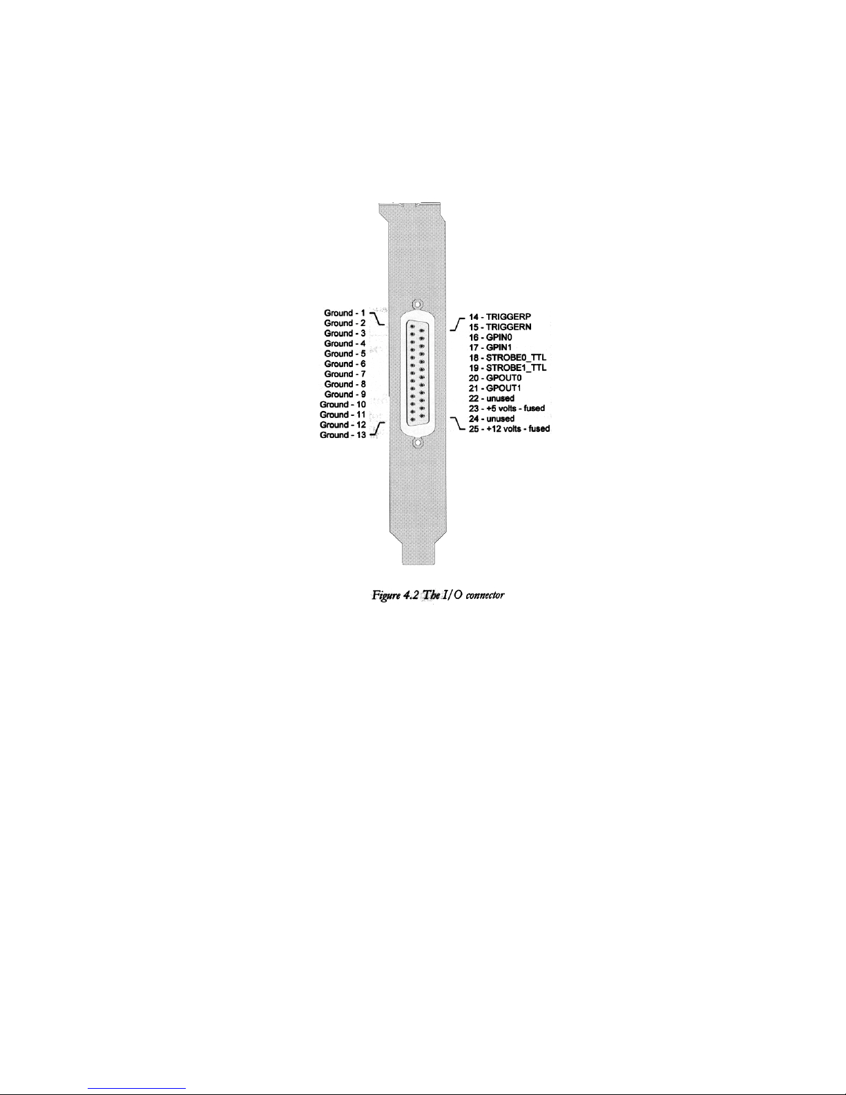
a. Build from cable with compatible Camera connector
If you plan to build a cable using a compatible Camera connector then you
will need a compatible mating cable plug for the PXD1000. The mating
cable plug for the PXD100 is an AMP Amplimite .050 Series Cable Plug
Connector, Series III (AMP PN: 749621-9) or equivalent
b. How long can the Digital Cable be? Imagenation recommends that the
cables for the digital camera to PXD1000 be 10 meters in length or less. If
cables are any longer than 10 meters, unpredictable results may occur.
There is not an easy answer to this question for cables longer than 10
meters. Cables up to 10 meters should work for all cameras. Beyond 10
meters, the answer begins to depend more on the camera and the speed of
the data than on the frame grabber. In general, the higher the speed, the
shorter the cable. A 40MHz camera, for example, would need a shorter
cable than a 20 MHz camera.
The problem with a long cable is that the wire sets up a distributed
capacitance. It can change the timing of the bits. If the timing of the bits
changes then the frame grabber will miss data. A high quality camera will
have a guard band on the bits to compensate for some small timing
changes.
LVDS is designed to allow cables up to several hundred feet, however,
much of that depends on the camera and the frequency.

11
Regardless of if your cable ends up being longer or shorter than 3 meters,
all cable wires must be of equal length due to the extremely sensitive
timing characters of the Frame Grabber and Digital Camera interface.
The PXD Configuration Application
Imagenation provides a program called PXD Configuration Application which
is used to create a configuration file for your digital camera. The following
described each box in configuration application
Setting the camera Information (Select Camera Information Tab)
a) Pixel Type (also known as bit depth)
i. Y8, Y10, Y12, RGB32
b) Camera Type
i. Area Scan
ii. Line Scan or TDI
Image Geometry (Select Image Geometry Tab)
a) Image Size (Set resolution for camera used)
i. Width (in pixels)
ii. Height (in pixels)
b) Image format (set appropriately for camera used)
i. First button is for single channel, non-interlaced camera
ii. Second button for single channel, interlaced camera
iii. Next Three buttons are for 2-Channel cameras.
iv. Next Three buttons are for 4-Channel cameras.
v. The Custom button allows you to define a new format.
Exposure Timing (Select Exposure Timing Tab)
a) Exposure control Type
i. Async for cameras that generate frames that are occasionally
controlled by something other than the frame grabber. For example
this setting can be used to generate a frame only when it is
triggered by some external mechanism (snap-shot mode).
ii. Free run for cameras that output continuous frames of video based
on internal timing or synched to the drive signals from the grabber.
(Live video mode)
iii. Strobes to set the frame grabber to generate strobe signals at the
strobe0 and strobe1 pins. This can be used to program the exposure
or integration time or used as a general-purpose output signal or
strobe light.
b) Strobe 0 and Strobe 1.
i. This sets the polarity of the output to high true or low true.
c) Camera Control 0,1,2
i. This sets the polarity of the general-purpose control pins High true
or Low true.

12
d) Exposure and Strobe Timing Settings (Exposure control Type set to
strobe)
i. Exposure type
a. Strobes set the frame grabber to generate signals at the
strobe0 and strobe1 pins. These signals can be used to
program the exposure or integration time of the camera.
b. Fixed Exposure means that the camera’s exposure is not
adjustable. You can still program the strobes, but the
exposure time features are not available.
c. Unknown Exposure is used if the exposure is unknown or
not programmable. In this case, the strobes do not control
the exposure and are used for other output.
d. Variable Exposure allows you to set exposure timing within
a software application. The exposure time is added to the
strobe duration if only 1 strobe is enabled or to the time
between strobes if 2 strobes are enabled
e) Delay and Period
i. Delay and Period are part of the strobe timing. They set the delay
between strobes and the period of each strobe pulse. Strobes set the
frame grabber to generate signals at the Strobe#0 and Strobe#1
pins.
Setting the Video Timing (Select the Video Timing tab)
a) Enter Pixel clock speed (from the camera specification)
i. The pixel clock speed is used to set the clock generator of the frame
grabber. This setting must be correct in order for the camera to work
properly.
b) Set the Frame Speed.
i. If the exposure time on your camera (which should be listed in
your camera manual) is longer than the minimum frame period,
use Variable
c) Set the Horizontal and Vertical Sync.
i. Number clocks before valid pixels from the horizontal sync
ii. Number of lines before valid image lines from the vertical sync
iii. You most likely will find the horizontal and vertical sync
information in your camera's manual or you can derive it from the
timing diagram in the camera manual. You can also experiment
with the numbers and see what works best.
Advanced Video Timing (Select the tab and enter the appropriate information)
a) For cameras that use Horizontal Drive, the frame grabber generates an
Hdrive pulse and the camera synchronizes to it. The camera then generates
an LDV (Line Data Valid) signal and sends it back to the frame grabber.
The frame grabber uses the LDV to detect the starting pixel of each line
from the camera.

13
i. Pulse Width: in number of clocks
ii. Output polarity: Low or High true
iii. Strobe#l wire: Output the HDrive signal to strobe1 and strobe1 ++1
wires in addition to the HDrive wire
iv. Clocks from Data to Hsync: number of clocks from last pixel on the
line to following horizontal sync.
v. For cameras that use Vertical Drive, the frame grabber generates a V
drive pulse and the camera synchronizes to it. The camera then
generates an FDV (Frame Data Valid) signal and sends it back to the
frame grabber. The frame grabber uses the FDV to detect the starting
line of each frame from the camera.
•Pulse Width: in number of clocks
•Output polarity: Low or High true
•Strobe#O wire: Output the VDrive signal to strobe#O and
strobe#O++l wires in addition to the VDrive wire
•Clocks from Data to V sync: number of lines from last line to fol-
lowing vertical sync.
b) If your camera is an interlaced camera, enter the appropriate information
under Interlace Control.
•Starting Field: either O or 1
•First Line Length: Length of the first line on field 0 and field 1. Both
fields are usually set to the width of the image size.
•Vdrive offset: Number of pixel clocks after the edge of the Hdrive that
•Vdrive goes active.
c) If your camera requires a clock from the PXDl000 set the Clocks per Pixel.
Most cameras require one clock per pixel, but some require two. Refer to your
camera manual for the correct setting.
d) Set the Strobe/Drive Signal. This is the type of output signals generated by the frame
grabber (either RS422 or TTL), for HDrive, VDrive, strobeO, and strobel.
Relationship to various pins
Camera Control 0,1,2 general purpose control pins can be used to control
camera modes. For example the Dalsa CA-D7 camera has features, which
cause the camera to output only half the resolution but at faster frame rate.
The control pin can be used to control this feature on this camera. (Refer to
page 43 of the user guide).
Troubleshooting tips and hints when using the PXD Configuration
Application.
Shape edges or ring around the images:
Shape edges or rings around the image on the screen may indicate that the
pixel clock lines need to be swapped. Swap the lines in the cable to the pixel
clock CAMCLK(-) - pin 65 & CAMCLK(+) - pin 15 and see if the problem
goes away.

14
Dim image:
•With smooth gradations -Try Increase lighting, check cameras F-
Stop, Exposure control settings.
•With banding-Check cable wiring of the data bits. Remember that
Imagenation biases the Data connection to the upper bits of each
channel. If this is wrong you may not be seeing all the bits.
All Black image:
§Check cable wiring.
FDV, LDV, Pixel Clock hook up.
§Check Power connector to camera. (if power from FG check to see
if power connector is hooked up to PXD1000.
§Is the camera shutter open.
§Try setting Configuration Application to free running mode.
§Some cameras have enable line that needed to be connected to
Control0, which will need to be set High in the Configuration
Application.
§Check Exposure setting.
§Is the image depth set correct in the Configuration Application
Y8, Y10, Y12 or RGB32.
Output formats/standards – i.e. RS422, TTL, LDVS(?)
RS644/RS422 are the type of input/output signal generated by the camera.
They are parallel differential signal (The state of the signal at the receiver
is determine by the potential difference between two wires)
The Interface data receivers are LVDS on the data connector and the
signals on the I/O connector are single ended TTL only (Reference pages
51-58 and 336 of our manual). The LDVS lines will work with standard
TTL levels but require a change to the cable wiring to the connector. The
type of output signal generated by the frame grabber (single ended TTL or
differential RS422) can be set for Hdrive, Vdrive, strobe0 and strobe1.
Note that the strobe outputs on the I/O connector are TTL level signals
only.
TTL : Transistor Transistor Logic (5v Level true)
LVTTL: Low Voltage Transistor Transistor Logic ( 3.3 Volt Level True )
LVDS: Low Voltage Differential Signals (The state of the signal at the
receiver is determined by the potential difference between two wires.)

15
Digital Frame Grabber Information
The WEN Signal
This single is an input to the frame grabber from the camera and is
typically treated as a FTV (Field Data Valid). This signal is available on
I/O line 1. The signal can be set to trigger a grab using the
SetTriggerSource function.
Data line Options
8 bit, 10 bit, 12 bit, 14 bit, 16 bit , 32 bit – Bits/Pixel
For a monochrome camera this describes the maximum number of
resolvable gray levels that the camera can provide. Eight bits per pixel
(256 gray levels) is quite common with 10, 12 and 14 bits/pixel available
in some models. A distinct advantage of digital camera results from
having the digital-to-analog converter moved from the frame grabber card
into the camera. This reduces the effects of transmission line noise on the
quality of the image, making the least significant bits in each pixel more
meaningful.
Modes – 8x1, 8x2 – Channel
As the resolution of the image sensor and the bits/pixel and the frame rate
increase, larger and larger amounts of image data must be transferred to
the frame grabber. To keep frame rates high many digital cameras deliver
image data via multiple (synchronized) digital outputs called channels.
Each channel is used to transfer only a portion of the image information.
For example the Dalsa CA-D4 is 1024 x 1024, 8-bit/pixel camera can
operate as either a one or two channel camera.
In order for a digital frame grabber to be able to receive more than one
pixel at a time it must first have a digital input port that is wide enough to
handle the number of simultaneous data bits the camera is transmitting. In
two-channel mode, the Dalsa CA-D4 transmits two 8-bit pixels on each
clock. A digital grabber with at least a 16-bit input port would be required.
Triggers – methods and options
A trigger signal can be set to trigger a grab using the SetTriggerSource
function. The function can also define the type of trigger event that will
cause the trigger LATCH_RISING, LATCH_FALLING,
IO_INPUT_HIGH, IO_INPUT_LOW and DEBONCE. The input lines
that can serve to trigger a grab are the Trigger line I/O line 0, WEN I/O
line 1, and GPINO input 0 line I/O line number 7. (Refer to page 241 of
the PXD Users Guide).
Debounce
Mechanical switches used as trigger inputs typically bounce, creating
spurious edges, when the contacts open or close. You will probably need

16
to debounce this signal. The debounce flag can be set using the
SetTriggerSource function. If the debounce flag is set then two trigger
signals are required. One signal is set to TRIGGERP line 14 of the I/O
connector. The other is sent to TRIGGERN line 15 of the I/O connector.
By sending the signal to TRIGGERP the internal state will be set to one
state. By sending the signal to TRIGGERN the internal state will be set
to the reversed state. This can be accomplished using a SPDT type
switch.
Burst PCI Rate versus Sustained PCI Rate
A bus master can burst data across a well-designed PCI bus at 132MB/second.
Other devices on the bus can request and gain access to the bus, lowering the
sustained performance. The ability of a frame grabber to sustain data transfers
without loosing data is related to the ability of the grabber to buffer data while
another user has control of the bus. The higher the input data rate from the
camera, the more the grabber needs to buffer. The maximum transfer rate that a
grabber can sustain is related to how efficient the buffering scheme on the board
is and how efficient the PCI interface is.
EIA422-B vs. EIA-644
These are "balanced" data transmission standards that require two wires per
signal. The state of the signal at the receiver is determined by the potential
difference between the two wires and not by the difference between the signal on
a single wire and ground. Since each wire in the pair is subjected to roughly the
same transmission environment, electrical noise adds equally to both wires. This
"common mode" noise is subtracted at the receiver. This makes both of these
standards particularly useful in noisy environments. EIA-644 operates at lower
voltage differences than EIA-422 providing higher transmission bandwidths. EIA-
644 transmitters and receivers also introduce less line-to-line skew meaning that
signal integrity is better preserved even when the transmitter is EIA-422 and the
receiver is EIA-644.
Frame Rate
Refers to the sustained rate at which a camera can generate images. It is usually
the longer of the exposure time or the image transfer time.
Input Look-up Tables (LUTs)
LUTs are useful for several pixel operations that free the processor from mundane
pixel mapping. Typical uses include
•applying a gamma correction
•mapping the input pixel values to another set of values
•performing a threshold operation to produce a binary a image

17
Pixel Clock Source
Most digital cameras provide their own pixel clock to the frame grabber but in
situations where a custom frame and pixel rate are required, the frame grabber
must create the pixel clock for the camera. A pixel clock source provides more
flexibility for the system integrator.

18
Pixel Swizzling
The second aspect of multi-channel cameras that can cause problems for digital
frame grabbers is the ordering of the received pixels. Figure 1 illustrates how the
Dalsa CA-D4 two-channel camera transmits pixels to the frame grabber. Two
pixels are received on the first pixel clock; pixel 0 from the top left edge of the
image and pixe1 1023 (remember there are 1024 pixels/line in the) from the top
right. On each successive clock the next pixel received from each channel is from
one step in toward the centerline.Figure 2.
Channel 1 in the Dalsa CA-D4 (in 2 channel mode) transmits image data
beginning at the left edge of the top row continuing to the midpoint at which time
it returns to the left edge to begin line two. It continues sending the data line by
line until it reaches the bottom of the image. Channel 2 transmits right to left,
stopping at the midpoint and in a similar fashion transmitting each half line from
top to bottom.
If this information were simply transferred to system memory (Figure3), the end-
user application would not have a coherent image but instead would need to de-
scramble the image software, a time consuming task.
Figure 3.

19
Image data as transferred directly to system memory from a Dalsa CA-D4 two-
channel camera and 2b after hardware reordering into scan line order by a frame
grabber.
To alleviate this problem, many digital frame grabbers incorporate pixel swizzling
circuitry to dynamically rearrange the pixels into scan line order so that the
application can immediately begin the image-processing task.
Differeent cameras employ a number of different image-formatting schemes. The
most common are shown in Figure 4.
Figure 4.

20
A modern digital frame grabber should be able to convert data from cameras with
each of these formats into scan line ordered images in system memory.
Resolution
The ability of a camera to resolve details in a scene is dependent on the type of
lens employed and the relation of the camera to the scene. Therefore
manufacturers often describe the resolution of a camera by the stating number of
horizontal and vertical picture elements contained in the image sensor. For
example, the Pulnix TM1300 area-scan digital camera has 1300 picture elements
in each row by 1030 rows.
Scatter/Gather
Traditionally to get a contiguous block of memory in Windows 95 you had to use
a kernel level driver to capture the memory at power-on boot time. When your
application was done the memory couldn't be used by other applications until the
computer was rebooted without the contiguous block memory request.
On the other hand, requesting contiguous memory in an application at run-time
allows the memory to be freed up to other applications when the requestor is
finished. But large contiguous blocks of memory might not be available at run-
time because as a computer opens and closes applications the memory gets
fragmented into smaller blocks.
A frame grabber that supports scatter/ gather uses small blocks of memory as if it
has a large contiguous block. It does this by building a table of addresses of the
small blocks and stepping through the table to fill them with the completed
image, so that it appears to the application as one large block.
Troubleshooting
Symptom:
Black Screen Where Image Should Be
Possible Cause/Solution:
•Verify that the data lines and at a minimum the HDV, LDV, and CAMCLK (Pixel
Clock) are connected correctly on the cable. If the Camera is providing the Pixel
Clock (most common) then the CAMCLK (pins 65 & 15) will be used. If the
Frame grabber is providing the Pixel Clock, then the Synthclk (pins 57 & 7) will
be used.
•Verify that the power is properly connected to the camera. If the camera is being
powered off the board, then make sure the power pins are connected in the cable
and that the 12 volt floppy power connector is connected to the J1 connector on
the PCD1000.
Table of contents