CyberView CV-S101 User manual

KVM Extender User Manual
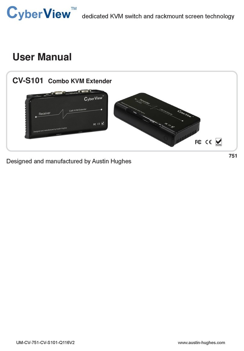
CV-S101Combo KVM Extender
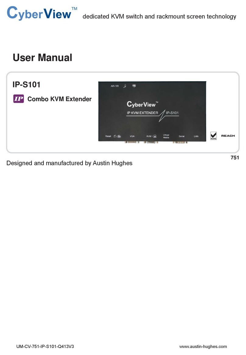
IP-101IP KVM Extender
Transmitter
Receiver

Chapter 1 Getting Started
1.1 Important Safeguards.............................................................................1
1.2 Regulatory Notice...................................................................................2
Part 1 CV-S101 Combo KVM extender
Chapter 2 Connection
2.1 Package Contents..................................................................................3
2.2 Transmitter LEDs, Button & Ports..........................................................4
2.3 Receiver LEDs, Button & Ports..............................................................5
2.4 Extending the KVM console port............................................................6
2.5 Extending the computer to the KVM port ..............................................7
2.6 Extending the computer..........................................................................8
2.7 Specifications.........................................................................................9
Chapter 3 KVM Extender Usage
3.1 Keyboard Hotkey command.................................................................10
3.2 Hot Plug................................................................................................10
Contents

Part 2 IP-101 IP KVM extender
Chapter 4 Connection
4.1 Package Contents.................................................................................11
4.2 Connection......................................................................................12-14
4.3 Connect to host system.........................................................................15
4.4 Connect to console side........................................................................16
4.5 Connect to multi-port KVM switch.........................................................17
4.6 Specifications........................................................................................18
Chapter 5 Configuration
5.1 Initial Configuration
5.1.1 Initial configuration via DHCP server...................................19-20
5.1.2 Initial configuration via serial console.......................................21
5.1.3 Keyboard, Mouse and Video configuration
5.1.3.1 IP-KVM switch keyboard settings..............................21
5.1.3.2 Remote Mouse Settings............................................22
5.1.3.3 Auto mouse speed and mouse synchronization.......22
5.1.3.4 Host system mouse settings................................22-23
5.1.3.5 Single and Double Mouse Mode...............................23
5.1.3.6 Recommended Mouse Setting..................................23
5.1.3.7 Video Modes.............................................................23
Chapter 6 Usage
6.1 Prerequisites.........................................................................................24
6.2 Login into the IP-KVM switch and logout
6.2.1 Login into the IP-KVM switch....................................................25
6.2.2 Logout from the IP-KVM switch................................................26
6.3 The Remote Console.............................................................................27
6.4 Main Window
6.4.1 Remote Console Control Bar...............................................28-33
6.4.2 Remote Console Status Line....................................................33

Chapter 7 Menu Options
7.1 Remote Control
7.1.1 KVM Console............................................................................34
7.1.2 Telnet Console.....................................................................34-35
7.2 Virtual Media
7.2.1 Floppy Disk...............................................................................36
7.2.2 CD ROM..............................................................................37-40
7.2.3 Drive redirection...................................................................41-44
7.2.4 Options.....................................................................................44
7.3 User Management
7.3.1 Change Password.....................................................................45
7.3.2 Users And Groups...............................................................45-46
7.4 KVM Settings
7.4.1 User Console.......................................................................46-48
7.4.2 Power Control......................................................................49-50
7.4.3 Keyboard/Mouse......................................................................51
7.4.4 Video........................................................................................51
7.5 Device Settings
7.5.1 Network...............................................................................51-52
7.5.2 Dynamic DNS......................................................................53-54
7.5.3 Security................................................................................54-55
7.5.4 Certificate............................................................................55-56
7.5.5 Serial Port............................................................................57-58
7.5.6 Date And Time..........................................................................58
7.5.7 Event Log............................................................................59-60
7.6 Maintenance
7.6.1 Device Information...............................................................60-61
7.6.2 Event Log.................................................................................61
7.6.3 UpdateFirmware..................................................................61-62
7.6.4 Unit Reset.................................................................................63
Chapter 8 FAQ.................................................................................................64

1.1 Important Safeguards Chapter 1
Please read all of these instructions carefully before you use the device. Save this manual for future
reference.
What the warranty does not cover
■Any product, on which the serial number has been defaced, modified or removed.
■Damage, deterioration or malfunction resulting from:
□Accident, misuse, neglect, fire, water, lightning, or other acts of nature, unauthorized product modifi-
cation, or failure to follow instructions supplied with the product.
□Repair or attempted repair by anyone not authorized by us.
□Any damage of the product due to shipment.
□Removal or installation of the product.
□Causes external to the product, such as electric power fluctuation or failure.
□Use of supplies or parts not meeting our specifications.
□Normal wear and tear.
□Any other causes which does not relate to a product defect.
■Removal, installation, and set-up service charges.
P. 1

1.2 Regulatory Notice Chapter 1
Legal Information
First English printing, October 2002
Information in this document has been carefully checked for accuracy; however, no guarantee is given to the
correctness of the contents. The information in this document is subject to change without notice. We are not
liable for any injury or loss that results from the use of this equipment.
Safety Instructions
■Unplug equipment before cleaning. Don’t use liquid or spray detergent; use a moist cloth.
■Keep equipment away from excessive humidity and heat. Preferably, keep it in an air-conditioned enviro-
nment with temperatures not exceeding 40º Celsius (104º Fahrenheit).
■When installing, place the equipment on a sturdy, level surface to prevent it from accidentally falling and
causing damage to other equipment or injury to persons nearby.
■When the drawer is in an open position, do not cover, block or in any way obstruct the gap between it and
the power supply. Proper air convection is necessary to keep it from overheating.
■Arrange the equipment’s power cord in such a way that others won’t trip or fall over it.
■If you are using a power cord that didn’t ship with the equipment, ensure that it is rated for the voltage
and current labeled on the equipment’s electrical ratings label. The voltage rating on the cord should be
higher than the one listed on the equipment’s ratings label.
■Observe all precautions and warnings attached to the equipment.
■If you don’t intend on using the equipment for a long time, disconnect it from the power outlet to prevent
being damaged by transient over-voltage.
■Keep all liquids away from the equipment to minimize the risk of accidental spillage. Liquid spilled on to
the power supply or on other hardware may cause damage, fire or electrical shock.
■Only qualified service personnel should open the chassis. Opening it yourself could damage the equip-
ment and invalidate its warranty.
■If any part of the equipment becomes damaged or stops functioning, have it checked by qualified service
personnel.
Regulatory Notices Federal Communications Commission (FCC)
This equipment has been tested and found to comply with the limits for a Class B digital device, pursuant to
Part 15 of the FCC rules. These limits are designed to provide reasonable protection against harmful interfer-
ence in a residential installation.
Any changes or modifications made to this equipment may void the user’s authority to operate this equip-
ment. This equipment generates, uses, and can radiate radio frequency energy and, if not installed and used
in accordance with the instructions, may cause harmful interference to radio communications.
However, there is no guarantee that interference will not occur in a particular installation. If this equipment
does cause harmful interference to radio or television reception, which can be determined by turning the
equipment off and on, the user is encouraged to try to correct the interference by one or more of the following
measures:
■Re-position or relocate the receiving antenna.
■Increase the separation between the equipment and receiver.
■Connect the equipment into an outlet on a circuit different from that to which the receiver is connected.
P. 2

2.1 Package Contents Chapter 2
P. 3
Transmitter x 1 pc
Receiver x 1 pc
User manual x 1 pc
Auto switch power adapter ( for receiver ) x 1 pc
CE-6 Combo 4-in-1 KVM cable x 1 pcs
4
2
1
3
User
Manual
1
2
4
3
5
5

Keyboard Mouse
Power
LED
Status
LED
Local
Computer
VGA Power
Front View Rear View
USB
Transmitter
Transmitter Box
Remote I/O
2.2 Transmitter LEDs, Button & Ports Chapter 2
P. 4
LED Status Description
Power
Off
The Transmitter is power off.
The Tramsmitter is connected to a computer which is power off.
On The Transmitter is power on and is connected to a computer which is power on.
Status
Off
The Transmitter host port is connected to a computer which is power on.
The computer connected to Transmitter’s host port is power on.
Flash
The Transmitter is occupied bt the remoter site (Receiver).
The Receiver is auto-adjusting the VGA signal.
The remote site (Receiver) is running the auto-detect (hotkey+A) function.
The Transmitter is linking with remoter when plugging/re-plugging in a CAT6 cable.
On The Transmitter is linked with the remoter site (Receiver) by a CAT6 cable.

Keyboard Mouse
Local Remote Local
Computer
VGA Power
Front View Rear View
USB
Receiver
Receiver Box
Remote I/O
2.3 Receiver LEDs, Button & Ports Chapter 2
Description
LED Status
Local Off The Local port is not selected.
On The Local port is selected and a computer connected to the Local port is power on.
Flash The Local port is selected, but no computer is connected to the Local port or the
computer is power off.
Remote Off The Remote port is not selected.
On The Remote port is selected and a computer connected to the Remote port is power
on.
Flash
The Remote port is selected, but no computer is connected to the Remote port or
the computer is power off.
The R-Box is auto-adjusting the VGA signal.
Button
Local For selecting local computer
Remote For selecting remote computer
P. 5
LED / Button

2.4 Extending the KVM console port up to 300m Chapter 2
Monitor
Cat6 cable
up to 300m
Console port
Monitor
* CE-6 cable
CE-6 cable
ReceiverTransmitter
P. 6
(Optional)
Caution : When connect to a KVM switch for extending the console port or KVM port, if the
default hotkey of KVM switch is “Scroll Lock + Scroll Lock”, please change the hotkey to oth-
ers, to avoid hotkey duplicate problem.

2.5 Extending the computer to the KVM port up to 300m Chapter 2
Cat6 cable
up to 300m
* CE-6 via USB server * CE-6 via PS/2 server
VGAKB MS
VGAUSB
Monitor
* CE-6 cable
P. 7
(Optional)
TransmitterReceiver
Cat5/6 KVM cable
PS/2 KVM cable
USB KVM cable
PS/2 to USB converter (SUN-31 kit)
+

2.6 Extending the computer up to 300m Chapter 2
Monitor
Cat6 cable
up to 300m
* CE-6 via USB server * CE-6 via PS/2 server
VGAKB MS
VGAUSB
Monitor
* CE-6 cable
* CE-6 cable
P. 8
(Optional)
ReceiverTransmitter

2.7 Specification Chapter 2
Item Description
Transmitter
USB Port Connect to USB keyboard and USB mouse
DB-15 Port DB-15 Port (Yellow) : Connect to Computer
DB-15 Port (Blue) : Connect to Monitor
RJ-45 Port (Cat6) Connect Cat6 cable to Receiver
LED’s 2 (Power and Data)
OSD Hotkey, Status
Keyboard Emulation USB
Mouse Emulation USB
VGA Resolution (Local Host) 1920 x 1440
Housing Metal
Operation Temperature 0 ~ 50 °C
Storage Temperature -20 ~ 60 °C
Humidity 0~80%, Non-Condensing
Dimension (mm) 158 x 71 x 30 mm
Weight (g) 370g
Receiver
USB Port Connect to USB keyboard and USB mouse
DB-15 Port DB-15 Port (Yellow) : Connect to Computer
DB-15 Port (Blue) : Connect to Monitor
RJ-45 Port (Cat6) Connect Cat6 cable to Transmitter
LED’s 2 (Local and Remote)
Port Selection Hotkey, Push Button
OSD Hotkey, Status
Keyboard Emulation USB
Mouse Emulation USB
VGA Resolution (Local Host) 1920 x 1440
VGA Resolution (Remote Host) 1680 x 1050 (500 ft)
1024 x 768 (1000 ft)
Housing Metal
Power Adapter DC 12V, 1A
Operation Temperature 0 ~ 50 °C
Storage Temperature -20 ~ 60 °C
Humidity 0~80%, Non-Condensing
Dimension (mm) 158 x 71 x 30 mm
Weight (g) 370g
P. 9

3.1 Keyboard Hotkey Commands Chapter 3
Command Function
CTo switch between Local and Remote ports
QTo turn the beep sound on or off
STo activate the Auto-Scan function. Auto-scan Remote
and Local port every 8 seconds repeatedly.
AFor auto-adjust video signal of remote port to optimum
You can switch the Receiver from “Local Host” port to “RJ-45” port and vice-versa through simple key se-
quences made by the remote console side. To send commands to the Receiver, you must press the hotkey
(default is Scroll Lock) twice within 2 seconds. You will hear a beep sound confirming you are in the hotkey
mode. If you do not press any key during hotkey mode over 2 seconds the hotkey mode will be terminated
and back to normal state.
The default hotkey is Scroll Lock but you can change hotkey as your application convenience. If you prefer to
use other hotkey, please go to OSD menu and change the default hotkey to the other.
P.10
Example:
The table blow lists all the supported hotkey commands.
When the transmitter is connected to a KVM Switch, the hotkey commands of the KVM switch will be passed
to KVM Switch directly.
The KVM Cat6 extender supports “Hot Plug” function for easy addition or removal of PCs. You can
arrange or maintain PCs as follows:
■PC can be disconnected and reconnected to the same or different port of the KVM unit without having to power it
off as long as it is not the delay-chain port or pass through port.
■The pass through port PC (i.e. the PC is connecting to the console port directly) is powered on. Before you hot plug
devices, please switch from this pass through port to next port, and then switch back to the pass through port.
■You may unplug the mouse or the keyboard from the console port and plug it back in at any time.
3.2 Hot Plug
Caution : Some OS (Operation Systems) like SCO Unix is unable to support “Hot Plug” func-
tion. If you “Hot Plug” to this kind of OS, it will cause unpredictable behavior or shut down the
PC. Before “Hot Plug”, please make sure your OS and software driver supports it.
Scroll
Lock Scroll
Lock

4.1 Package Contents Chapter 4
P. 11
IP-101 x 1 pc
User manual x 1 pc
Power cord x 1 pc
5V auto switch power adapter x 1 pc
CA-6 PS/2 KVM cascade cable x 1 pc
4
2
1
3
User
Manual
1
2
4
3
5
5
IP KVMEXTENDER IP-101

VGA
Mouse
USB Power LAN Serial
Keyboard
Host Console
PS/2
Mouse
4.2 Connection Chapter 4
P.12
IP KVM EXTENDER IP-101
PS/2
VGA
Keyboard
Reset
Please perform the following steps:
1. Connect the power supply to IP-KVM switch
2. Connect the monitor to the IP-KVM switch console side.
3. Connect the keyboard to the IP-KVM switch console side.
4. Connect the mouse to the IP-KVM switch console side.
5. Connect a VGA cable (15-pin HDDB Male / Male) with the Male side to both of the PC and the host port of
the IP-KVM switch.
6. Connect one purple end of 3-in-one cable to the PS/2 mouse port on the computer, and the other end of
3-in-one cable to the host PS/2 mouse port on the IP-KVM Switch.
7. Connect one green end of 3-in-one cable to PS/2 keyboard port on the computer, and the other end of
3-in-one cable to the host PS/2 keyboard port on the IP-KVM switch.
8. Connect the type A connector of USB A-B cable to the host system, while using remote mass storage
control.
9. Connect Ethernet to LAN port and/or modem to DB-9 serial port, depending on how you want to access
IP-KVM switch

P.13
4.2 Connection Chapter 4
Video modes
IP-KVM switch recognizes a limited number of common video modes. When running X-Window on the host
system, please don’t use any custom mode lines with special video modes. If done so, IP-KVM switch may
not be able to detect these. You are on the safe side with all standard VESA video modes.
Please refer to Appendix C for a list of all known modes.
Initial IP configuration
Initially the IP-KVM switch network interface is configured with the parameters shown in the following table.
If this initial configuration doesn’t meet your local requirements, you need to do the initial IP configuration.
Use one of the following ways:
1. Connect the enclosed NULL modem cable to the serial interface on the rear side. The serial interface
needs to be adjusted with the parameters shown in the following table:
Use a terminal software (e.g. hyper term or minicom) to connect to IP-KVM switch. Reset IP-KVM switch and
immediately press < ESC >. You will see some device information and a ’=>’ prompt.
Enter the command ’config’ and press < Enter >. After waiting a few moments you may configure IP auto
configuration, IP address, net mask and default gateway. Pressing < Enter > without entering values does
not change settings. The gateway value must be set to 0.0.0.0 (for no gateway) or any other value. You will
be asked if the values are correct and get a chance to correct them. After confirming, IP-KVM switch per-
forms a reset.
2. Use a crossover Ethernet cable to connect IP-KVM switch to a subnet where a DHCP server is available.
After the DHCP server has assigned an IP address to IP-KVM switch you can use the web interface to
configure the device.
Web interface
IP-KVM switch may be accessed using a standard JAVA enabled web browser. You may use the HTTP pro-
tocol or a secure encrypted connection via HTTPS. Just enter the configured IP address of IP-KVM switch
into your web browser.
Parameter Value
IP auto configuration DHCP
IP-Address 192.168.1.22
Net-mask 255.255.255.0
Default-Gateway none
Parameter Value
Bits/second 115200
Data bits 8
Parity No
Stop bits 1
Flow Control None
Login name super (factory default)
Password pass (factory default)

P.14
4.2 Connection Chapter 4
Changing these settings to user specific values is strongly recommended
and can be done on the User Management page
Remote Console
The Remote Console is the redirected screen, keyboard and mouse of the remote host system to which IP-
KVM switch is installed. The web browser which is used for accessing IP-KVM switch has to supply a Java
Runtime Environment version 1.1 or higher. However, it is strongly recommended to install Sun JVM 1.4. The
Remote Console will behave exactly the same way as if you were sitting directly in front of the screen of your
remote system. That means that both the keyboard and mouse can be used in the usual way. Open the con-
sole by selecting the preview picture on the main site of the HTML front end. The following diagram shows
the top of the Remote Console.
There are some options to choose from, and the important ones are the following:
Auto Adjust button
If the video displayed is of bad quality or distorted in some way, press this button and wait a few seconds
while IP-KVM switch tries to adjust itself for the best possible video quality.
Sync Mouse
Choose this option in order to synchronize the local with the remote mouse cursor. This is especially nec-
essary when using accelerated mouse settings on the host system. In general there is no need to change
mouse settings on the host.
Video Settings in Options Menu This opens a new window with elements to control the IP-KVM switch Video
Settings. You can change some values, for instance the brightness and contrast of the picture displayed,
which may improve the video quality. It is also possible to revert to the default settings for all video modes or
only the current one.
Note: At first start, if the local mouse pointer is not synchronized with the remote mouse pointer, press the
Auto Adjust Button once.

4.3 Connect to Host System Chapter 4
P.15
(Optional)
Remark:
■Optional: Connect the type A connector of USB A-B cable to the USB of the host system, while using
remote mass storage control. USB type A plug of USB A-B cable to the computer.
CA-6

4.4 Connect to Console Side Chapter 4
P.16
Remark:
The rear side of IP-KVM switch provides a RJ-45 connector for Ethernet. The connector is used either for a
100 Mbps 100BASE-TX connection or for a 10 Mbps 10BASE-T connection. The adapter can sense the con-
nection speed and will adjust to the appropriate operation mode automatically.
10 Mbps Connection
For 10BASE-T Ethernet networks, the Ethernet adapter uses Category 3, 4, 5 or 6 UTP cable. To establish a
10 Mbps connection, the cable must be connected to a 10BASE-T hub.
■Make sure that the cable is wired appropriately for a standard 10BASE-T adapter.
■Align the RJ-45 plug with the notch on the adapter’s connector and insert it into the adapter’s connector.
100 Mbps Connection
For 100BASE-TX Fast Ethernet networks, IP-KVM switch supports Category 5 or 6 UTP cabling. To establish
a 100 Mbps connection, the cable must be connected to a 100BASE-TX hub.
■Make sure that the cable is wired appropriately for a standard 100BASE-TX adapter.
■Align the RJ-45 plug with the notch on the adapter’s connector and insert it into the adapter’s connector.
Monitor
Other manuals for CV-S101
2
This manual suits for next models
1
Table of contents
Other CyberView Extender manuals