CYBEX 625T User manual

Page 1 of 7 www.cybexintl.com
Apple iPod, iPhone Upgrade Kit 625T
Kit Number KAX-25113 Installation Instructions
This instruction sheet describes how to install the Apple upgrade kit for Cybex treadmill model 625T.
Tools Required
• Phillips screwdriver
• Utility knife
• ESD (Electrostatic Discharge) grounding strap
Read and understand all instructions thoroughly before installing this kit.
Verify the kit contents shown.
1
23
4
5
6
8
7
Description Qty.
1iPod assembly,
AX-24137
1
2Screw, 6-19 x 0.50”,
HS-18320
4
3Decal, Headphone
jack, DE-22784
1
4Cable, Ground,
AW-22357
1
5Cable, GFX to MCC,
AW-22537
1
6Cable, iPod, 30 pin,
AW-22697
1
7Cable, Headphone
jack, AW-22480
1
8Cover, iPod access,
PL-24244
1

Page 2 of 7 www.cybexintl.com
Disconnect power source
Unplug the power cord from the power outlet.
WARNING: Shock and electrocution hazard
• Unplug unit and let sit 10 minutes before cleaning or performing maintenance
• Electrical charge can remain in unit after unplugging
• Keep water and liquids away from electrical parts
NOTICE: Component damage
Wear an ESD grounding strap during this procedure. Connect ESD grounding strap to
frame bolts or unpainted metal of frame. If ESD grounding strap is not available, touch
frame bolts or unpainted metal of frame before handling any electronics.
Remove back cover
Remove the four screws securing the back cover to the console assembly using a Phillips
screwdriver.
3
2
1
Description Qty
1Console Assembly 1
2Back Cover 1
3Screws 4
Remove access cover
1. Remove the two screws securing the access cover to the handset using a Phillips screwdriver.
A/V models
3
2
4
5
1
Description Qty
1Connector J6 1
2Headphone Jack Cable 1
3Headphone Jack Cover 1
4Screws 2
5Handset 1

Page 3 of 7 www.cybexintl.com
2. Unplug the headphone jack cable carefully from the connector J6 on the MCC board
(connector on right). Pull connector straight out, cable uses a 90 degree connector.
Non A/V models
Remove the two screws securing the access cover to the handset using a Phillips screwdriver.
12
3
Description Qty
1Access Cover 1
2Screws 2
3Handset 1
Remove handset assembly
1. Remove the eight screws securing the handset to the console using a Phillips screwdriver.
3
12
Description Qty
1Handset Assembly 1
2Console 1
3Screws 8
Use ashlight to locate cable connectors.
2. Unplug cables by pinching latch and make sure it releases connector. Pull connector out.
Latch Pull Straight Out
From Connector
DO NOT PULL
CONNECTOR OUT
BY THE WIRES!

Page 4 of 7 www.cybexintl.com
3. Lift the handset assembly carefully and unplug the following cables: contact heart rate grips
(J7), and handset membrane (J9).
12
Description Qty
1Handset Membrane (J9) 1
2Contact Heart Rate Grips (J7) 1
Install access cover
1. Remove the two screws securing the access cover to the handset using a Phillips screwdriver.
2
1
3
Description Qty
1Handset 1
2Screw 2
3Access Cover 1
2. Install the two screws securing the new access cover to the handset using a Phillips
screwdriver.
Install iPod board
1. Install the iPod board, four screws, and ground wire as shown using a Phillips screwdriver.
1
2
3
4
Description Qty
1Handset 1
2Screws 2
3Access Cover 1

Page 5 of 7 www.cybexintl.com
2. Plug the GFX to MCC cable into the iPod board.
Install headphone jack cable (non A/V units)
1. Remove the blank decal from the headphone jack cover using a utility knife.
2. Install the headphone jack decal on the headphone jack cover.
3. Install the nut into the front of the headphone jack cover.
1
3
2
Description Qty
1Headphone Jack Cover 1
2Nut 1
3Headphone Jack Cable 1
4. Screw the headphone jack cable into the headphone jack cover and tighten by hand.
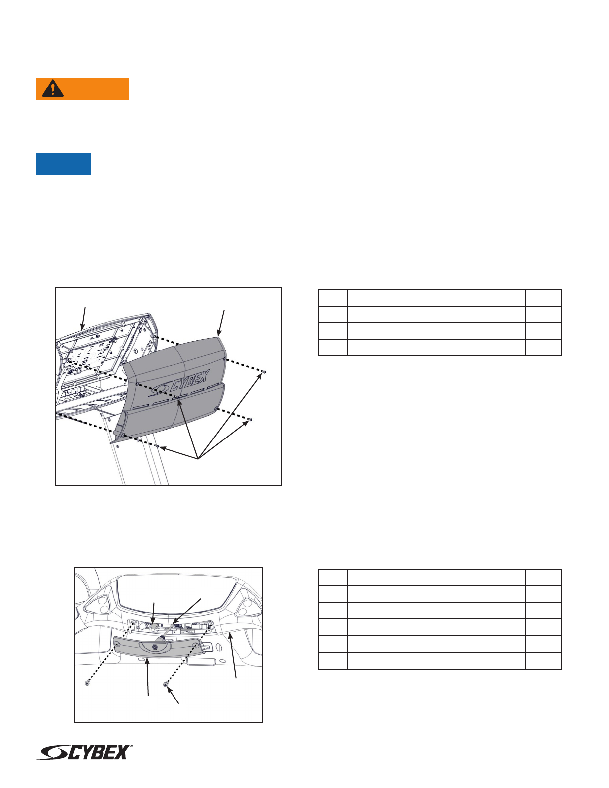
Install handset assembly
1. Place the handset assembly in position and plug in the following cables: iPod board (J12),
ground wire, handset membrane (J9), and contact heart rate grips (J7).
1
3
2
4
Description Qty
1iPod Board (J12) (under cover) 1
2Ground wire 1
3Handset Membrane (J9) 1
4Contact Heart Rate Grips (J7) 1
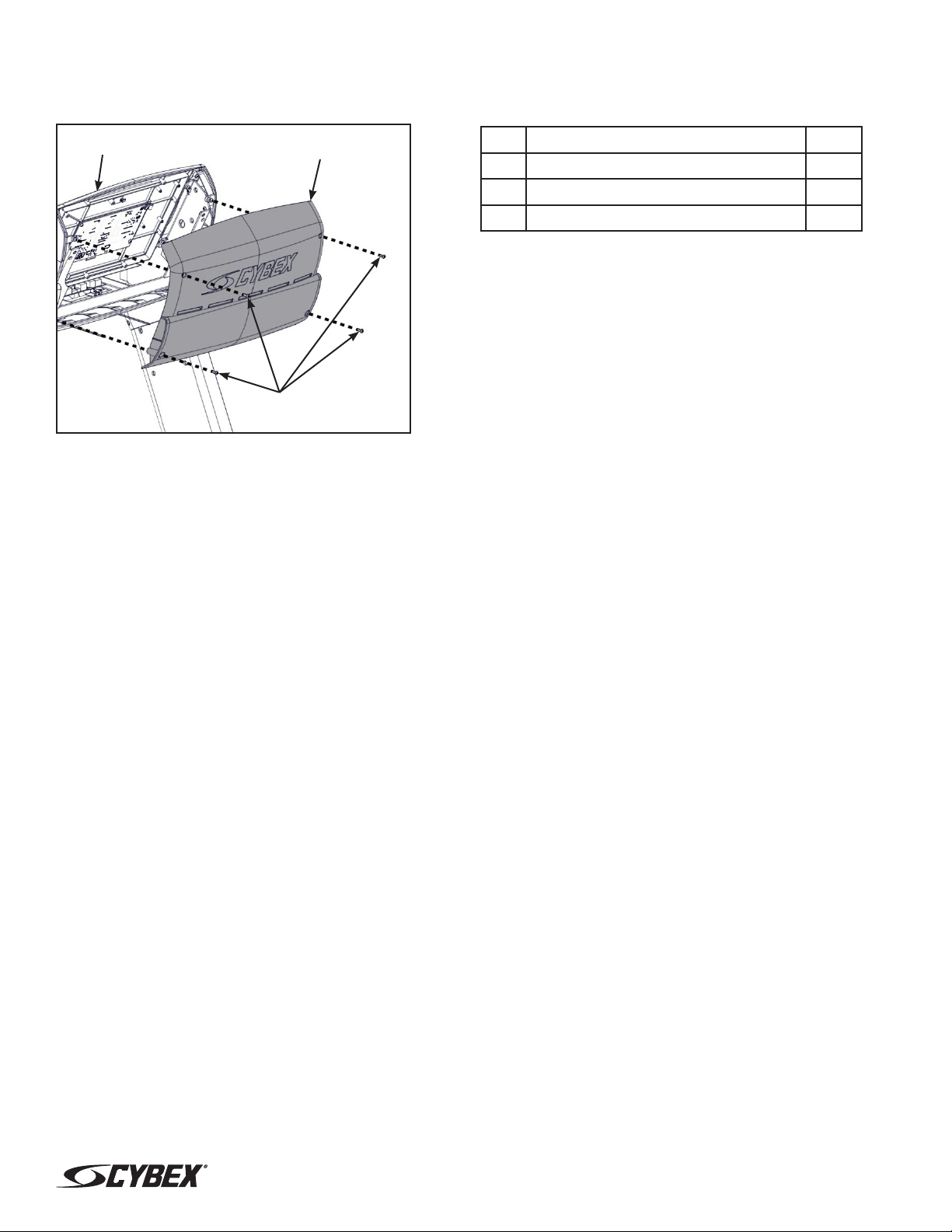
2. Insert the strain relief of the iPod cable into the notch in the access cover.
1
2
Description Qty
1iPod cable strain relief 1
2Access cover notch 1

Page 6 of 7 www.cybexintl.com
3. Install the eight screws securing the handset assembly to the console using a Phillips
screwdriver.
3
12
Description Qty
1Handset Assembly 1
2Console 1
3Screws 8
Install handset cover
1. Plug the headphone jack cable into the connector J6.
3
2
4
5
1
Description Qty
1Connector J6 1
2Headphone Jack Cable 1
3Headphone Jack Cover 1
4Screws 2
5Handset 1
2. Install the two screws securing the headphone jack cover to the handset cover using a Phillips
screwdriver.

Cybex® and the Cybex logo are registered trademarks of Cybex International, Inc.
iPod, iPhone, and iPad are trademarks of Apple Inc., registered in the U.S. and other countries.
10 Trotter Drive Medway, MA 02053
508-533-4300 • FAX 508-533-5183 • www.cybexintl.com
Copyright © 2014, Cybex International, Inc. All rights reserved • LT-25115-4 A • July 2014
Page 7 of 7 www.cybexintl.com
Install back cover
Install the four screws securing the back cover to the console assembly using a Phillips screwdriver.
3
2
1
Description Qty
1Console Assembly 1
2Back Cover 1
3Screws 4
Complete installation
1. Verify the power cord is not being pinched under the front of the treadmill.
2. Plug the power cord into the power outlet.
3. Toggle the power switch on (I).
4. Operate the unit at all levels to verify proper operation.
Other manuals for 625T
4
This manual suits for next models
1
Table of contents