Operating Instructions | GPM 450 verSA
4
If the GPM 450 verSA is used correctly, it is a very safe machine. However, if used incorrectly, it can
be dangerous. When operating the machine, the operator is responsible for their own personal
safety. The manufacturer may not be held liable for any personal injury or damage to the machine
caused by use or operation at variance with these Operating Instructions. The owner of the machine
is responsible for the machine being operated, maintained and serviced only by qualified personnel.
The machine design is in compliance with international standards and regulations for the
construction of machine tools. For the machines exported to the European Economic Area (EEA), the
customer will obtain a "Declaration of Conformity" together with the accompanying technical
documentation for the machine - Operating Instructions. Also, the machine bears the CE marking.
The CE marking on the machinery signifies that the product complies with the technical requirements
specified in all the legal regulations that apply to the machinery and that require or allow this
marking. This marking also signifies that a specified procedure was followed during the assessment of
the stated conformity.
The manufacturer certifies by means of the “Declaration of Conformity” that the machinery
concerned complies with the requirements of Directive 98/37/CE of the European Parliament and of
the Council and those of the harmonized technical standards. Directive 98/37/CE of the European
Parliament and of the Council is a document defining the generally applicable basic requirements for
health protection and safety of machinery operated at the user’s facility within the EEA.
Directive 98/37/CE of the European Parliament and of the Council does not apply to the machinery
exported to countries outside the EEA.
The customer will receive the accompanying technical documentation for the machine –Operating
Instructions. The manufacturer hereby requests that the user trains its staff accordingly in order to
ensure comprehensive safety as directed by the relevant laws, standards and regulations, these
Operating Instructions and other documents.
The machine is intended for work in automatic cycles.
The machine operator monitors the process and the operating mode of the machine, replacing
material and checking the dimensions. The Operator's position by the machine is not defined.
3. WARNINGS AND RECOMMENDATIONS
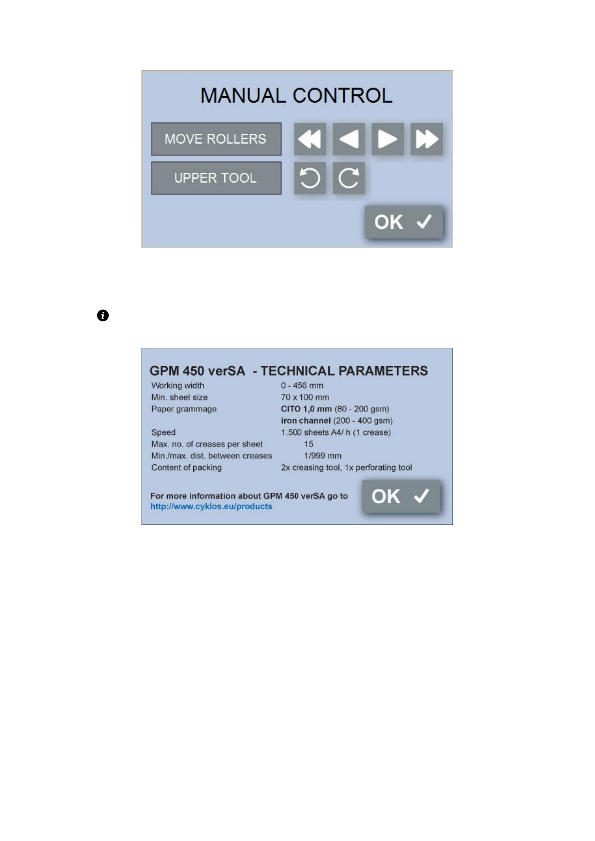
Only sheets of the size listed in the parameters can be creased, perforated and punched by GPM 450
verSA.
a) The operator or the individual appointed for operation cannot use the machine unless they
have been trained.
b) Only sheets of the size listed in the parameters can be creased, perforated and punched by
GPM 450 verSA.
c) It is forbidden to crease and perforate foils, sheet metal or other similar materials.
d) The machine can be only used in interior spaces (e.g. offices, shops), it is not allowed to use
the machine outdoors.