1. Kit Contents
Each CY3280-BSM Universal CapSense™ Simple Button Module Kit contains:
■CY3280-BSM Universal CapSense Module Board
■CY3280-BSM Universal CapSense Module Board CD/DVD
■CY3280-BSM Quick Start
■3 mm Acrylic Overlay with adhesive
■1.5 mm Acrylic Overlay with adhesive
Universal CapSense Module boards are available for purchase separately, or as part
of combination kits. Do visit www.cypress.com/shop for more information.
Prerequisites:
■Universal CapSense Controller Board
■PSoC MiniProg
■I2CUSB Bridge
■USB Mini-B Cable
2. Module Hardware
This module is comprised of components and sensors detailed in the following figure.
The module consist of ten CapSense buttons and ten LEDs. These are interfaced to
the CapSense controller board via 44 pin receptacle connector (J1). A three pin jumper
(J2) is provided for selection between shield electrode and ground. The board also
incorporates an optional I2C EEPROM and thermistor that are not populated by
default.
Optional I2C EEPROM
Footprint (On Reverse Side) Voltage Test Points
44 Pin CapSense
Connector (J1)
Optional Thermistor
Footprint
(On Reverse Side)
Shield
Selection
Jumper (J2)
CapSense
Buttons and
LEDs
Page 2 Page 3
3. Getting Started
The CY3280-BSM board can be used with any of the UCC (Universal CapSense
controller) boards. The example firmware is available on the CD/DVD. Insert the
CY3280-BSM Kit CD/DVD into the CD/DVD drive of your PC, and follow the
instructions on the screen to complete the installation.
4. Setup the Board
This section demonstrates the setup of CY3280-BSM with CY3280-20x34 Universal
CapSense Controller. Similar procedure is used for all UCC boards.
■Connect the CY3280-BSM board to the CY3280-20x34 Universal CapSense
Controller board's P2 receptacle connector.
■In CY3280-20x34 UCC board place shunts on pins 2 and 3 of J1 and pins 1 and 2
of J4.
■In CY3280-BSM board place shunts on pins 2 and 3 of J2.
■Connect your computer to the CY3280-20x34 Universal CapSense Controller
board's ISSP connector (J3) using a PSoC MiniProg and a USB cable.
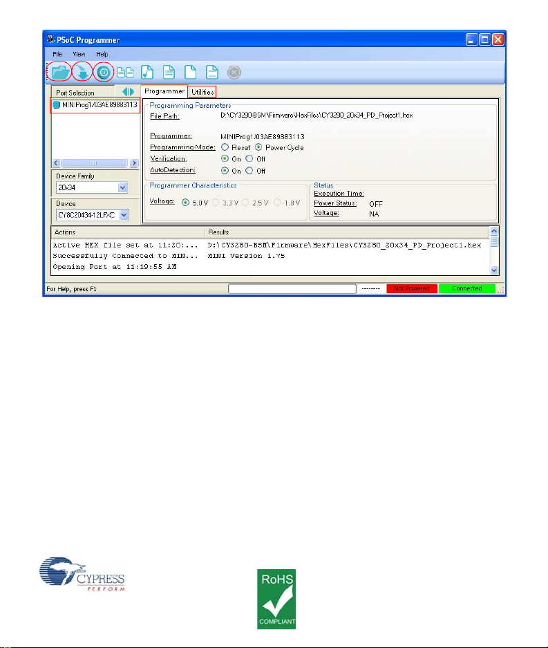
■Open PSoC Programmer by going to Windows Start > All Programs >
Cypress > PSoC Programming 3.05 > PSoC Programmer.
■Select MiniProg 1 from Port Selection view in the Programmer window.
■Message Successfully Connected to MINIProg…..MINI Version 1.75 appears in
the Actions pane.
Note: If MiniProg Version is older than 1.75, go to Utilities and click on Update
Firmware icon.
■Confirm that the Programming Parameters are as shown in the figure on page 4.
■Click File Load, navigate to, and open the CY3280_20x34_PD_Project1.hex file
on CD/DVD at: Firmware\HexFiles
■Click the Program icon. After the programming is complete Programming
Succeeded appears in the Actions pane.
■Click Toggle Device Power button. The Power LEDs D1, D2 on the CY3280-
20x34 UCC board lights up. Corresponding LEDs on other UCC board's lights up.
[+] Feedback