Cytech UCM/Modbus User manual

UCM/Modbus Quick Start Guide
INTRODUCTION
The UCM/Modbus allows Modbus devices to be interfaced to Cytech's Comfort
system. The UCM/Modbus can be programmed either as a Modbus Master or Slave.
Master mode is for Comfort to control other Modbus Slave products, and Slave
mode is for a Modbus Master to control Comfort, eg software. oth modes are
capable of 2- way communications, ie Comfort to Modbus and Modbus to Comfort,
Modbus/RTU (RS485 or RS232) and Modbus/TCP are possible by plugging in the
RS485, Rs232 or ETH03 Ethernet submodule onto the UCM/Modbus baseboard.
The UCM/Modbus can work with other Comfort modules including Intelligent
Remote Input/Output Modules (IRIO), MSM01 Multisensor Module, Hotel I/O (HIO)
as well as 3rd party systems on the Comfort us including C- us allowing Modbus to
be integrated with other 3rd party products.
Specifications
•Modbus Master or Slave Mode
•Physical Interfaces Modbus/RTU (for RS485) using RS485 submodule and
Modbus/TCP using ETH03 submodule.
•Comfort (CM9001), UCM/Logic, LGX01 Logic Engine can act as the central controller
for UCM/Modbus.
•For Master Mode: 256 Modbus addresses in Modbus to Comfort. Different Modbus
IDs can be specified for each Modbus Address
•For Modbus Slave, supported Function codes are; Read Discrete Inputs, Read Coils,
Read Input Registers, Read Holding Registers, Write Single Coil, Write Single Holding
1

UCM/Modbus Quick Start Guide
Register.
•For Modbus over RS485, baud rate selectable from 1200, 2400, 4800, 9600, 19200,
38400, 76800 bps. For Modbus/TCP, baud rate is not used.
Minimum System Requirements
•Comfort Ultra/OPT, UCM/Logic, KNX/LOG LGX01 Firmware 7.116 or above
•UCM/Modbus firmware 7.163 or above
•Comfigurator 3.13.7.2 or above
Setup
The package includes
•UCM/Modbus-485 with RS485 Submodule; or
•UCM/Modbus-ETH03 with ETH03 submodule (Universal)
•4 wire white RS485 cable
•4 standoffs for enclosure
UCM ID Settings by DIP Switch
SW7 DIP Switch (RS485 ID Primary) - Comfort is able to s pport p to 8 UCMs. SW7 is a set of 4 DIP
Switches which determines the UCM ID, according to the table below:
ID DIP -1 DIP - 2 DIP - 3 DIP - 4
1 ON ON ON ON
2 OFF ON ON ON
3 ON OFF ON ON
4 OFF OFF ON ON
5 ON ON OFF ON
6 OFF ON OFF ON
7 ON OFF OFF ON
8 OFF OFF OFF ON
y convention, UCM ID=1 is used for Comfigurator. The UCM/Modbus should be set
to ID 2 or above so that any RS485 communications failure can be reported by
Comfort. Press RESET on the UCM after changing the ID settings.
UCM ID Setting using COPY Switch ( lternative)
The UCM ID can also be changed by use of the COPY switch. If SW7 1 to 4 are all
OFF, then the UCM ID is determined by the saved setting in the U2 EEPROM.
Pressing the COPY button momentarily will show the ID on its LEDS as shown
below (in binary code)
ID ERR (D4) BUSY2 (D3) BUSY1 (D2) RDY (D1)
1 Off Off Off On
2 Off Off On Off
3 Off Off On On
4 Off On Off Off
5 Off On Off On
6 Off On On Off
7 Off On On On
8 On Off Off Off
Unassigned On On On On
To change the UCM ID assignment, press and hold the COPY button for at least 2
seconds. The UCM ID will be incremented to the next higher number up to 8. Press
and release the COPY button to increment the ID until the desired ID is seen. If the
2

UCM/Modbus Quick Start Guide
COPY button is not pressed for 4 seconds, the ID is confirmed and the UCM is reset
causing all the LEDs to momentarily turn on. This setting only works if the U2
EEPROM is present and the SW7 DIP switches are all off.
If the ID is unassigned, all LEDS are ON.
The Number of UCMs in Comfigurator Modules and Settings should be set according
to the number of UCMs connected. This is automatically done by a Scan for
Modules. Up to 8 UCMs can be connected to the Comfort network.
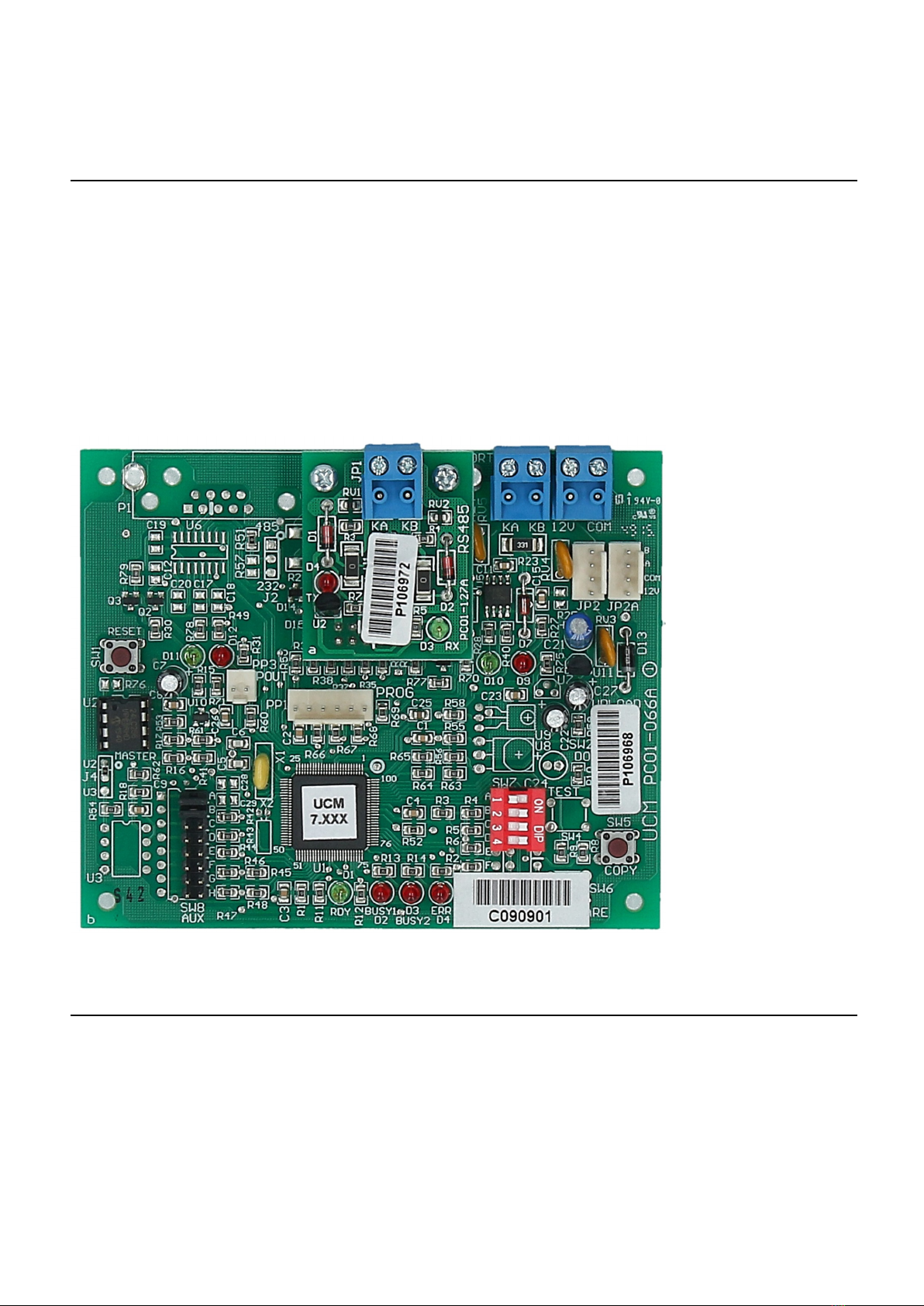
Buttons
•SW1 – RESET. This b tton resets the UCM/Modb s. It does not change any parameters in
Comfort or UCM/Modb s.
LED Indicators on UCM
•D1 “RDY” (Green) sho ld be on at all times.
•D2 “BUSY1” (Red) Not Used
•D3 “BUSY2” (Red) Not Used
•D4 “ERROR” (Red) Not Used
•D9 (Red) RS485 Transmit to Comfort
•D10 (Green) RS485 Receive from Comfort
•D11 (Green) Receive Data from Modb s
•D12 (Red) Transmit Data to Modb s
Connection Procedure
•Before connecting the UCM to Comfort, set the UCM/Modb s ID to the ID of the UCM
according to the instr ctions in the previo s section.
•The UCM is connected to Comfort via the s pplied 4-way white cable from 4-pin header JP2 to
CM9001 RS485 header. This s pplies power to the UCM, as well as allowing comm nications
between Comfort and the UCM. It is not necessary to switch off the power to Comfort before
pl gging in this connection.
•Connect the UCM/Modb s to the Modb s network as follows;
•For Modb s/RTU by RS485, the RS485 s bmod le on UCM/Modb s sho ld be pl gged in. KA
and KB on the RS485 s bmod le sho ld be connected to the Modb s RS485 network.
•For Modb s/TCP, the ETH03 s bmod le sho ld be pl gged in. The ETH03 LAN port sho ld be
connected to the Local Area network via a H b or switch.
•When the UCM/Modb s is connected to Comfort, the Green RDY led on the UCM (D1) sho ld
light p and remain on. The LEDs D9 (red) and D10 (green) sho ld blink rapidly showing that
RS485 comm nications has been established between Comfort and the UCM. D9 (green) flashing
shows that it is receiving comm nications from Comfort (poll). D10 (red) comes on when the
UCM responds to a poll from Comfort. D12 (RED) sho ld blink when a message is sent to
Modb s. D11 (green) sho ld blink when a message is received from Modb s.
•In Modb s Master Mode, the D12 (red) LED sho ld blink when the UCM/Modb s polls the
Slave, and D11 (Green) led sho ld blink when there is a reply to the poll. If all polls are replied,
the D11 and D12 leds sho ld blink fast. If only D12 (red) led blinks and D11 (gree) remains off,
that means the Modb s slave does not reply to the poll from UCM/Modb s
•In Modb s Slave Mode, the Modb s Master will poll the UCM/Modb s reg larly, at an interval
depending on the Master. The UCM/Modb s Slave sho ld always reply to a valid poll to the
correct ID.
3

UCM/Modbus Quick Start Guide
CONFIGURATION
Please download UCM/Modb s Programming Man al from http://www.cytech.biz/ cmmodb s-485.html
Document History
26 August 2022 -Separated UCM/Mosbus Manual into Quick start Guide and
Programmming Manual
Size A6 ooklet
4
Table of contents
Other Cytech Recording Equipment manuals