D'Alessandro Termomeccanica CS Small 20 User guide

C.da Cerreto, 55 - 66010 MIGLIANICO (CH) – Italy Tel. (+39) 0871/950329 Fax (+39) 0871/950687
http://www.caldaiedalessandro.it e-mail: info@caldaiedalessandro.it
Wood biomass heat generator
Series CS SMALL
Models from 20 to 100
USE AND MAINTENANCE GUIDE
Ver. 1.0 - QCSSMALLXIT0114

2
Flue
The flue represents one of the fundamental elements of the heat generator.
The correct designing of the fumes evacuation system guarantees the correct
and always efficient generator functioning and prevents the potentially dangerous
situations for the user.
For a correct installation, refer to section 6.5 pag.17 of this manual and, however,
use experienced staff.
Fire—resistant
It is essential for the first ignition to be gradual without bringing the genera-
tor to maximum temperature, to avoid the fire-resistant material inside the com-
bustion chamber from being damaged. Re-start the generator and bring it to ma-
ximum temperature and, therefore, at normal functioning only after cooling.

3
Electrical connections
The generator is equipped with a main switch not automatic ISOLATOR type.
It is recommended to protect the power supply line using a differential magne-
tothermic switch.
Refer to the attached control board manual for electrical connections.

4
CONTENTS
1GENERAL INFORMATION 6
1.1 Identification and purpose of the document 6
1.2 Technical data plate 6
1.3 CE Marking 6
1.4 Reference standards 7
1.5 Typographic Conventions 7
1.6 Guarantee and Responsability 7
2SAFETY AND RESIDUAL RISKS 8
2.1 Risks connected to the use of the machine 8
2.2 Residual risks 8
2.3 Intended use of generator 9
2.4 Improper use of generator 9
3FUNCTIONING, TECHNICAL FEATURES AND DIMENSIONS 10
3.1 Generator operation illustration 10
3.2 Generator operation description 10
3.3 Technical features 11
3.4 List of components and spare parts 12
3.5 General dimensions 13
3.6 Hydraulic connections 13
4FUELS 14
4.1 Usable fuels 14
4.2 Other fuels 14
5TRANSPORT AND HANDLING 14
5.1 General information 14
5.2 Transport and handling 14
6INSTALLATION AND TESTING 16
6.1 General installation requirements 16
6.2 Installer requirements ( Italy ) 16
6.3 Installer requirements ( Other countries ) 16
6.4 Place of installation 16
6.5 Flue and draught 17
6.6 Electrical system and connections 18
6.7 Final testing 18
7POWER ON, START-UP AND CHECKING 19
7.1 Checks prior to start-up 19
7.2 Start-up 19
7.3 Normal operation 20

5
7.4 Frequent heat request condition 20
7.5 Carburation 20
7.6 Comburent air regulation 20
7.7 Fuel regulation 21
7.8 Switch off 21
8CLEANING 22
8.1 General information 22
9MAINTENANCE 24
9.1 General information 24
10 ANOMALIES, FAILURES AND MALFUNCTIONS, questions and an-
swers
25
10.1 Table of anomalies and failures 25
10.2 Table of malfunctions 26
11 NOISE 26
11.1 General information 26
11.2 Sound emission value 26
12 DECOMMISSIONING AND SCRAPPING 26
12.1 General information 26
12.2 Scrapping 26
CCOPY OF DECLARATION OF CONFORMITY 28
DCOPY OF PARTIAL SWITCHING OFF DECLARATION 29

6
1. GENERAL INFORMATION
1.1 Identification and purpose of the document
This instruction guide drafted by D’ALESSANDRO TERMOMECCANICA is an integral part of the
heat generator. Any reproduction, even partial, is prohibited.
The aim of this manual is to provide all the necessary information for a correct use guaranteeing
maximum safety for people, animals and objects.
The company D’Alessandro Termomeccanica is clearly indicated as Manufacturer, in compliance
with Directive 2006/42 EEC, by means of the following documents:
Declaration of conformity
CE Marking
Use and maintenance guide
The legal name of the manufacturer is:
D'Alessandro Termomeccanica - C.da Cerreto 55
66016 Miglianico (CH) - Italia
As displayed on the identification plate on the left panel of the generator with the CE marking.
1.2 Identification plate
The plate installed on the generator displays the legal name of the manufacturer together with the
following details:
Year of manufacture
Series
model
Serial number
Nominal power
Maximum working pressure
Maximum working temperature
Water content
Empty weight
Power consumption
Mains voltage
1.3 CE marking
The plate with the legal name of the manufacturer, the machine identification data, the CE mar-
king and the declaration of conformità enclosed certify that the machine complies with the appli-
cable European Directives.

7
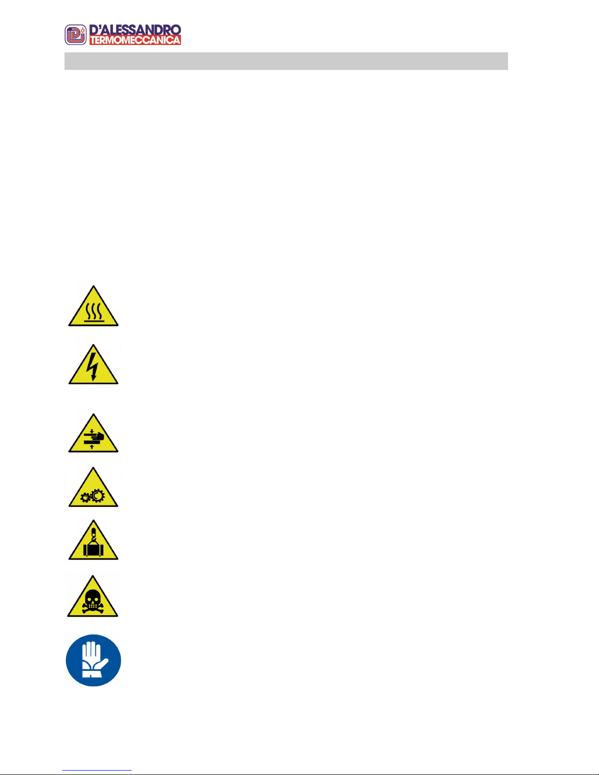
1.5 Typographic Comventions
Special attention must be paid to the parts of this user guide marked with the symbols listed be-
low:
IMPORTANT
DANGER
MANDATORY
PROHIBITED
1.6 Guarantee and liability
The guarantee refers to both the mechanical and electrical parts of the generator, in compliance
with the European Directive 1999/44/EC, which protects the user against construction defects for
a period of two years.
The guarantee is void in case of damages due to:
Transport and/or handling (if charged to the customer);
Assembly errors by the installer;
Failure to comply with the maintenance and cleaning instructions described in this manual;
Failures and/or breaks not due to the malfunction of the machine itself;
Reasons not due to the manufacturer
The guarantee is valid only for the original customer and only when he/she becomes exclusive
owner of the machine.
Any controversy between D’Alessandro Termomeccanica and the purchaser are settled by arbi-
tration; in case of non-agreement upon the arbitration board, the place of jurisdiction shall be
Chieti. The aforementioned points are contained in the general conditions of sale, which are an
integrated part of the purchase agreement. Refer to the general conditions of sale also for cases
not mentioned in this document.
Guarantee or manufacturer liability cannot be called upon in case of damages to people and/or
objects due to:
Incorrect installation of the machine
Improper use of generator
Modifications to the generator
1.4 Reference standards
This manual has been written in compliance with the following Directives, Laws and Standards:
1. Directive 85/374/CEE on responsability for defective products
2. Directive 92/59/ CEE on General Safety of products
3. Directive 2006/42/CE on Machinery safety
4. Directive 2006/95/CE on electrical material safety
5. Directive 2004/108/CE on electromagnetic compatibility
6. Directive 89/106/CEE on manufacturing products
7. Technical standard UNI EN 12100-1/2 on machinery safety (Principals)
8. Technical standard UNI EN 1050 on machinery safety (Principles for risk evaluation)
9. Technical standard CEI EN 60204-1 on machinery safety (Electrical equipment)
ATTENTION!
WARNING!!

8
2. SAFETY AND RESIDUAL RISKS
2.1 Risks connected to the use of the machine
The generator is built in compliance with the main safety requirements laid down in the European
Directives.
The European and National Standards concerning the safety of this type of machine have been
considered during the design stage, taking the state of the art into account.
However, hazardous situations may arise in case:
The generator is used improperly.
The generator is installed by non-qualified personnel.
Instructions regarding safety contained in this manual are not complied with.
2.2 Residual risks
The generator has been designed and built in compliance with all the current applicable Safety
Standards. Although every possible risk has been considered compared to what the currrent
Standard states, it is possible that besides the risks deriving from improper use, the following ri-
sks may occur:
BURNING HAZARD
When starting the firebox, accessing the inspection doors or cleaning while the fire-
box is not completely off.
ELECTROCUTION HAZARD
The generator is connected to and controlled by an electrical panel equipped with all
the protection devices against overloads ans short circuits. To protect against the
indirect contacts, we recommend powering the panel with a line protected by diffe-
rential switch with intervention threshold not higher than 30 mA.
HAND INJURY HAZARD
During cleaning or maintenance operations on the fuel feeding screw.
FINGER INJURY HAZARD
During control and maintenance operations on chain transmission components loca-
ted in correspondence of the gearmotor.
PROTECTIVE GLOVES ARE MANDATORY
Protective gloves must be used during all maintenance and cleaning operations.
SUSPENDED LOAD HAZARD
During generator transport and handling operations
ASPHYXIATION HAZARD
In case of inadeguate fume evacuation (draught). We recommend periodically clea-
ning the generator flue, tube nest and firebox thoroughly.

9
The generator produces low pressure hot water and is suitable for non-pulverised
solid fuel combustion with mechanised feeding.
Any other use is improper.
2.3 Intended use of the generator
Installing the generator outdoors exposed to weather agents represents a case of
improper use.
2.4 Improper use of the generator
PROTECTIVE HELMET IS MANDATORY
During every generator tran sport or handling operation
PROTECTIVE MASK IS MANDATORY
During maintenance and cleaning operation on the flues.
The use of large size wood or other similar products is also considered improper
use.

10
3.1 Generator operation illustration
The generator is a three flue passes type for the production of hot water for residential and indu-
strial heating.
3. FUNCTIONING, TECHNICAL FEATURES AND DIMENSIONS
3.2 Generator operation description
The fuel descends by gravity from the hopper into the upper feeding screw, where it is pusher into
the star valve (optional) falling then into the burner feeding screw.
The star valve (optional) has a double function. On one hand, it doses the fuel towards the burner
feeding screw while, on the other it breaks fuel continuità between the two feeding screws, the-
reby preventing fume back flow and flames that could reach the fuel hopper.
The rotation speed of the lower feeding screw determines the correct brazier feeding and is there-
fore an essential element for the correct operation of the boiler.
The fuel contained in the brazier is burnt through the primary and secondary air input.
The heat that develops in the combustion chamber is conveyed in the interspace full of water
through the steel walls of the generator.
The hot fumes pass from the combustion chamber through the central tube and, by means of the
hollow space in the upper door, cross the tube nest and are finally espelle in the fume pipe fitting,
making those three flue passes that are distintive mark of this type of heat generator.
Optimal combustion control is obtained adjusting the primary and secondary air and the amount
of fuel. Combustion quality can be verified either visually or by means of smoke analysers.

11
tab. 3.3.1
MODELLI CALDAIE / MODELS BOILERS CS Small
20
CS Small
30
CS Small
45
CS Small
60
CS Small
80
CS Small
100
potenza nominale
nominal output (kW) 20 30 45 60 80 100
potenza al focolare
firebox output (kW) 23,5 34,9 52 71 94 115
pressione max esercizio
max operating pressure (bar) 3
pressione di prova idraulica
hydraulic test pressure (bar) 4,5
temperatura max esercizio
max operantig temperature (°C) 90
tensione di rete
net tension (V) 230 - 50 Hz
assorbimento utenze elettriche (esclusi optional)
electric power absorption (kWh) 0,27 0,3
comsumo combustibile a regime (¹)
combustible consumption at max work (Kg/h) 4,8 7,1 10,6 14,4 19,2 23,4
consumo medio giornaliero
average daily consumption
circa il 30% del consumo a regime
approximately 30% of consumption at max work
combustibile di riferimento
combustible reference pellet di legna secondo EN14962-2
wood pellet according to EN14962-2
pezzatura combustibile
size combustible secondo EN14962-2
according to EN14962-2
altri combustibili utilizzabili
other usable combustibles noccioli di frutta, sansa e altri combustibili solidi triti di origine legnosa
nut shells, almond shell and other solid combustibles tritiums of wooden origin
perdita di carico lato acqua (10K)
loss of head side water (10K) (mbar) 13 20 32 72 87 109
perdita di carico lato acqua (20K)
loss of head side water (20K) (mbar) 7813 31 49 61
temperatura minima attivazione pompa
minimal temperature activation pump (°C) 40
contenuto acqua caldaia
water boiler capacity (l.) 60 75 100 130 160 195
temperatura media fumi (a caldaia pulita)
average smoke temperature flue (to clean boiler) (°C) 170 (20%)
depressione tiraggio min. camino
depression flue chimney (Pa) -20 (±30%)
diametro camino fumi (Øe camino)
diameter chimney (Øe chimney) (mm) 160 200
portata fumi a 180°C
smoke range at 180°C (Nm³/h) 36 52 71 107 142 173
portata valvola di scarico termico (dT=80°C a 1,5 bar)
range thermal relief valve (l./h) 483 1320
volume camera di combustione
volume combustion chamber (dm³) 120 160 195 225 290 355
volume tramoggia combustibile
max capacity hopper (dm³) 190
massa a vuoto caldaia (tolleranza 5%)
mass boiler empty (tollerance ± 5%) (Kg) 310 360 410 540 590 640
(¹) il p.c.i. (potere calorico inferiore) di riferimento del combustibile è pari a 17.6 MJ/Kg (4.9 kWh/kg), come da prospetto 8 della Norma EN303-5 per il combustibile di
prova di tipo "C" - The p.c.i (inferior heating power) the combustible is equal to 17,6 MJ how the prospect 8 the rule EN303-5 fuel test type "C"
3.3 Technical features
Tables 3.3.1 and tab.3.3.2 show in detail the CS Small technical data. For further information
please contact the D’ALESSANDRO TERMOMECCANICA technical office.

12
POS DESCRIPTION
1Control panel
2Knob for opening door
3Front door
4Inspection window
5Safety limit switch
6Fume no-return pressure tube
7Feeding screw tube
8Tubular space between upper and lower screws
9Feeding screw gearmotor
10 Transmission protection carter
11 Upper screw tube
12 Fuel hopper
13 Fume pipe fitting
14 Rear fume door
15 Comburent air adjustment knob
16 Comburent air fan
17 Burner basement
18 Water inlet manifold
19 Under burner cleaning flange
20 Cover for ash cleaning
21 Identification plate
22 Hot water outlet maniforld
The list of parts will be subsequently mentioned for iden-
tifying spare parts and as a reference for descriptions in
the following chapters.
fig. 3.4.1
3.4 List of components and spare parts
The main CS Small generator components are shown in the figures below:
1
2
3
4
5
6789
10
11
12
13
15
16
17 18
19
20
21
14
22
fig. 3.4.2

13
3.5 General dimensions
tab. 3.5.1
(2) Corrisponde allo spazio minimo per l'estrazione della coclea in caso di manutenzione - Minimal dimen-
sion for extractiong and maintenance cochlea
MODELLI / MODELS CS Small 20 CS Small 30 CS Small 45 CS Small 60 CS Small 80 CS Small 100
DIMENSIONI / DIMENSION
A(mm) 700
B(mm) 1330 1355
C(mm) 1025
D(mm) 1200
E(mm) 880 1000 1100 1200 1400 1600
F(2) (mm) 500
G(mm) 400 520 620 720 920 1120
K(mm) 1390
H(mm) 175 215
H1 (mm) 225 265
H2 (mm) 740 860 960 1060 1260 1460
H3 (mm) 360 440
3.6 Hydraulic connections
Table 3.6.1 referring to fig.3.5.1 and fig.3.5.2, summarises all the hydraulic connections present
on the generator according to the model.
POS. DESCRIZIONE TIPO Q.tà DIMENSIONI (ISO7/1 - DN)
Pos. description type Q.ty dimension (ISO7/1 - DN)
N1 mandata manicotto 140
outlet water socket
N2 ritorno manicotto 40
1
inlet water socket
tab. 3.6.1

14
4.1 Fuels used
Crushed solid fuel based on wood can be used, such as:
·Wooden pellets
·Crushed almond, walnut and hazel nut shells
·Exhaust olive residues
·Crushed olive stones
·Crushed peach, apricot and other similar stones
The nominal power of generators is guaranteed with a biomass fuel humidity not over 10-15%.
4. FUELS
5.2 Transport and Handling
Transport and handling operations must be carried out by qualified personnel with adequate lifting
means. The generator is equipped with eyebolts (fig.5.2.1) for hooking with cables, ropes or
chains adequately chosen for lifting the generator. We recommend using certified lifting means
and consultino the load tables indicated by the manufacturer. To lift the generator, refer to te unla-
den weight indicated on the identification plate for each type. Examples referring to lifting opera-
tions for the various models are provided in the pages that follow.
fig. 5.2.1
CAUTION !!
TRANSPORT AND HANDLING MUST BE CARRIED OUT BY QUALIFIED PERSON-
NEL WITH ADEQUATE LIFTING MEANS AND PERSONAL PROTECTION EQUIP-
MENT
5.1 General information
The heat generator is supplied fully assembled and ready for installation, protected by packaging
material and fixed to a wooden pallet for handling by means of a forklift.
5. TRANSPORT AND HANDLING
4.2 Other fuels
For fuels not included in section 4.1 and 4.2, please contact our technical office.

15
Lifting hook supplied by D’Alessandro
Termomeccanica
models 20-30-40 models 60-80-100

16
6.1 General installation requirements
The electrical and thermo-hydraulic installation of the heat generator and any other assistance or
maintenance operation must be carried out by personnel registered in the professional register
established at the Chamber of Commerce, in compliance with Ministerial Decree 37/08.
The thermo-hydraulicand electrical installers must release a Cartification of Conformity in com-
pliance with Ministerial Decree 37/08 and implementation regulation.
The person responsible for conducting a thermal plant with a capacity of over 200.000 kcal/h
(232,5 kw) must be provided with a license.
6.2 Installer requirements. (ITALY)
The thermal plant, at the service of heat generator with power to firebox above 34.9 Kw (30.000
Kcal/h), must be realised according to a project drawn up by qualified staff registered with a pro-
fessional register.
The installer must, before installation, present to the territorially competent ISPESL, a plant report
with project.
The thermal power stations with total nominal power of the firebox higher than (115 KW) 100.000
Kcal/h are subject to F.P.C. (Fire Prevention Certificate)
Before starting work it is necessary to present request of Project Review pursuant to Italian Presi-
dential Decree 37/98 with methods envisioned in M.D. Int. 4/05/98.
Once installation is completed and upon re leasing the Certificate of Conformity, the installer must
fill in the Central Heating system maintenance booklet in compliance with Presidential Decree
412/93.
The thermo-hydraulic system servicing the generator can be carried out either open or closed
expansion tank. In either case, the installer must comply with the ISPESL R Collection.
CAUTION !!
THE GENERATOR MUST BE INSTALLED BY QUALIFIED PERSONNEL FOR THE
INSTALLATION OF THERMAL AND ELECTRICAL SYSTEMS
6.3 Installer fulfillments (FOREIGN CONTRIES)
The realisation of heating and/or hot water production plants using generators of which in this ma-
nual, is not governed by even regulations among the various contries, therefore the installer in
each contry will refer to that set out by the local regulations.
6.4 Locali
Heat generators with a firebox power supply over 34.9 KW (30.000 kcal/h) must be installed in
adequate environments and must be separated from other rooms by means of REI 120 structu-
res.
Each room must have a surface of at least 6 m2 with flat flooring and with permanent openings of
at least 1/30 of the room surface.
The heat generator must have a stable position and must be levelled.
6. INSTALLATION AND TESTING

17
The flue must be sized according to the generator section and firebox power supply by qualified
personnel (see UNI 13384). For generators connected in parallel, each generator must have its
own flue.
Due to the various installation places, during normal operation, the flue section and height must
guarantee a minimum draught of - 20 Pa (±30) measured by applying a 1/4” hose connection to
the manifold located on the side of lower door inspection window and by inserting a rubber pipe
connected to a deprimometer (see fig. 6.5.1).
Should you not be able to obtain a sufficient draught, we recommend installing an electric fan for
forced draught of the flue.
6.5 Flue and draught
The flue is one of the most important elements for a correct generator operation.
In general a good draught is obtained when flue is thermally insulated, designed with a double
wall and insulated to prevent the fumes from cooling, thus maintaining the pressure difference
that allows the fumes to go up the flue to the external outlet.
We recommend using stainless steel for the parts in contact with the fumes in order to prevent
acid condensation due to the features of the used fuel. The surrounding structures may effect the
correct operation of the flue: e.g., the distance and height of nearby buildings; therefore, accor-
ding to the regulations in force, the top of the flue must exceed the ridge of the roof or of any
other building at a distance of less than 10 m by at least 1 m.
An excessive draught will reduce the generator efficiency: part of the combustion gas is
sucked in the flue together with the fuel particles before being fully burnt, thus increasing
fuel consumption.
A poor draught decreases the efficiency of the generator because it slows down the com-
bustion producing smoke return.
The flue section must have the same diameter as the fume pipe fitting, narrower sections are not
allowed. Moreover its weight must not lay on the fume pipe fitting in order to prevent collapses in
the structure of the generator.
Fig.6.5.3 shows how to install it correctly.
fig. 6.5.1

18
fig. 6.5.3
6.6 Electric plan and connections
The generator is equipped with a non-automatic main switch.
We recommend protecting the power supply line of the plant by means of a differential
magneto-thermal switch with intervention threshold not higher than 30 mA
All foreign masses and piping will be connected by means of equipotential pipe to a
ground node.
Refer to the control unit manual as regards the electronic control connection.
6.7 Plant final testing
Only when the generator is completely installed, meaning positioned and levelled, con-
nected to the hydraulic circuit, to the electric board and fed with suitable fuel, ignition can
be carried out by qualified staff, recommended by the area dealer.
All above connections are the responsabilità of the final customer.

19
7.1 Commissioning checks
Before the generator commissioning it is essential to check that:
The installer has issued regular Certification of Conformity
The water plant is regularly filled with the correct level of liquid inside the OPEN or
CLOSED expansion vessel
The hopper is filled with suitable fuel (see chapter 4).
The regulation thermostat is set to the maximum temperature value not higher than 90°
C and on the minimum temperature value not lower than 60°C
1. Fill the burner with fuel as indicate in chapter 3.4.2 of the electronic board manual
2. Check, by opening the front door, that the combustibile level is at the base of the igni-
tion plug (fig. 7.1)
7.2 Start-up
7. START-UP, IGNITION AND CHECKING
4. Switch off the main switch and set the control board on automatic functioning as sta-
ted in chapter 3.4.3 of the control board manual.
Fig 7.1 : CS SMALL 20-40 burner
NOTE: CS SMALL 60-100 burner has different dimensions and shape
than fig. 7.1 but the main principle is the same. The burner has to be
filled with fuel up to the base of the ignition plug.
FUEL LEVEL
The fuel has to reach
the base of the ignition
plug.
5. Close the lower door.
6. The start up procedure activates together with the comburent air fan and the feeding
screw.
7. Regulate the primary and secondary air as indicate in this manual.

20
fig. 7.6.2
fig. 7.6.1
Usually, the correct combustion is obtained upon reaching of the correct ratio between
fuel amount and comburent air amount. In ideal combustion conditions, a clear and lumi-
nous flame is generated, easily visible from the porthole. (fig.3.4.1 pos.1 - fig.3.4.2
pos.1)
7.6 Comburent air regulation
The correct amount of primary and secondary comburent air depends on the type and
consistency of the used fuel. Excellent combustion will be obtained after repeated adjust-
ment interventions, conditioned by the used fuel.
The combutrent air is regulated manually by acting in the knob indicated in fig. 7.6.2. On-
ce the fuel capacity has been fixed(see following paragraph 7.7) depending on the power
of the boiler and the relative consumption (see tab. 3.3.1 and tab.3.3.2), the comburent
air can be optimased with a minimum regulation at 1 and maximum at 2. (fig.7.6.1). It
may be necessary in some situations to set an higher level for the positioning of the com-
burent air indicator.
7.3 Regime functioning
After start-up and regulations, the heat generator functioning proceeds automatically.
7.4 Frequent heat request condition
During regime functioning the fuel conveying screw and the comburent air are regulated
by a regulation thermostat:
The screw and electric fans stop once the pre-fixed maximum temperature is reached
When the water temperature has dropped by a few degrees, the screw and the fans
automatically re-start until he subsequent reaching of the pre-fixed maximum tempera-
ture
7.5 Carburation
This manual suits for next models
5
Table of contents
Popular Wood Stove manuals by other brands

Nibe
Nibe Contura C520 installation instructions

Meg Stoves
Meg Stoves Meg 5.0 Instructions and installation guide

Quadra-Fire
Quadra-Fire 31M-ACC-MBK owner's manual

HWAM
HWAM 4660 user manual

Capital fireplaces
Capital fireplaces CONTOUR Series manual

Century Heating
Century Heating FW3000 CB00004 Installation and operation manual

England's Stove Works
England's Stove Works 30-NC Installation & operation manual

Nibe
Nibe Contura 600 Style instructions

Stanley
Stanley Solis I60 Installation and operating instructions

Tylo
Tylo Black Line Series 16 CK Installation and operation instruction

Rizzoli
Rizzoli RTE Series instructions

Euroheat
Euroheat WIKING MIRO Range Operating and maintenance instructions