Stuv 16-cube Series User guide

Wood-burning stoves / Poêles à bois
STÛV 16-Cube
INSTALLATION, USER AND SERVICING INSTRUCTIONS
INSTALLATION, MODE D’EMPLOI ET MAINTENANCE

Keep these instructions for future use
Garder ces instructions pour une
utilisation future

CONTENT
1 STANDARDS, SAFETY AND TECHNICALS
SPECIFICATIONS 4
1.1 MARKING 4
1.2 STANDARDS, CERTIFICATIONS AND TECHNICAL
SPECIFICATIONS 5
2. TECHNICAL SPECIFICATIONS 7
2.1 PERFORMANCES 7
2.2 DIMENSIONS & CLEARANCES 8
2.3 COMBUSTION AIR INLET 10
2.4 CONNECTION TO THE CHIMNEY 12
2.5 LOAD BEARING CAPACITY OF
THE STRUCTURE 13
2.6 THE STOVE’S SURROUNDINGS 13
2.7 TOOLS REQUIRED 13
3 INSTALLATION 14
3.1 ON TAKING DELIVERY OF THE EQUIPMENT 14
3.2 UNPACKING 15
3.3 THE SUPPORT PLATE 17
3.4 MOUNTING THE PLATE ON THE BASE TO FORM A
STÛV 16H 17
3.5 COMBUSTION AIR CONNECTION 18
3.6 POSITIONING OF THE APPLIANCE 19
3.7 INSTALLATION OF THE PANEL 21
3.8 REFITTING THE DOOR 21
3.9 WHEN THE INSTALLATION OF THE
FREESTANDING FIREPLACE IS COMPLETE... 22
4. USE 22
4.1 BURN RATE ADJUSTMENT
22
4.2 OPERATING THE DOOR 22
4.3 HOW TO START AND FUEL THE FIRE 23
4.4 ASH REMOVAL PROCEDURE 23
5 REPLACEMENT OF THE GLASS 24
5.1 REPLACEMENT OF THE GASKET 245.2
REPLACEMENT OF DOOR GASKET 26
6. MANUFACTURER’S GUARANTEE 27
GUARANTEE CERTIFICATE 29
TABLE DES MATIÈRES
1. NORMES, SÉCURITÉ ET CARACTÉRISTIQUES
TECHNIQUES 4
1.1 ÉTIQUETTE 4
1.2 INSTRUCTIONS DE SÉCURITÉ ET LÉGALES
5
2. SPÉCIFICATIONS TECHNIQUES 7
2.1 PERFORMANCES 7
2.2 DIMENSIONS ET DÉGAGEMENTS 8
2.3 ARRIVÉE D’AIR POUR LA COMBUSTION 10
2.4 RACCORDEMENT À LA CHEMINÉE 12
2.5 CAPACITÉ PORTANTE DE LA STRUCTURE
13
2.6 ENVIRONNEMENT DU POÊLE 13
2.7 OUTILS À PRÉVOIR 13
3. INSTALLATION 14
3.1 PRENDRE LIVRAISON DE L’ÉQUIPEMENT 14
3.2 DÉBALLAGE 15
3.3 INSTALLATION DE LA PLAQUE DE BASE 17
3.4 MONTAGE DE LA PLAQUE SUR LA BASE POUR
FORMER UN STÛV 16 H 17
3.5 CONNEXION D’AIR DE COMBUSTION 18
3.6 POSITIONEMENT DE L’APPAREIL 19
3.7 INSTALLATION DU PANNEAU 21
3.8 REMONTAGE DE LA PORTE 21
3.9 QUAND L’INSTALLATION DU FOYER EST
COMPLÉTÉE 22
4. UTILISATION 22
4.1 AJUSTEMENT DE LA VITESSE DE COMBUSTION
22
4.2 OUVERTURE DE LA PORTE 22
4.3 DÉMARRAGE ET ALIMENTATION DU FEU 23
4.4 PROCÉDURE DE DÉCENDRAGE 23
5. REMPLACEMENT DE LA VITRE 24
5.1 REMPLACEMENT DU JOINT DE PORTE 24
5.2 REMPLACEMENT DU JOINT DE PORTE 26
6. LA GARANTIE STÛV 27
CERTIFICAT DE GARANTIE 30

4
1. Standards, certifications
and markings
1.1 marking
1. Normes, sécurité et
caractéristiques techniques
1.1 étiquette
5
1.2 safety and legal instructions 1.2 instructions de sécurité et légales
Your stove was designed to provide years of enjoyment,
comfort, and safety. It was built and assembled with the
greatest care. If, for any reason, you are dissatisfied with
your stove, please contact your retailer.
We recommend that you read the instructions
before proceeding with the installation. With certain
configurations, the sequence of operations to be
performed may slightly vary.
The stuv 16-CUBE-H models are made in Belgium by
STÛV S.A., www.stuv.com. They exist in three different
sizes : 16/58, 16/68 and 16/78.
(see label)
Before installing your Stûv, please contact the local
building authorities or the fire department and follow
their directives.
The installation of your Stûv should be entrusted to a
skilled professional.
If the Stûv is not properly installed, a fire could result.
Your Stûv can be very hot: children and domestic animals
should not touch the fireplace when operating.
Combustible materials, such as firewood, wet clothes,
etc., placed too close to the appliance could catch fire.
Objects placed in front of the fireplace should be kept at
a distance of at least 48” (1.22m) from the glass front.
Do not let the stove heat up until some parts glow red.
Burn the firewood directly on the refractor plates or the
iron. Do not use an andiron and do not try in any way to
raise the fire.
Do not install in a mobile home.
Ce poêle a été conçu pour offrir un maximum de confort
et de sécurité. Le plus grand soin a été apporté à sa
fabrication. Si malgré cela vous constatiez une anomalie,
contactez votre revendeur.
Nous vous recommandons de lire cette notice avant
de procéder à l’installation. Certaines configurations
peuvent faire varier quelque peu l’ordre des opérations
à effectuer.
Les modèles STÛV 16-CUBE-H sont fabriqués en
Belgique par STÛV S.A., www.stuv.com. Ils existent en
trois différentes tailles: 16/58, 16/68 and 16/78.
(voir étiquette)
Avant d’installer votre Stûv, contactez les autorités
locales en bâtiment ou le service des incendies et suivez
leurs directives.
L’installation de votre Stûv doit être confiée à un
professionnel qualifié.
Si votre Stûv n’est pas installé de façon adéquate, un
incendie pourrait s’ensuivre. Votre Stûv peut devenir
très chaud : il faut empêcher les enfants et les animaux
domestiques de toucher le foyer lorsqu’il fonctionne.
Les matériaux combustibles tels que le bois de chauffage,
les vêtements mouillés, etc. placés trop près de l’appareil
pourraient prendre feu. Les objets placés devant
l’appareil doivent être gardés à une distance d’au moins
48” de la face vitrée de l’appareil.
Ne laissez pas le foyer chauffer au point où des parties
deviennent rougeoyantes. Brûlez le bois de chauffage
directement sur les briques réfractaires ou la fonte.
N’utilisez pas de chenet et n’essayez pas de surélever le
feu de quelque façon.
Ne pas installer dans une maison mobile.
g/h of particles kg/h of wood
16/58-cube 1.471.8
16/68-cube 1.94 2.1
16/78-cube 3.1 2.5
This wood heater has been tested and certified by CSA
based on the following standards:
UL STD 1482-7
ULC STD S628-93
[ 1678-IN ] EPA NSPS phase 1
[ 1678-IN ] CSA B415.1-10
[ 1658-IN & 1668-IN ] EPA NSPS phase 2
Cet insert à été testé et certifié par CSA et selon les
normes suivantes:
UL STD 1482-7
ULC STD S628-93
[ 1678-IN ] EPA NSPS phase 1
[ 1678-IN ] CSA B415.1-10
[ 1658-IN & 1668-IN ] EPA NSPS phase 2

6
The installation instructions for your wood stove are
compliant with the ULC-S627 et UL-1482 standards.
They must be strictly followed in order to prevent any
risk of major problems. Please read carefully this manual
before installing or operating your wood heater. If your
wood heater is incorrectly installed, a fire might result
which would destroy your house.
This wood heater needs periodic inspection and repair
for proper operation. It’s against federal regulations to
operate this wood heater in a manner inconsistent with
operating instructions in this manual.
To reduce the risk of fire, follow the installation
instructions. Failure to follow instructions may result in
property damage, bodily injury, or even death.
Consult your local authorities or your insurance company
regarding all applicable regulatory requirements to
obtain a permit and to install your stove. Installation must
comply with CAN/CSA-B365 code. Keep this manual
handy so you may refer to it whenever necessary.
CAUTION:
+DO NOT USE CHEMICALS OR FLUIDS TO LIGHT
THE FIRE.
+DO NOT LEAVE THE WOOD HEATER
UNATTENDED WHEN THE DOOR IS SLIGHTLY
OPENED.
+ALWAYS CLOSE THE DOOR AFTER THE
IGNITION.
+DO NOT USE AS FUEL : TRASH, PLASTICS,
GASOLINE, RUBBER? INDUSTRIAL SOLVENTS,
FLAMMABLE LIQUIDS, NAPTHA, HOUSEOLD
GARBAGE, MATERIAL TREATED WITH
PETROLEUM PRODUCTS, LEAVES, PAPER
PRODUCTS, CARDBOARD, SALTWATER
DRIFTWOOD, PAINTED WOOD, ANY
SUBSTANCE THAT EMITS DENSE SMOKE OR
AN OBNOXIOUS ODOR.
+DO NOT CONNECT THE STOVE TO ANY HOT
AIR DISTRIBUTION SYSTEM.
+HOT WHILE IN OPERATION. KEEP CHILDREN,
CLOTHING AND FURNITURE AWAY. CONTACT
MAY CAUSE SKIN BURN.
+EQUIPYOUR HOUSE WITH A SMOKE DETECTOR
AND CARBON MONOXIDE MONITORS
Note: We strongly recommend that our products be
installed and serviced by professionals certified by the
Association des Professionnels du Chauffage in Quebec
or by Wood Energy Technology Training for the rest of
Canada, or by the National Fireplace Institute in the U.S.
Les instructions concernant l’installation de votre poêle à
bois sont conformes aux normes ULC-S627 et UL-1482.
Vous devez les suivre rigoureusement afin d’éliminer
tout risque d’ennuis majeurs. Veuillez lire attentivement
ce manuel avant d’installer ou d’opérer votre poêle. Si
votre poêle est mal installé, il peut en résulter un incendie
détruisant votre maison.
Ce poêle a besoin d’inspection et d’entretien périodiques
pour sa bonne utilisation. L’utilisation contraire au manuel
d’utilisation représente une violation de la loi fédérale.
Pour réduire les risques d’incendie, suivez les instructions
d’installation. Le fait de ne pas respecter les instructions
peut occasionner des dommages à la propriété, des
lésions corporelles et même la mort.
Consultez le représentant de votre municipalité ou
votre compagnie d’assurance concernant les exigences
locales relatives aux permis et à l’installation de votre
poêle. L’appareil doit être installé en conformité avec le
code CAN/CSA-B365. Gardez ce manuel pour pouvoir le
consulter ultérieurement
ATTENTION :
+NE PAS UTILISER DES PRODUITS CHIMIQUES
OU AUTRES LIQUIDES POUR ALLUMER LE FEU.
+NE JAMAIS LAISSER LE POÊLE SANS
SURVEILLANCE LORSQUE LA PORTE EST
OUVERTE.
+TOUJOURS FERMER LA PORTE APRÈS LA
PÉRIODE D’ALLUMAGE.
+NE PAS BRÛLER DE DÉCHETS, PLASTIQUES,
ESSENCE, CAOUTCHOUC, SOLVENTS
INDUSTRIELS, LIQUIDES INFLAMABLES,
PETROLE, D2CHETS MENAGERS, MATERIAUX
0 BASE DE PRODUITS PETROLIERS, FEUILLES,
PAPIERS, CARTONS, BOIS EXTRAIT D’EAU
SALEE ET SECHÉ, BOIS PEINT, TOUTE
SUBSTANCE EMETTANT DES FUMEES DENSES
ET DES ODEURS FORTES.
+NE PAS CONNECTER LE POÊLE À UN SYSTÈME
DE DISTRIBUTION D’AIR CHAUD.
+L’APPAREIL EST CHAUD LORSQU’EN
FONCTION. GARDEZ LES ENFANTS,
VÊTEMENTS ET MEUBLES HORS DE PORTÉE.
TOUCHER L’APPAREIL POURRAIT CAUSER DES
BRÛLURES.
+EQUIPEZ VOTRE MAISON D’UN DETECTEUR
DE FUMEES ET DE MONITEUR MONOXYDE
CARBONE
Note : Nous recommandons fortement que nos produits
soient installés et entretenus par des professionnels
certifiés par l’Association des Professionnels du
Chauffage au Québec ou par Wood Energy Technical
Training pour le reste du Canada, et par la National
Fireplace Institute aux États-Unis.

7
2. Technical specifications
2.1 Performances
Fuel type:
+Cordwood
Output:
Efficiency: 80 % (European data)
Chimney type (*):
+Insulated chimney 6” or 7” UL-103HT, ULC-S629
6” or 7” Double-wall connector
Unit weight:
+16/58-cube: 232 lbs | 16/58-H: 300 lbs
+16/68-cube: 249 lbs | 16/68-H: 324 lbs
+16/78-cube: 267 lbs | 16/78-H: 348 lbs
Maximum length of logs in horizontal position:
+16/58: 17”
+16/68: 21”
+16/78: 25”
2. Spécifications techniques
2.1 Performances
Type de combustible:
+bûches de bois
Puissance:
Efficacité : 80% (données européennes)
Type de cheminée (*):
+Conduit isolé 6” ou 7” UL-103HT, ULC-S629
Connecteur à double parois de 6” ou de 7”
Poids de l’unité :
+16/58-cube: 232 lbs | 16/58-H: 300 lbs
+16/68-cube: 249 lbs | 16/68-H: 324 lbs
+16/78-cube: 267 lbs | 16/78-H: 348 lbs
Longueur maximum des bûches (à l’horizontal) :
+16/58: 17”
+16/68: 21”
+16/78: 25”
Minimal / Minimale Average / Moyenne Maximal / Maximale
16/58-cube 23 000 BTU/H 30 000 BTU/H 48 000 BTU/H
16/68-cube 27 000 BTU/H 35 000 BTU/H 56 000 BTU/H
16/78-cube 36 000 BTU/H 45 000 BTU/H 72 000 BTU/H

8
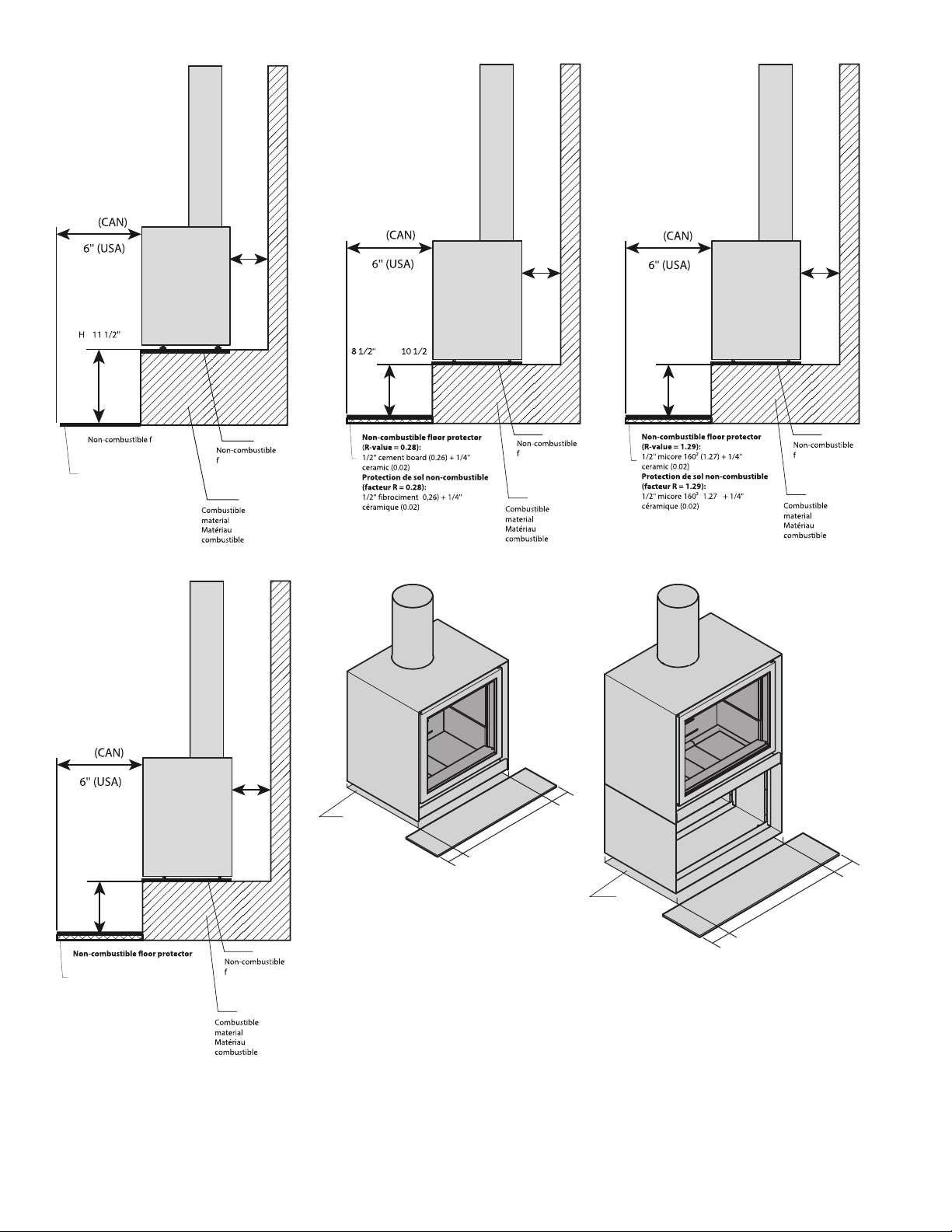
2.2 Dimensions & clearances 2.2 Dimensions et dégagements
The clearances are indicated for all types of
combustible materials (e.g.: wood, gypusm, etc.)
+Front clearance: 48”
+Rear clearance: 7”
+Side clearance: 12”
+Back corners clearance: 2’’
+Above clearance: 24-1/2”
A flameproof protective material must be laid on the
ground in front of the fireplace over a length of 18” for
Canada or 16’’ for the U.S. in front of the glass, and 6” on
each side of the glass.
Clearance from the bottom of the glass to the floor:
>see next page
CLEARANCES MAY ONLY BE REDUCED BY MEANS
APPROVED BY THE REGULATORY AUTHORITY.
We recommend to store solid fuel (wood logs) in a clean
and dry environment. Caution: do not place such fuel
within space heater installation clearanes or within the
space required for charging and ash removal.
Attemps to achieve heat output rates that exceed heater
design specifications can result in permanent damage to
the heater.
Les dégagements indiqués sont pour tout matériaux
combustible (ex.: Bois, Gypse, etc.).
+Dégagement avant : 48”
+Dégagement arrière : 7”
+Dégagement des côtés : 12”
+Dégagement coins arrières : 2’’
+Dégagement au dessus : 24-1/2”
Un matériau de protection incombustible doit être placé
au sol à l’avant de l’appareil sur une longueur de 18” au
Canada ou 16’’ aux USA devant la vitre, et 6” de chaque
côté de la vitre.
Dégagement entre le sol et le bas de la vitre :
>voir page suivante
LES DÉGAGEMENTS PRESCRITS NE PEUVENT ÊTRES
RÉDUITS QUE PAR DES MOYENS APPROUVÉS PAR
UNE AUTORITÉ DE RÉGULATION.
Nous vous recommandons de ranger le combustible
solide (bois de corde) dans un environnement propre et
sec. Attention : Ne placez pas ce genre de combustible
dans l’espace de dégagement d’instalation du poêle
d’ambianceou dans l’espace de chargement ou de
décendrage.
Tenter d’atteindre des niveaux de puissance supérieurs
à ceux prescrits pour cet insert peut endommager
définitivement celui-ci.
9
NOTE:
Any other installation case must be approved by STÛV.
REMARQUE :
Tout autre cas d’installation doit être approuvé par STÛV.
A value:
16/58: 23”
16/68: 27”
16/78: 31”
Valeur A:
16/58: 23”
16/68: 27”
16/78: 31”
18"
7"
H
loor
protector
Protection de sol non-
combustible
>
1
loor protector
Protection de sol
non-combustible
(
18"
7"
” < H < ”
H
1
loor protector
Protection de sol
non-combustible
( )
18"
7"
6 1/2” < H < 8 1/2”
H
1
loor protector
Protection de sol
non-combustible
18"
7"
4 1/2” < H < 6 1/2”
(R-value = 2.56):
1” micore 1602(2.54) +
1/4”ceramic (0.02)
Protection de sol non-combustible
(facteur R = 2.56):
1“ micore 1602(2.54) +
1/4”céramique (0.02)
H
1
loor protector
Protection de sol
non-combustible
A
6"
6"
A
6"
6"
Floor protector
Protection de sol
non-combustible
Non-combustible
Floor protector
Protection de sol
non-combustible
Non-combustible
10
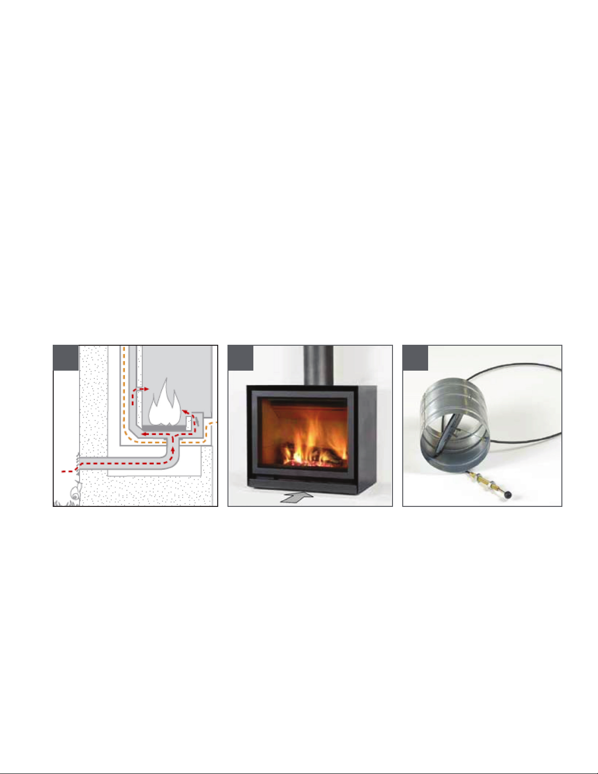
2.3 Combustion air inlet
The stove requires air for combustion (particularly when
installed in air-tight house).
The ideal solution
The Stûv 16 is designed to be directly connected to an
outside air inlet (independent of the air in the house). We
recommend this set-up. The connection is made below
the stove [diagrams 1].
If the stove is not connected directly to an outside air
inlet...(optional)
A sufficient air inlet (Ø 2-1/2”) should ideally be created
close to the stove.
This air inlet comes from a ventilated empty space, a
ventilated room (cellar) or from outside.
This set-up is mandatory in some countries or localities.
The air inlet adjustment can never be modified.
This wood heater has a manufacturer-set minimum
low burn rate that must not be altered. It is against
federal regulations to alter this setting or otherwise
operate this wood heater in a manner inconsistent
with operating instructions in this manual.
2.3 Arrivée d’air pour la combustion
Le poêle a besoin d’air pour la combustion
(particulièrement lorsqu’il est installé dans des maisons
très étanches).
La solution idéale
Le Stûv 16 est conçu pour être connecté directement
à une arrivée d’air extérieur (indépendant de l’air de la
maison). Nous recommandons cette disposition. La
connexion se fait par en dessous du poêle [schémas 1].
Si le poêle n’est pas directement raccordé à une
arrivée d’air extérieur… (facultatif)
Une arrivée d’air suffisante (ø 2-1/2”), doit idéalement
déboucher à proximité du poêle.
Cette arrivée d’air proviendra d’un vide ventilé, d’un local
ventilé (cave) ou de l’extérieur.
Cette disposition est obligatoire dans certaines localités.
L’ajustement d’entrée d’air ne doit en aucun cas être
modifié. Le niveau minimum d’air de combustion réglé
par le manufacturier ne peut pas être modifié. La loi
fédérale interdit toute alteration de l’insert ou son
usage non conforme au manuel d’instructions.
1 2 3

11
The duct that brings in outside air… (whether it is
connected to the free standing fireplace or not)
... will be protected on the outside by a grill where the free
passage section of which is at least equivalent to the
section of the air inlet. Please note that the infiltration of
water and the effect of the wind can damage the system.
... will ideally be fitted with a closure valve (for example,
the Stûv damper – see below) [photo 3] to prevent the
room from becoming cold when the stove is not in use.
... will be as short as possible and insulated to prevent
pressure loss and to keep the house from getting cold.
If you use our standard flexible Ø 2 ½’’ duct, we
recommend a maximum length of 78’’ and no more than
4 elbows (see table below).
If you exceed these guidelines, you must compensate
with a greater diameter and/or a smoother duct. Careful
not to crush the duct.
Length of flue Max. permitted ( 90°)
number of elbows
4’ 4 elbows
8’ 4 elbows
10’ 2 elbows
12’ 0 elbow
The air damper
[photo 3] prevents the house from becoming cold when
the stove is not in use. Has a 100% open or 100% closed
poition. Can never alter the burn rate.
This system is optional if you choose a connection directly
to the stove [diagrams 1 and 2].
However, it is still a good idea if the ducts are too long
to reach the stove or if it is being installed in an energy-
efficient house.
It should ideally be located as close as possible to the
outside wall.
Caution: length of the valve control cable = 48’’ and
damper diameter is Ø 4” (confirm Ø at time of order).
If it is not possible to bring in outside air near the
stove (most unfavourable case)...
...ensure there is sufficient replenishment of air in the
room when the stove is in use.
Caution:
Be careful with active air extraction systems (kitchen
hoods, air conditioning, mechanically-controlled
ventilation, and other stoves) in operation in the same
space or in an adjacent room. They also use a lot of air
and can cause a depression in the room and prevent
the stove from operating correctly (risk of backdraught).
They can affect the operation of the stove even if it is
connected to an outside air inlet.
Le conduit qui amène l’air extérieur... (qu’il soit
connecté au foyer ou pas)
... sera protégé à l’extérieur par une grille [schémas
2a-3a] dont la section de passage libre est au moins
équivalente à la section d’arrivée d’air. Attention aux
infiltrations d’eau et à l’influence des vents qui peuvent
annihiler le système.
... sera idéalement équipé d’un clapet de fermeture (par
exemple le clapet Stûv [photo 3]) pour éviter de refroidir
la pièce quand le poêle n’est pas en fonctionnement.
.... sera le plus court possible et isolé pour éviter des
pertes de charges et pour ne pas refroidir la maison.
Si vous utilisez notre conduit flexible standard ø 2 ½’’,
nous recommandons une longueur maximale 78’’ et pas
plus de 4 coudes (voir tableau qui suit).
Si vous dépassez ces prescriptions, il faudra compenser
par un diamètre plus important et/ou un tube plus lisse.
Veiller à ne pas écraser le conduit.
Longueur du conduit Nombre max.
de coudes (à 90°) autorisés
4’ 4 coudes
8’ 4 coudes
10’ 2 coudes
12’ 0 coudes
Le clapet de fermeture
[photo 3] empêche le refroidissement de la maison quand
le poêle n’est pas en fonctionnement. A une position
100% ouverte ou 100% fermée. Ne peut influencer la
combustion.
Ce dispositif est donc facultatif si vous optez pour un
raccordement direct sur le poêle [schémas 1 et 2].
Cependant, il reste intéressant si les longueurs de gaines
sont trop importantes jusqu’au poêle ou si l’installation
s’effectuedansune maisonàhaute efficacitéénergétique.
Il sera placé idéalement le plus près possible du mur
extérieur.
Attention: longueur du câble de commande du clapet
= 48’’ et le diamètre du clapet est de ø 4” (confirmer
le Ø au temps de la commande).
S’il n’est pas possible d’amener de l’air extérieur à
proximité du poêle (cas le plus défavorable)...
... s’assurer que le renouvellement d’air dans la pièce sera
toujours suffisant quand le poêle est en fonctionnement.
Note:
Attention aux systèmes d’extraction actifs d’air (hotte de
cuisine, air-conditionné, ventilation mécanique contrôlée,
autre poêles…) situés dans le même espace ou dans
une pièce contigüe. Ils consomment eux aussi beaucoup
d’air et pourraient créer une dépression dans le local
et perturber le bon fonctionnement du poêle (risque de
refoulement). Ils peuvent perturber le fonctionnement
du poêle même si celuici est raccordé à une arrivée d’air
extérieur.

12

13
2.5 Load bearing capacity of the
structure
Ensure that the floor is resistant enough to support the
stove; consult a specialist if in doubt.
2.6 The stove’s surroundings
The heat radiated from the glass door and the unit
may be significant. Whichever direction the stove is
facing, please adhere to the safety distances from
combustible materials [section 2.2] or ensure that the
materials exposed to radiate heat are resistant to high
temperatures.
Prevent “heat traps” in the cladding, recess and hood
If the stove is situated in a bell-shaped area (e.g.: a
former hearth), this space must be ventilated to prevent
“heat traps”.
2.5 Capacité portante de la structure
S’assurer que la résistance du plancher soit suffisante
pour supporter le foyer ; en cas de doute, consulter un
spécialiste.
2.6 Environnement du poêle
Le rayonnement de la vitre et des parois peut être
important. Quelque soit l’orientation du poêle, respectez
les distances de sécurité par rapport aux matériaux
combustibles [section 2.2], ou assurez-vous que les
matériaux exposés à ce rayonnement soient résistants à
de hautes températures.
Éviter les “pièges à chaleur” dans l’habillage, la niche
ou la hotte
Si le poêle se situe dans un environnement en forme de
cloche (ex : ancien âtre), cet espace doit être ventilé pour
éviter les “pièges à chaleur».
2.7 Tools required 2.7 Outils à prévoir
14
3. Installation
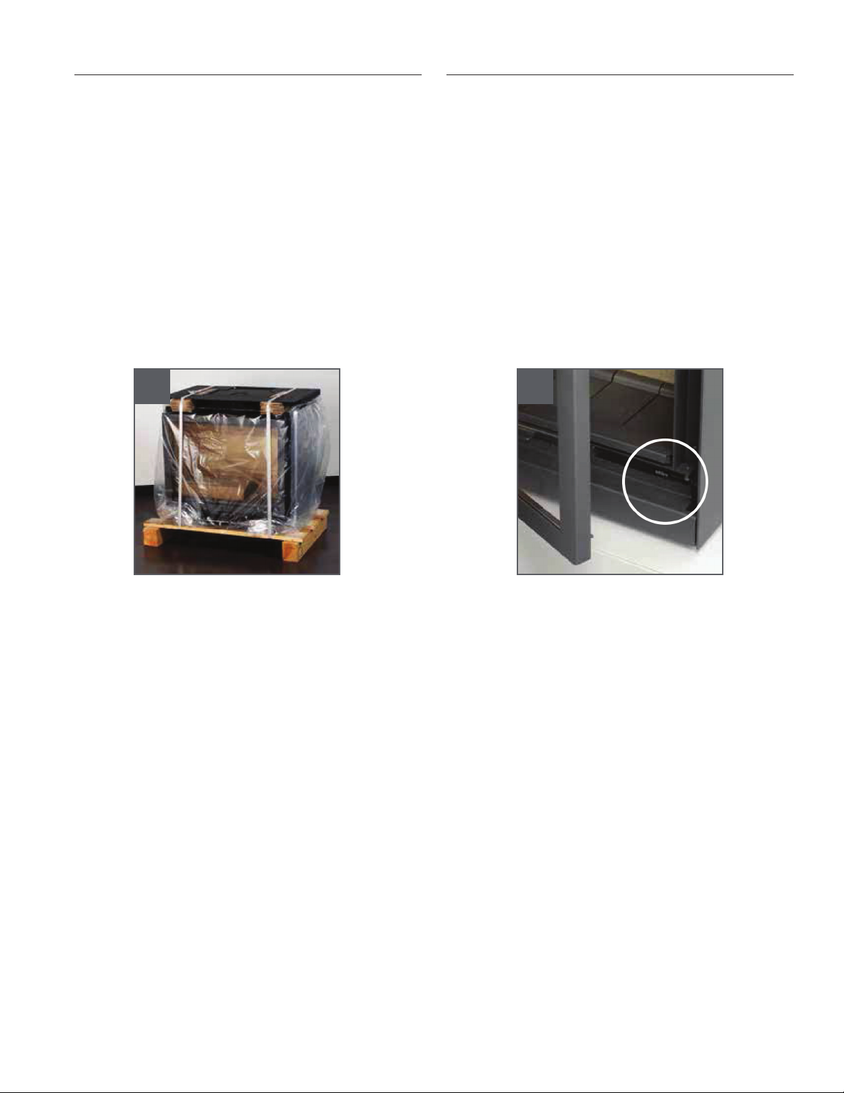
3.1 On taking delivery of the equipment
Please note !
Upon receipt of this fireplace, please ensure than
the glass door has not been damaged during delivery.
The guarantee only covers damage due to transport
if it is reported within 48 hours of delivery and it is
indicated on the delivery slip [picture 1].
Complaints
Always indicate the serial number visible on the
fireplace when making a complaint [picture 2].
3. Installation
1 2
3.1 À la réception du matériel
Attention !
Dès la réception de ce foyer, veuillez vérifier que la vitre
ne s’est pas brisée au cours de la livraison. En effet, la
garantie ne couvre les détériorations dues au transport
que si elles ont été signalées dans les 48 heures suivant
la réception et qu’elles ont été mentionnées sur le bon de
livraison [photo 1].
Réclamation
En cas de réclamation, communiquez toujours le n° de
série visible sur foyer [photo 2].

15
3.2 Unpacking
Please note !
The paint is not oven baked and is therefore
relatively fragile but will harden after being heated a
few times. Handle the system with care when installing.
Checking the order
Where accessories have been ordered (frame, support…),
they will be found around the hearth or its
packaging. Please check all accessories are supplied as
ordered.The installation instructions and the directions
for use are attached to the packaging.
Inside the combustion chamber, you will find...
a. Paint spray for touch-up
b. A flange
c. Flap
d. Tablet - N/A
e. Cold handgrip to handle the door and the
regulator lever
f. Handle for setting up the flue from inside the
fireplace
g. 4 x M10 headless screws for levelling
h. 4 M6 X 20 screws with hexagonal heads to attach
the plate
i. Installation instructions and directions for use
1
3.2 Déballage
Attention !
La peinture n'est pas cuite au four; elle est donc
relativement fragile mais elle durcira lors des premières
chauffes ; par conséquent, manipuler l'appareil avec
précaution lors de son installation.
Vérification de la commande
Si des accessoires ont été commandés (cadre,
support…), ils sont disposés autour du foyer ou de son
emballage. Contrôler la bonne réception de tous les
accessoires commandés.
Dans la chambre de combustion, vous trouverez...
a. Bombe de peinture pour retouches
b. Adaptateur pour cheminée
c. Abattant
d. Tablette - N/A
e. Poignée «main froide» pour manipuler la porte et
le registre
f. Barre en inox anti-ramoneur
g. 4 vis pour fixation avant du foyer au plateau de
prépose
h. 4 vis pour fixation arrière du foyer au plateau de
prépose
i. Instructions d'installation et mode d'emploi
16
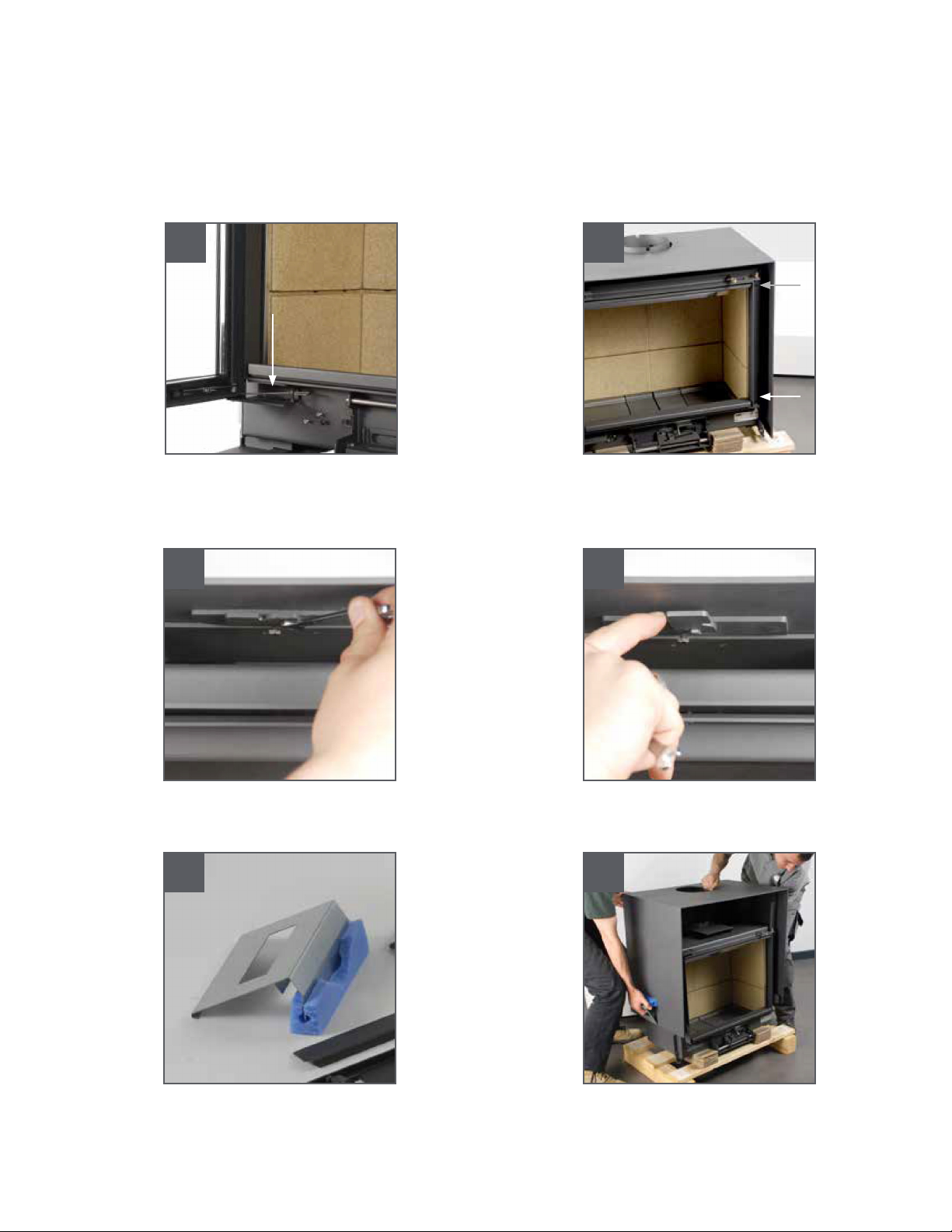
3.2 Unpacking
Before moving the stove
Dismantle the door: unfasten the resisting spring [photo
2], then remove it,
Lift off the cover
+remove the 4 screws on either side of the door
[photo 3],
+remove the upper part of the cover from the
freestanding fireplace. To do so, release the lock
by undoing the hexagonal-headed screw [photo
4] and turn the lock [photo 5],
+take off the cover using the grips provided
[photos 6 and 7].
2
4 5
6 7
3
3.2 Déballage (suite)
Avant de déplacer le foyer
Démonter la porte : décrocher le ressort de fermeture
[photo 4], puis soulever.
Démonter le capot :
+enlever les 4 vis de part et d'autre
[photo 3],
+désolidariser la partie supérieure du capot et le
foyer; pour ce faire, libérer le verrou en débloquant
la vis à tête hexagonale [photo 4] et faire pivoter le
verrou [photo 5],
+retirer le capot à l'aide des poignées fournies
[photos 6 et 7].
17
3.3 The support plate
The base plate [photo 1] is a key element in the system:
the outside air inlet duct is connected to it and the fan
and its accessories are attached to it.
It supports the freestanding fireplace itself.
It remains fixed.
It is positioned
+on the ground
+or on a brickwork base
+or on the adjustable support
+or on the ventilation chamber.
+or on a Stûv base,
+or on the “16-cube base” sub-unit to form a
Stûv 16-H.
In the two latter cases, see the instructions which
come with these accessories.
Whatever solution is chosen, the position of the
plate determines the position of the stove.
It is thus essential to align it accurately with the
smoke flue. A small hole cut in the sheet metal [photo 2]
indicates the verticality of the smoke outlet.
Please bear in mind that the front edge of the plate
will stand 5/16” back from flap [photo 3].
Prepare the base plate according to the
configuration chosen. See page 7.
3.4 Mounting the plate on the base to
form an Stûv 16 H
Consult the instrctions suppled with the accessory.
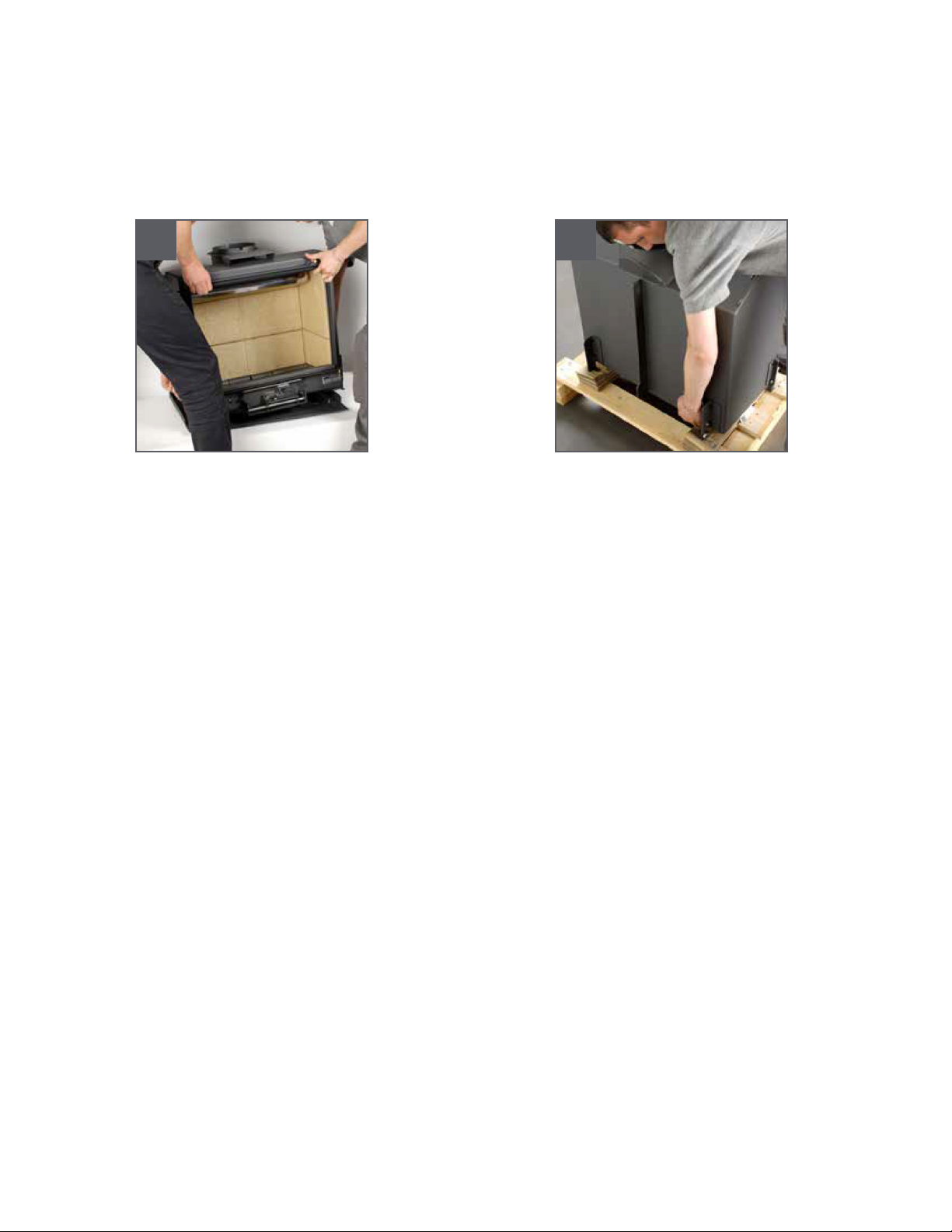
Moving the stove
+using a pallet truck: leave it on its pallet,
+using a hand truck: insert some cardboard to
protect the back of the stove, turn the stove onto
its back, leave the pallet in its position,
+by hand: take hold of the stove at the front [photo
8] and at the back [photo 9].
8 9
Déplacement du foyer
+avec un transpalette : le laisser sur sa palette,
+avec un diable : intercaler un carton pour
protéger le dos du foyer, basculer le foyer sur
son dos, laisser la palette sur place,
+à la main: saisir le foyer à l'avant [photo 8]
et à l'arrière [photo 9].
3.3 Le plateau de prépose
Le plateau de prépose est un élément essentiel du
système: on y raccorde la gaine d'arrivée d'air extérieur
et on y suspend le ventilateur avec ses accessoires.
Il supportera le foyer proprement dit.
Il reste fixe.
Il sera posé
+sur le sol,
+ou sur un socle maçonné,
+ou sur le support réglable,
+ou sur le caisson de ventilation
+ou sur un socle Stûv
+ou sur le sous-ensemble "base 16-cube" pour former
un Stûv 16 H.
Dans ces deux derniers cas, consulter aussi les instructions
qui accompagnent ces accessoires.
Quelle que soit la solution choisie, la position du plateau
conditionnera la position du foyer.
Il s’agit donc de le positionner correctement par rapport au
conduit de fumées. Un petit trou découpé dans la tôle
[photo 2] indique l’aplomb de la sortie de fumées.
Tenir compte du fait que le bord avant du plateau se
trouvera 8mm en retrait par rapport à l’abattant [photo 3].
Préparer le plateau de prépose en fonction de la
configuration que vous avez choisie. Voir page 7.
3.4 Montage du plateau sur la base pour
former un Stûv 16 H
Consulter les instructions accompagnant cet accessoire.
18
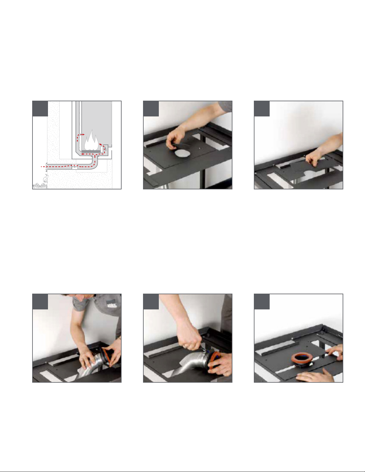
3.5 Combustion air connection
Air drawn from outside
If the stove is positioned on a Stûv base with a drawer
or on a Stûv 16 H base, please consult the instructions
which come with these accessories.
The combustion air is drawn from outside by means of a
duct [diagram 1] connected to the support plate.
Remove the plug [photo 2] and the cover at the front
[photo 3].
Fit the duct over the sleeve [photo 4] and secure it with a
clamp collar [photo 5] with the collar attachment turned
towards the back of the stove.
Insert the 2 M4 screws with hexagonal heads into the
cover at the front, put the sleeve between the 2 screws
[photo 6] and then fasten it all.
Ensure the plate is level and attach it to the base [photo
7].
1
4
2
5
3
6
3.5 L'air pour la combustion
L'air pour la combustion est prélevé à l'extérieur
Si le foyer est posé sur un socle à tiroir Stûv ou sur sur
base Stûv 16 H, consultez aussi les instructions qui
accompagnent ces accessoires.
L'air pour la combustion est prélevé à l'extérieur par une
gaine [schéma1], raccordée au plateau de prépose.
Enlever le bouchon [photo 2] et la trappe avant [photo 3].
Enfiler la gaine sur le manchon [photo 4] et la fixer par un
collier [photo 5], l'attache du collier tournée vers l'arrière
du foyer.
Engager les 2 vis M4 à tête hexagonale dans la trappe
avant et insérer le manchon entre le 2 vis [photo 6] et
refixer le tout.
Mettre le plateau à niveau et le fixer au socle [photo 7].

19
3.6 Positioning of the wood heater
Place the stove onto the plate.
The stove’s lug [photo 1-a] must be lowered onto the
hole [b] cut in the plate.
Fasten the stove to the plate using screws and nuts
[photos 2, 3 and 4].
Combustion air is drawn from the room where the
stove is installed
Make sure there will be adequate air renewal once the
stove is operating.
Remove all of the covers of the support plate [photo 8].
1
b
a
2 3
7 8
3.6 Placement du foyer
Déposer le foyer sur le plateau. L'ergot [photo 1-a] du
foyer doit tomber dans la découpe [b] du plateau.
Fixer le foyer sur le plateau par vis et écroux [photos 2, 3
et 4].
L'air pour la combustion provient de la pièce où est
installé le foyer
Vérifier que le renouvellement d’air sera toujours suffisant
quand le foyer sera en fonctionnement.
Enlever toutes les trappes du plateau de prépose [photo 8].

20
Put on the cover [photo 5]. The hole cut in the cover
should be centred in relation to the stove’s smoke outlet.
Attach the cover using the 4 screws at the front [photo 6],
starting with the lower screws.
The upper part of the cover has to be fixed to the stove
using a bolt provided for this purpose [photos 7 and 8].
Undo the bolt’s hexagonal screw [photo 7]
Swivel it 3/4 of a turn [photo 8] and retighten.
4
7
5
8
6
Déposer le capot [photo 5]. Centrer la découpe dans
le capot par rapport à la sortie de fumée du foyer.
Fixer le capot par les 4 vis à l'avant [photo 6] en
commençant par les vis inférieures.
La partie supérieure du capot doit être solidarisée avec
le foyer : un verrou est prévu à cet effet [photos 7 et 8].
Débloquer la vis hexagonale du verrou [photo 7]
Le faire pivoter de 3/4 de tour [photo 8] et le re-bloquer.
Other manuals for 16-cube Series
1
Table of contents
Other Stuv Wood Stove manuals


Popular Wood Stove manuals by other brands


ADURO
ADURO 22 Series manual

Dimplex
Dimplex MCFSTV1 manual

HearthStone
HearthStone 8040 04-28-04 owner's manual

Quadra-Fire
Quadra-Fire 51I-ACC-BK installation manual

Palazzetti
Palazzetti Ecomonoblocco 45 Series Instructions for use and maintenance

Lennox
Lennox Grandview GV 230 Installation and operation manual

Nibe
Nibe Contura C856W Style manual

Quadra-Fire
Quadra-Fire 57ST-ACC owner's manual

Blaze King
Blaze King CHINOOK CK30.1 Operation & installation manual

Waterford
Waterford Trinity Mk II Installation & operating instructions

Blaze King
Blaze King CHINOOK CK30.2 Operation & installation manual

Burley
Burley 9507 Installation instructions & user manual