d & b audiotechnik Z5385 Quick start guide
VZ5385
Rigging manual 1.4 en

S
y
m
b
o
l
s
o
n
t
h
e
p
r
o
d
u
c
t
P
l
e
a
s
e
r
e
f
e
r
t
o
t
h
e
i
n
f
o
r
m
a
t
i
o
n
i
n
t
h
e
m
a
n
u
a
l
.
W
A
R
N
I
N
G
!
D
a
n
g
e
r
o
u
s
v
o
l
t
a
g
e
!
General information
Z5385 Rigging manual
Version: 1.4 en, 07/2016, D2703.EN .01
Copyright © 2016 by d&b audiotechnik GmbH; all rights
reserved.
Keep this manual with the product or in a safe place
so that it is available for future reference.
When reselling this product, hand over this manual to the new
owner.
If you supply d&b products, please draw the attention of your
customers to this manual. Enclose the relevant manuals with the
systems. If you require additional manuals for this purpose, you
can order them from d&b.
d&b audiotechnik GmbH
Eugen-Adolff-Strasse 134, D-71522 Backnang, Germany
T +49-7191-9669-0, F +49-7191-95 00 00
[email protected], www.dbaudio.com

1. Z5385 V Flying adapter................................................ 4
1.1. Safety....................................................................................... 4
1.1.1. Intended use......................................................................... 4
1.1.2. General safety..................................................................... 4
1.1.3. Load safety information....................................................... 4
1.2. Scope of supply...................................................................... 4
2. Assembly............................................................................. 5
2.1. Suspension options................................................................. 5
2.2. Preparing the setup................................................................. 6
2.3. Order of assembly.................................................................. 6
2.4. Hoisting and securing the array (secondary safety)............. 9
3. Care and maintenance................................................ 10
3.1. Transport / Storing............................................................... 10
3.2. Visual and functional inspection.......................................... 10
4. Declarations..................................................................... 11
4.1. Manufacturer's declaration.................................................. 11
4.2. Disposal................................................................................. 11
Contents
d&b Z5385 Rigging manual 1.4 en 3

1.1. Safety
1.1.1. Intended use
The Z5385 V Flying adapter must only be used in conjunction with
the d&b V-Series V8 and V12 loudspeakers as described in this
manual.
1.1.2. General safety
Installation and setup should only be carried out by qualified and
authorized personnel observing the valid national Rules for the
Prevention of Accidents (RPA).
It is the responsibility of the person installing the assembly to ensure
that the suspension/fixing points are suitable for the intended use.
Always carry out a visual and functional inspection of the items
before use. In case there is any doubt as to the proper functioning
and safety of the items, these must be withdrawn from use
immediately.
Please also refer to Þ Chapter 3. "Care and maintenance"
on page 10.
1.1.3. Load safety information
NOTICE!
The Z5385 V Flying adapter is designed to suspend a total of 4 x
V8 or V12 cabinets which corresponds to a total system weight of
136 kg (300 lb) – SWL.
1.2. Scope of supply
Please verify the shipment for completeness and proper condition
of the items.
Qty. d&b Code Description
1Z5385 d&b V Flying adapter [1]
Including:
1 E6507 1t shackle [2]
1 D2703.EN .01 Z5385 Rigging manual
Weight 4.2 kg / 9.3 lb
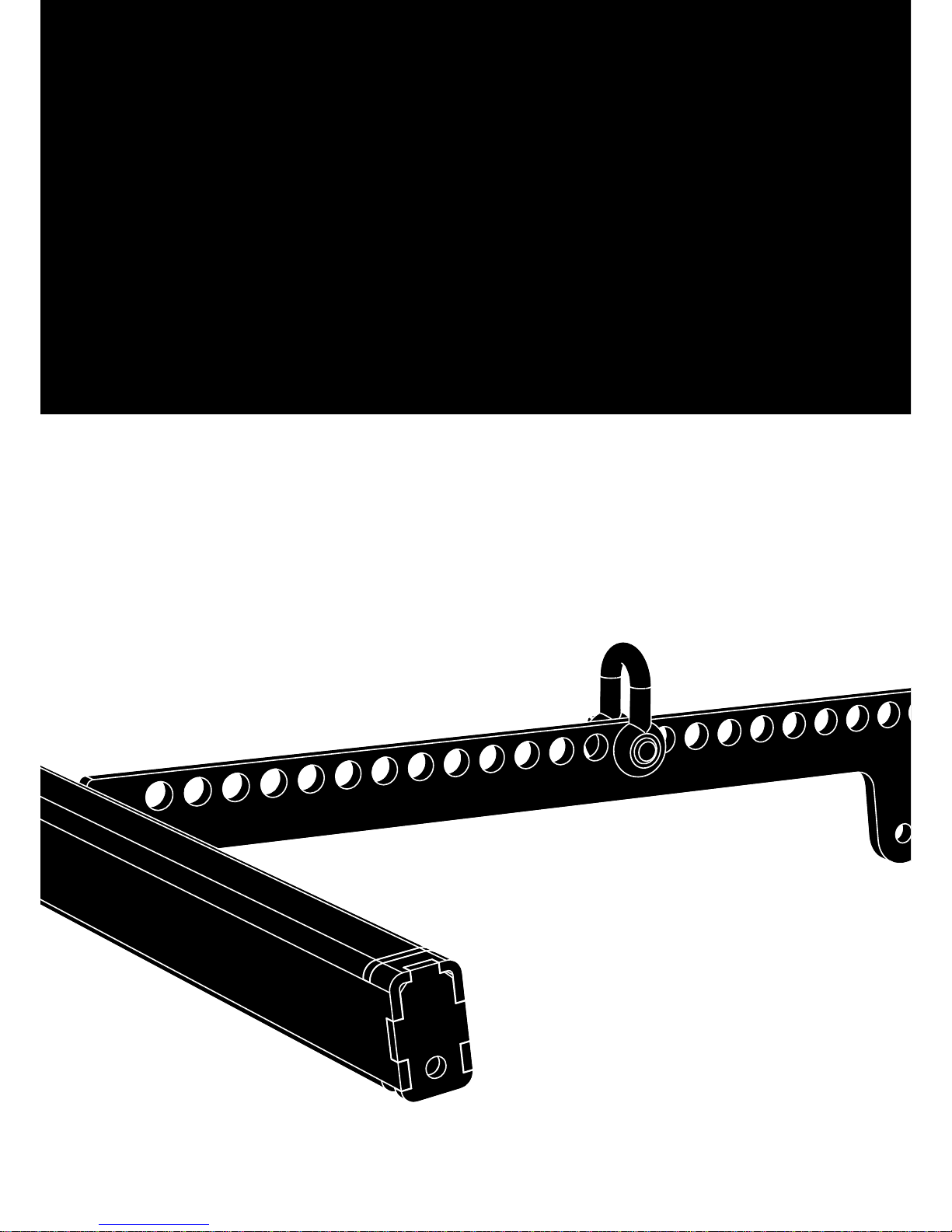
Z5385 V Flying adapter dimensions in mm [inch]
1. Z5385 V Flying adapter
d&b Z5385 Rigging manual 1.4 en4

2.1. Suspension options
The center bar of the adapter is equipped with a total of 27 holes
to allow the suspension of the array and the setting of different
vertical angles.
The holes are numbered with an increment of five.
Single or dual pick point operation
The array can be suspended using one or two E6507 1t shackle(s)
and appropriate lifting devices or steel wire ropes.
With "Dual pick point operation", the vertical aiming of the entire
array is set by trimming the respective lifting devices.
With "Single pickpoint operation", the overall vertical aiming of the
entire array is defined by using a particular hole of the hole index
of the center bar.
The corresponding hole position is calculated using the d&b
ArrayCalc simulation software. For this purpose, ArrayCalc can be
downloaded at www.dbaudio.com.
Note: Please note that you have to check the «Rigging plot»
page within ArrayCalc, as the «Sources» page only indicates
hole numbers for the Z5380 V Flying frame, but not for the
Z5385 V Flying adapter.
The use of ArrayCalc is described in "TI 385 d&b Line array
design, ArrayCalc" which is included in the ArrayCalc
software. The TI can also be downloaded at
www.dbaudio.com.
In ArrayCalc, the closest pickpoint hole and the exact distance in
cm/inch are displayed in the «Main» array section Þ
«Pickpoints and load» (last entry) on the «Rigging plot» page,
provided the corresponding array is selected on this page.
Z5147 Rota clamp option
Alternatively, the array can be suspended and horizontally aligned
from a single pickpoint using the d&b Z5147 Rota clamp. The
clamp allows the load to be attached to overhead bars or truss
with a tube diameter of up to 51 mm (2”).
Attachment
Choose the appropriate hole position in the center bar according
to the ArrayCalc calculation and attach the Rota clamp
correspondingly.
Note: Please observe the relevant mounting instructions
which are enclosed with the Rota clamp.
2. Assembly
d&b Z5385 Rigging manual 1.4 en 5
2.2. Preparing the setup
General
Check the acoustical and mechanical setup using ArrayCalc and
prepare enough printouts for each array.
The plan enables the riggers to set up the suspension points, the
securing points and the chain hoists.
When on site first:
– Clear the working areas and ensure there is enough space to
set up and lift the array.
– Check that the hoists are exactly in the specified position.
– Ensure the chains are not twisted.
– Prepare the cables and link cables according to the number of
amplifier channels and cabinets used.
Inspections before setup
Before setup carry out a visual inspection of all system components
for faults. This also includes the loudspeakers and in particular the
rigging parts of the cabinets (Front and Splay/Rear links).
Damaged components must be withdrawn from use immediately.
Please follow the instructions given in Þ Chapter 3. "Care and
maintenance" on page 10.
2.3. Order of assembly
Due to the compact size of the V-Series TOP cabinets and the
maximum number of four cabinets that can be flown, the assembly
may be carried out either suspended or on the ground. The
following description refers to the suspended assembly.
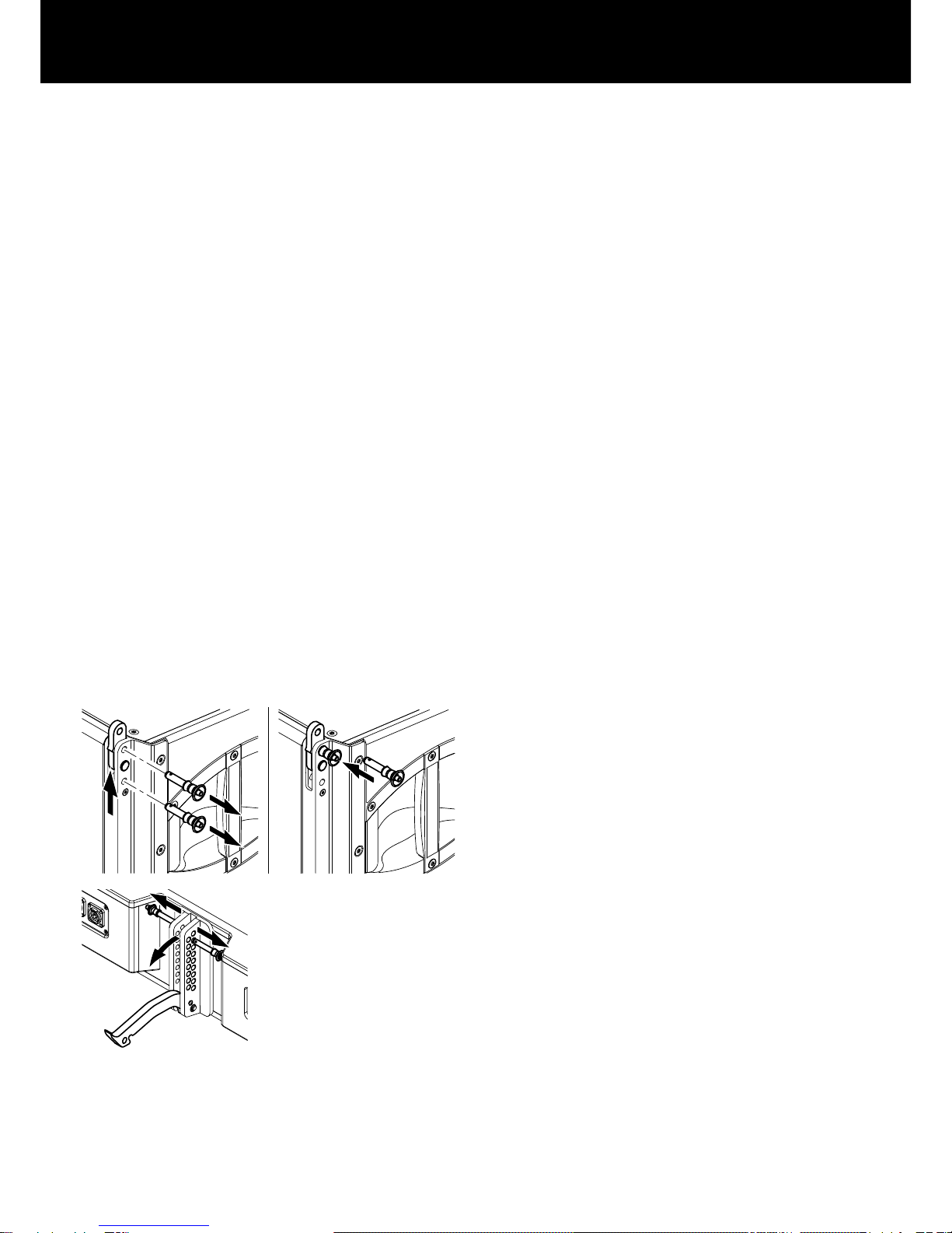
1. Prepare the first cabinet
1. At the front release both Locking pins and slide out the Front
link.
2. Insert and lock one Locking pin to fix the link in place.
2. On the rear release both Locking pins and fold out the Splay
link.
d&b Z5385 Rigging manual 1.4 en6
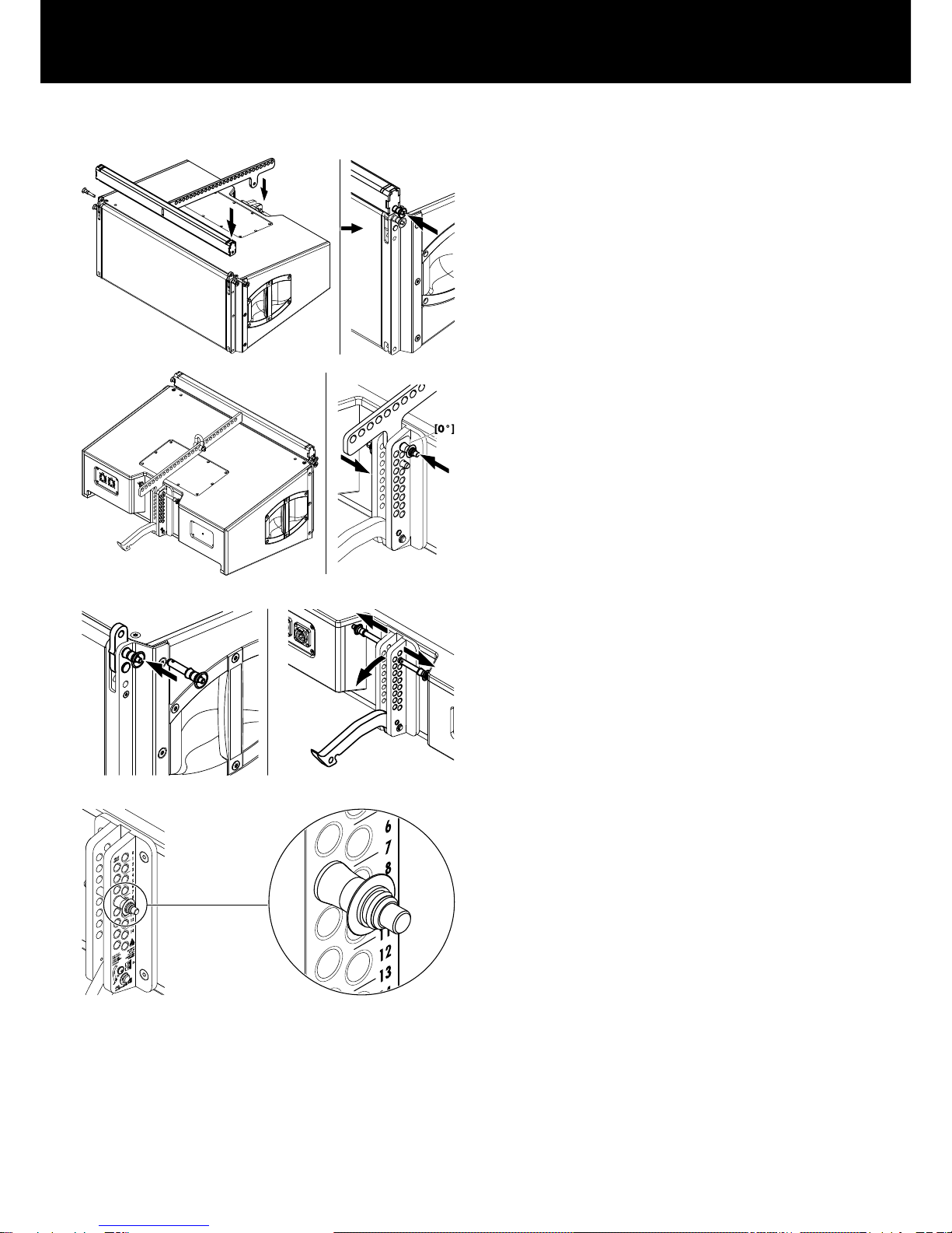
2. Attach the Flying adapter
1. Attach the Flying adapter on top of the cabinet until the Front
links of the cabinet fit into the slots at the front of the adapter.
2. Insert and lock the second Locking pins of the cabinet's Front
links on both sides.
3. On the rear align the Flying adapter with the [0°] hole of the
rear rigging strand.
4. Insert and lock one Locking pin in the [0°] hole.
Note: The second Locking pin is not needed and can be
stored in one of the remaining holes.
3. Prepare the next cabinet
1. Prepare the Front and Splay links of the next cabinet.
4. Preset the splay angle
The splay angles between adjacent cabinets are set at the central
rear rigging strands of the cabinets and can be set in the range
from 0° to 14° in 1° steps.
ÞPreselect the splay angle according to your ArrayCalc
simulation and insert and lock one Locking pin in the
appropriate hole.
d&b Z5385 Rigging manual 1.4 en 7

5. Attach the next cabinet
1. Suspend the assembly according to the desired suspension
option.
2. Lift the assembly to a suitable working height.
3. Attach the prepared cabinet to the corresponding slots on the
front of the upper cabinet.
4. Insert and lock the second Locking pins of the cabinet's Front
links on both sides.
5. Raise the bottom cabinet until the hook of the Splay link of the
upper cabinet has hooked into the preset Locking pin.
6. Release the cabinet and insert the second Locking pin (Safety
pin) to secure the Splay link.
To add further cabinets, proceed in the same manner until the
assembly is completed.
6. Splay link of the last cabinet
The Splay link of the last cabinet can be kept in its park position.
Note: In this case, the lowest cabinet can be set to the
following splay angles: 3°, 5° and 7° to 14°.
7. Rig the cabling
Connect the flying cables and link cables according to the number
of amplifier channels and cabinets used.
8. Check the assembly
Before hoisting the array to its operating position recheck the
actual status of the entire assembly.
– Check the attachment of the shackles or Rota clamp to the
Flying adapter.
– Check the attachment of the Flying adapter to the first cabinet
and ensure all Locking pins are properly inserted and locked.
– Check all Front links on both sides of the cabinets and ensure
all Locking pins are properly inserted and locked.
– Check the splay angle settings and the Splay links on the rear
of the cabinets and ensure all Locking pins are properly
inserted and locked.
– In "Single pick point operation" check the desired total vertical
aiming of the entire array using an inclinometer.
d&b Z5385 Rigging manual 1.4 en8

2.4. Hoisting and securing the array (secondary
safety)
When all the mechanical adjustments, system checks and safety
checks have been made, the array can be hoisted up to its
operating position.
When hoisting the array, ensure that the loudspeaker cables do
not get caught anywhere. The cables can be strapped together
with the motor cable to form a loom while the system is hoisted.
The chain hoist motors must raise the system slowly and evenly so
that it does not swing or move from side to side during hoisting.
When the array is in its final operating position the secondary
safety must be applied.
d&b Z5385 Rigging manual 1.4 en 9
3.1. Transport / Storing
During transport ensure the rigging components are not stressed or
damaged by mechanical forces. Use suitable transport cases.
Due to their surface treatment the rigging components are
temporarily protected against moisture. However, ensure the
components are in a dry state while stored or during transport and
use.
3.2. Visual and functional inspection
WARNING!
Potential risk of personal injury and/or
damage to material
To eliminate the potential risk of accident due to malfunctioning of
a component, regularly inspect all system components.
Cabinet enclosure
– Visual inspection of all fitting plates for obvious damage (e.g.
cracks or corrosion).
– Visual inspection of the rear rigging strand for obvious
damage (e.g. cracks, deformation or corrosion) including all
drilled holes of the component.
– Inspection of all fitting plates including front grills to ensure
they are securely attached.
– Regularly lubricate the sockets using WD-40® or a similar
product.
Front and Splay links
Visual inspection regarding deformation and damage (e.g. cracks
and corrosion) including all drilled holes of the component.
Locking pins
– Visual inspection for deformation, cracks and corrosion of the
component.
– Inspection for missing ball bearings and damage.
– Functional inspection of the release mechanism to ensure it
operates properly.
– Regularly lubricate the Locking pins using WD-40® or a similar
product.
Z5385 V Flying adapter
Visual inspection regarding deformation and damage (e.g. cracks
and corrosion) including all drilled holes of the component.
3. Care and maintenance
d&b Z5385 Rigging manual 1.4 en10

4.1. Manufacturer's declaration
This declaration covers:
– d&b Z5385 V Flying adapter.
National standards and technical specifications
applied:
DIN 18 800, DIN 1055, DGUV Vorschrift 17.
Backnang, 2012-02-27
Frank Bothe,
Head of R&D
d&b audiotechnik GmbH
4.2. Disposal
When out of use the rigging components must be disposed of in
accordance with the national environmental regulations.
Ensure that damaged rigging components are disposed of in a
way that they cannot be used again.
4. Declarations
d&b Z5385 Rigging manual 1.4 en 11

D2703.EN .01, 07/2016 © d&b audiotechnik GmbH
www.dbaudio.com
Table of contents
Other d & b audiotechnik Adapter manuals

d & b audiotechnik
d & b audiotechnik Z5160 User manual

d & b audiotechnik
d & b audiotechnik Z5356 E4 User manual

d & b audiotechnik
d & b audiotechnik Z5354 User manual

d & b audiotechnik
d & b audiotechnik Z5357 User manual

d & b audiotechnik
d & b audiotechnik Z5396 Quick start guide

d & b audiotechnik
d & b audiotechnik Z5024 User manual


