D'Orly RH Series User manual

MANUAL
DA64FN

Angle Finish Nailer DA64R Http://www.aeroprotools.com 1
Operating Instruction
and safety manual
34°Angle Finish Nailer Model: DA64R
1.Air Inlet Coupler 2. No-mar pad
3. Exhaust cap 4. Air Supply
5. Nails 6.Pusher
7.Magazine 8.Trigger
9.Depth adjustment knob 10.Safety yoke
11.Jam release
IMPORTANT:
Please read and fully understand this manual for information relating to protecting your
safety and preventing equipment problems.
And retain this manual for future reference.
DESCRIPTION
Operating Instruction

Angle Finish Nailer DA64R Http://www.aeroprotools.com 2
GENERAL SAFETY RULES
For multiple hazards, read and understand the safety instructions before installing, operating, repairing, maintaining, changing
accessories on, or working near the air tool. Failure to do so can result in serious bodily injury.
Only qualified and trained operators should install, adjust or use the air tool.
Do not modify this air tool. Modifications can reduce the effectiveness of safety measures and increase the risks to the operator.
Do not discard the safety instructions; give them to the operator. Do not use the air tool if it has been damaged.
Tools shall be inspected periodically to verify that the ratings and markings required by this part of EN 792-13 are legibly marked on
the tool. The employer/user shall contact the manufacturer to obtain replacement marking labels when necessary.
PROJECTILE HAZARDS
Be aware that the failure of the work piece, or accessories, or even of the fastener driving tool itself, can generate high-velocity
projectiles.
Always wear impact-resistant eye protection during the operation of the air tool. The grade of protection required should be
assessed for each use.
Ensure that the work piece is securely fixed.
ENTANGLEMENT HAZARDS
Choking, scalping and/or lacerations can occur if loose clothing, personal jewellery, neck wear, hair or gloves are not kept away
from the tool and accessories.
OPERATING HAZARDS
Operators and maintenance personnel shall be physically able to handle the bulk, weight and power of the tool.
Hold the tool correctly; be ready to counteract normal or sudden movements and have both hands available.
Maintain a balanced body position and secure footing.
Release the start-and-stop device in the case of an interruption of the compressed air supply.
Use only lubricants recommended by the manufacturer.
Personal protective safety glasses shall be used; suitable gloves and protective clothing are recommended.
REPETITIVE MOTIONS HAZARDS
When using an air tool to perform work-related activities, the operator can experience discomfort in the hands, arms, shoulders,
neck or other parts of the body.
While using an air tool, the operator should adopt a comfortable posture while maintaining a secure footing and avoiding awkward
or off-balanced postures. The operator should change posture during extended tasks, which can help avoid discomfort and fatigue.
If the operator experiences symptoms, such as persistent or recurring discomfort, pain, throbbing, aching, tingling, numbness,
burning sensations or stiffness, these warning signs should not be ignored. The operator should tell the employer and consult a
qualified health professional.
ACCESSORY HAZARDS
Disconnect the air tool from the compressed air line before fitting or changing the fasteners or accessory.
Use only sizes and types of accessories and consumables that are recommended by the air tool manufacturer; do not use other
types or sizes of accessories and consumables.
WORKPLACE HAZARDS
Slips, trips and falls are major causes of workplace injury. Be aware of slippery surfaces caused by the use of the tool and also of
trip hazards caused by the air line.
Proceed with care in unfamiliar surroundings. There can be hidden hazards, such as electricity or other utility lines.
The air tool is not intended for use in potentially explosive atmospheres and is not insulated against coming into contact with
electric power.
Ensure that there are no electrical cables, gas pipes, etc., that can cause a hazard if damaged by use of the tool.
NOISE EMISSION
The characteristic noise values for the fastener driving tool have been determined in accordance with EN12549:1999 and EN ISO4871
"Acoustics-Noise test code for fastener driving tools-Engineering method”(see specifications).These values are tool-related characteristic
values and do not represent the noise development at the point of use. Noise development at the point of use will for example depend
on the working environment, the work piece, the work piece support, the number of driving operations, etc. Depending in the
conditions at the workplace and the form of the workplace, individual noise attenuation measures may need to be carried out, such as
placing work pieces on sound-damping supports, preventing work piece vibration by means of clamping or covering, adjusting to the
minimum air pressure required for the operation
involved, etc.
In special cases it is necessary to wear hearing protection equipment.
INFORMATION ON MECHANICAL IMPACT (VIBRATION)

Angle Finish Nailer DA64R Http://www.aeroprotools.com 3
The characteristic vibration values for the fastener driving tool have been determined in accordance with ISO 8662-11:1999 and EN
12096 ¨C Measurement of vibration in hand-held power tools - Part 11: Fastener driving tools(see specifications).
This value is a tool-related characteristic value and does not represent the influence to the hand-arm-system when using the tool. An
influence to the hand-arm-system when using the tool will for example depend on the gripping force, the contact pressure force, the
working direction, the adjustment of compressed air supply, the workplace and the work piece support.
ADDITIONAL SAFETY INSTRUCTIONS FOR PNEUMATIC POWER TOOLS
Air under pressure can cause severe injury.
Always shut off air supply, drain hose of air pressure and disconnect tool from air supply whenever not in use, before changing
accessories or where making repairs.
Never direct air at yourself or anyone else.
Whipping hoses can cause severe injury. Always check for damaged or loose hoses and fittings.
Cold air should be directed away from the hands.
Whenever universal twist couplings(claw couplings) are used, lock pins shall be installed and whip check safety cables shall be used
to safeguard against possible hose-to-tool and hose-to-hose connection failure.
Do not exceed the maximum air pressure stated on the tool.
Never carry an air tool by the hose.
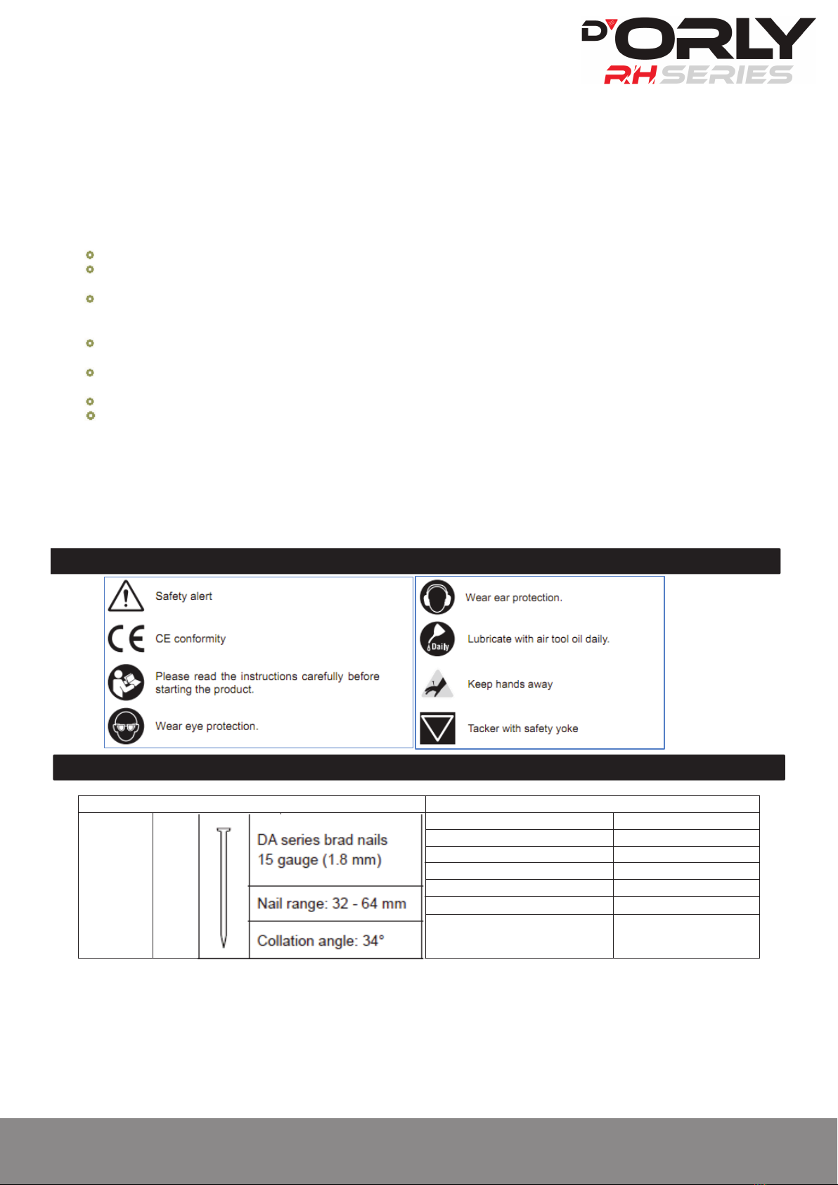
Only fasteners listed in the specifications may be used in the fastener driving tool. The fastener driving tool and the fasteners
specified in the specifications are to be considered as one unit safety system.
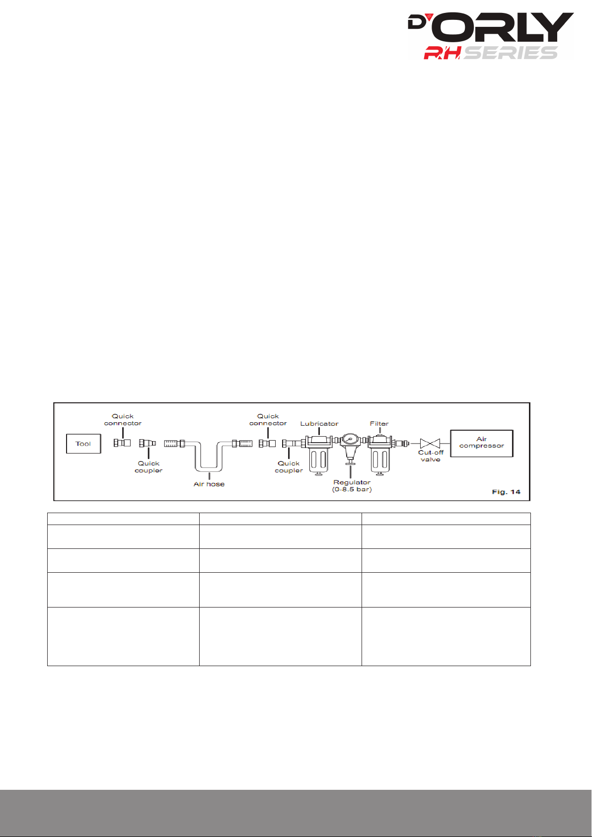
Quick action couplings shall be used for connection to the compressed air system and the non-sealable nipple must be fitted at the
tool in such a way that no compressed air remains in the tool after disconnection.
Oxygen or combustible gases shall not be used as an energy source for compressed air operated fastener driving tools.
Fastener driving tools shall only be connected to an air supply where the maximum allowable pressure of the tool cannot be
exceeded by more than 10%; in the case of higher pressure ,a pressure reducing valve which includes a downstream safety valve
shall be built into the compressed air supply.
Only the main energy and the lubricants listed in the operating instructions may be used for the maintenance of fastener driving
tools. Only spare parts specified by the manufacturer or his authorised representative shall be used.
Repairs shall be carried out only by the manufacturer's authorized agents or by other experts, having due regard to the
information given in the operating instructions.
Stands for mounting the fastener driving tools to a support, for example to a work table, shall be designed and constructed by the
stand manufacturer in such a way that the fastener driving tools can be safely fixed for the intended use, thus for example
avoiding damage, distortion and displacement.
Check prior to each operation that the safety and triggering mechanism is functioning properly and that all nuts and bolts are right.
Do not carry out any alterations to the fastener driving tool.
Do not disassemble or make inoperative any parts of the fastener driving tool such as the safety yoke.
Do not perform any ¡°emergency repairs¡± without proper tools and equipment.
The fastener driving tool should be serviced properly and at regular intervals in accordance with the manufacturer¡¯s instructions.
Avoid weakening or damaging the tool, for example by:
-punching or engraving;
-modification not authorized by the manufacturer;
-guiding against templates made of hard material such as steel;
-dropping or pushing across the floor;
-using the tool as a hammer;
-applying excessive force of any kind.
Never point any fastener driving tool at yourself or at any other person or animal.
Hold the fastener driving tool during the work operation in such a way that no injuries can be caused to the head or to the body in
the event of possible recoil consequent upon a disruption in the compressed air supply or hard areas within the workplace.
Never actuate the fastener driving tool into free space. This will avoid any hazard caused by free flying fasteners and excessive
strain of the tool.
The tool shall be disconnected from the compressed air system for the purpose of transportation, especially where ladders are
used or where an unusual physical posture is adopted whilst moving .
Carry the fastener driving tool at the workplace using only the handle, and never with the trigger actuated.
Take conditions at the workplace into account. Fasteners can penetrate thin work pieces or slip off corners and edges of
workplaces, and thus put people at risk.
For personal safety, use protective equipment such ad hearing and eye protection.
Fastener driving tools are operated by actuating the trigger using finger pressure.

Angle Finish Nailer DA64R Http://www.aeroprotools.com 4
In addition, fastener driving tool is fitted with a safety yoke which enables the driving operation to be carried out only after the safety
yoke of the tool is pressed against a work piece, These tools are marked with an inverted triangle ▽behind the serial number and are
not permitted for use without an effective safety yoke. A safety yoke is not required on fastener driving tools which accelerate the
heaviest usable fasteners to a free flight velocity below an admissible risk of injury. Those fastener driving tools are not marked with an
inverted triangle.
SAFETY INSTRUCTIONS FOR COMPRESSED AIR SYSTEM
Proper functioning of the fastener driving tool requires filtered, dry and lubricated compressed air in adequate quantities.
If the air pressure in the line system exceeds the maximum allowable pressure of the fastener driving tool, a pressure reducing
valve followed by a downstream safety valve shall additionally be fitted in the supply line to the tool.
The compressor plant shall be adequately dimensioned in terms of pressure output and performance(volumetric flow) for the
consumption which is to be expected. Line sections which are too small in relation to the length of the line(pipes and hoses), as
well as overloading the compressor, will result in pressure drops.
Permanently laid compressed air pipelines should have an internal diameter of at least 19 mm and a corresponding large diameter
where relatively long pipelines or multiple users are involved.
Compressed air pipelines should be laid so as to form a gradient (highest point in the direction to the compressor ). Easily
accessible water separators should be installed at the lowest points.
Junctions for users should be joined to the pipelines from above,
Connecting points for fastener driving tools should be fitted with a compressed air servicing unit (filter/water separator/oiler)
directly at the junction point.
RESIDUAL RISKS
Even if you are operating this product in accordance with all the safety requirements, potential risks of injury and damage remain. The
following dangers can arise in connection with the structure and design of this product:
1. Health defects resulting from vibration and noise emission if the product is being used over long periods of time or not adequately
managed and properly maintained.
2. Injuries and damage to property due to fasteners or the sudden impact of hidden objects during use.
3. Danger of injury and property damage caused by flying objects.
FASTENER
TOOL
Nail type
Magazine capacity
100pcs
Air inlet size
1/4”(6.35mm)
Air hose size
3/8”(9.52mm)
Max working pressure
120PSI(8.3bar)
Working pressure range
80-120PSI(5.5-8.3bar)
Exhaust
Rear adjustable(360
°
)
Tool weight(no nails)
2.09kg(4.6lb)
SYMBOLS
SPECIFICATIONS

Angle Finish Nailer DA64R Http://www.aeroprotools.com 5
PREPARING THE TOOL FOR USE (See figure1)
Under normal use conditions, the tool should be lubricated with air tool oil before connecting the tool to an air supply. daily with
minimal use, or twice a day with heavy use. Only a few drops of oil at a time is necessary. Too much oil will only collect inside the tool
and will be noticeable in the exhaust cycle. Before connecting the tool, check the air compressor gauge to be sure it is functioning within
the proper range
NO-MAR PAD (See figure 2)
The no-mar pad attached to the safety yoke of the tool helps prevent marring and denting when working with softer woods.
The pad can be removed by pulling it down and away from the safety yoke. To replace the pad, fit it into place over the safety yoke and
push up at the back to reseat.
ADJUSTING THE EXHAUST (see figure 3)
The adjustable exhaust on the end cap of the tool allows the operator to direct the exhaust according to operator preference. To adjust,
turn the exhaust cap in the desired direction.
CONNECTING THE TOOL TO AN AIR SUPPLY (see figure 4)
This tool is designed to operate on clean, dry compressed air at regulated pressures between 5.5 - 8.3 bar (80 –120psi). The correct air
pressure is the lowest pressure that will do the job.
NOTE: Air pressure that is higher than 8.3Bar (120psi)may damage the tool.
The tool and air hose must have a hose coupling that allows all pressure to be removed from the tool when the coupling is disconnected.
Connect the tool to the air supply with a 1/4 in. female quick connector. For maximum tool performance, a 3/8 in. supply line and fitting
are required.
LOADING THE TOOL WITH FASTENERS (see figure 5-6)
1. Connect the tool to the air supply.
2. With the safety yoke of the tool pointed away from you, feed a strip of fasteners into the magazine. Be sure the fasteners are pointed
downward and at the angle shown.
3. Slide the pusher all the way to the rear of the magazine.
4. Release the pusher and allow it to push the fasteners to the driving mechanism. The pusher will stop when it rests against the end of
the fastener strip.
NOTE: Do not allow the pusher to snap back into place.
DRIVING A FASTENER (see figure 7)
Avoid triggering the fastener driving tool if the magazine is empty.
Any defective or improperly functioning fastener driving tool must immediately be disconnected from the compressed air supply and
passed to a specialist for inspection.
In the event of longer breaks in work or at the end of the working shift, disconnect the tool from the compressed air supply and it is
recommended to empty the magazine.
The compressed air connectors of the fastener driving tool and the hoses should be protected against contamination, the ingress of
coarse dust chips, sand, etc, will result in leaks and damage to the fastener driving tool and the couplings.
Single sequential actuation mode
The tool employs single sequential actuation mode.
1. Connect the tool to the air supply. 2. Grip the tool firmly to maintain control. Position the safety yoke of the tool onto the work
surface.3. Push the tool against the work surface to depress the safety yoke.4. Squeeze the trigger to drive a fastener.5. Allow the tool
to recoil away from the work surface as the fastener is driven.
6. Always remove your finger from the trigger after the fastener has been driven.
NOTE: If there is only one nail left in the magazine, it may not be fully driven into the workpiece, may be bent or fall out.
SETTING THE AIR PRESSURE
Having checked that the fastener driving tool is functioning correctly, apply the tool to a work piece and actuate the trigger.
Check whether the fastener has been driven into the work piece in accordance with the requirements.
If the fastener is protruding, increase the air pressure in increments of 0.5 bar, checking the result after each new adjustment;
NOISE AND VIBRATION
INTENDED USE
Noise according to EN 12549:1999 and EN ISO 4871
The tool can be used for the purposes listed below:
A-weighted sound pressure level
LPA=91.1dB(A),KPA=2.5dB
Finish and trim(Interior and exterior),Door and
window architraves and moulding, Door jambs,
Skirting boards, Crown mouldings, Fascia boards,
Staircases, Hardwood flooring, Panelling and lining,
Shelving.
Sound power level
LWA=104.1dB(A),KWA=2.5dB
C-weighted sound pressure level
LPC=119.5dB(A),KPC=2.5dB
Vibration according to ISO 8662-11:1999
Vibration in the handle
W=2.14m/s
²
K=2m/s
²

Angle Finish Nailer DA64R Http://www.aeroprotools.com 6
If the fastener is driven into an excessive depth, reduce the air pressure in increments of 0.5 bar until the result is satisfactory.
It is preferred to adjust the depth adjustment knob to reach the good fastening effect.
Work with the lowest possible air pressure. This will give you three significant advantages:
1. Energy will be saved,
2. Less noise will be produced,
3. A reduction in fastener driving tool wear will be achieved.
The amount of air pressure required will depend on the size of the fastener and the workpiece material.
Begin testing the depth of drive by driving a test fastener into the same type of workpiece material used for the actual job.
Drive a test fastener with the air pressure set at 6.2 - 6.5 (90-95psi).Raise or lower the air pressure to find the lowest setting that will
perform the job with consistent results.
It may be possible to achieve the desired depth with air pressure adjustments alone. If finer adjustments are needed, use the drive
depth adjustment on the tool.
DRIVE DEPTH ADJUSTMENT(see figure 8)
The driving depth of the fastener may be adjusted. It is advisable to test the depth on a scrap workpiece to determine the required
depth for the application. To determine depth of drive, first adjust the air pressure and drive a test fastener. To achieve the desired
depth, use the drive depth adjustment on the tool.
1. Disconnect the tool from the air supply.
2. Turn the depth adjustment knob left or right to change the driving depth.
3. Reconnect the tool to the air supply.
4. Drive a test fastener after each adjustment until the desired depth is set.
REMOVING FASTENERS FROM THE TOOL(see figure 9)
1. Disconnect the tool from the air supply.
2. To remove a strip of fasteners from the tool, retract the pusher until it reaches the end of the magazine .Hold the pusher in place.
NOTE: Always keep fingers clear of fastener track of magazine to prevent injury from unintended release of the pusher.
3. Tilt the tool up so that the hose connector faces down. Press the pusher button and slowly release the pusher to the front of the
magazine. The strip of fasteners will slide back until it reaches the stopper.
4. Press the stopper and let the fasteners exit the rear of the magazine.
CLEARING A JAMMED FASTENER(see figure 10)
If a fastener becomes jammed in the tool, disconnect the air hose and keep the tool pointed away from you while clearing the jam.
1. Disconnect the tool from the air supply.
2. Remove fasteners from the tool.
3. Pull up on the latch and open the jam release.
4. Insert a flat blade screwdriver into the driving mechanism and push the driver mechanism back, freeing the fastener jam.
5. Remove the jammed fastener.
6. Close the jam release and latch.
7. Reconnect the tool to the air supply.
8. Reinstall fasteners.
GENERAL MAINTENANCE
Avoid using solvents when cleaning plastic parts. Most plastics are susceptible to damage from various types of commercial solvents and
may be damaged by their use.
Use clean cloths to remove dirt, dust, oil, grease, etc.
COLD WEATHER OPERATION
For cold weather operation, near and below freezing, the moisture in the air line may freeze and prevent tool operation. We
recommend the use of air tool lubricant or permanent antifreeze (ethylene glycol) as a cold weather lubricant.
NOTE: Some commercial air line drying liquids are harmful to”O” rings and seals. Do not use these low temperature air dryers without
checking compatibility.
AIR SUPPLY PRESSURE AND VOLUME
Air volume is as important as air pressure. The air volume supplied to the tool may be inadequate because of undersize fittings and
hoses, or from the effects of dirt and water in the system. Restricted air flow will prevent the tool from receiving an adequate volume of
air, even though the pressure reading is high. The results will be a slow operation or reduced driving power. Before evaluating tool
problems for these symptoms, trace the air supply from the tool to the supply source for restrictive connectors, low points containing
water and anything else that would prevent full volume flow of air to the tool.
REQUIRED DAILY CHECKLIST
1. Disconnect the air supply from the tool and remove all fasteners.

Angle Finish Nailer DA64R Http://www.aeroprotools.com 7
2. Check all screws, nuts, bolts, and pins on the tool. If any of these are loose, they must be tightened with the appropriate size wrench.
3. Press the safety yoke against a workpiece to ensure that it moves smoothly.
4. With the safety yoke depressed, pull the trigger. The trigger should move smoothly, without binding.
5. While the tool is not loaded, connect the appropriate air supply at 5.5bar (80PSI) to the tool.
Without pulling the trigger, press the safety yoke against aworkpiece several times. The tool must not operate.
With the safety yoke not engaged on the workpiece, point the tool down and away from you and other persons, and pull the trigger
several times. Hold the trigger in this position for a minimum of 5 seconds. The tool must not operate.
Press the safety yoke firmly against the workpiece, and pull the trigger. The tool must operate.
With the safety yoke still depressed, release the trigger. The driver must return to its up position.
6. If the tool successfully meets all the requirements in this checklist, it is ready for use. Load the proper fasteners for the desired
application.
7. Set the depth of drive according to the “drive depth adjustment” section in this manual. Repeat this checklist before using the tool
each day, or if the tool is dropped or damaged in any way.
LUBRICATION
An automatic in-line filter regulator-lubricator is recommended(Fig.14) as it increases product life and keeps the product in sustained
operation. The in-line lubricator should be regularly checked and filled with air tool oil.
Proper adjustment of the in-line lubricator is performed by placing a sheet of paper next to the exhaust ports and actuate the tool 10 -
15 times without fasteners loaded. The lubricator is properly set when a light stain of oil collects on the paper. Excessive amounts of oil
should be avoided.
If it becomes necessary to store the product for an extended a generous amount of lubrication at that time. Actuate the
tool 10 - 15 times without fasteners loaded to ensure oil has been evenly distributed throughout the product. The product should be
stored in a clean and dry environment.
It is most important that the product be properly lubricated by keeping the air line lubricator filled and correctly adjusted. Without
proper lubrication the product will not work properly and parts will wear prematurely.
Use correct lubricant in the air line lubricator. The lubricator should be of low air flow or changing air flow type, and should be kept filled
to the correct level. Use only recommended lubricants, specially made for pneumatic applications. Substitutes may harm the rubber
compounds in the product's O-rings and other rubber parts.
TROUBLESHOOTING
PROBLEM
CAUSE
POSSIBLE SOLUTION
Air leak near the top of the tool or in
the trigger area.
Loose screws.
Worn or damaged O-rings or seals.
Tighten screws.
Install overhaul kit.
Air leak near the bottom of the tool.
Loose screws.
Worn or damaged O-rings or seals.
Tighten screws.
Install overhaul kit.
Tool does nothing or operates
sluggishly.
Inadequate air supply.
Inadequate lubrication.
Worn or damaged O-rings or bumper.
Verify adequate air supply.
Lubricate tool.
Install overhaul kit.
Tool jams frequently.
Incorrect fasteners.
Damaged fasteners.
Loose magazine.
Dirty magazine.
Worn or damaged driver.
Verify that fasteners are the correct size.
Replace fasteners.
Tighten screws.
Clean magazine.
Install driver maintenance kit.

pARts lIst
No. Description No. Description No. Description No. Description
01 Bolt 21 Bumper 41 Trigger valve guide 61 Fixed cover
02 Axle sleeve 22 Cylinder cover washer 42 Spring 62 Pin
03 O-ring 9 x 1.8 23 Gun body 43 O-ring 2.5 x 1.5 63 Retainer ring
04 Air deector 24 Rubber washer 44 Switch valve stem 64 Drive nail slip
05 Bolt M5 x 25 25 O-ring 1.7 x 2 45 O-ring 18 x 2.65 65 Coil spring
06 Spring washer 26 Safety seat 46 Switch valve seat 66 Spring
07 Cylinder cover 27 Pin 47 Spring 67 Pusher
08 Switch valve seat 28 Spring 48 Trigger 68 Drive nail cover
09 Compressed spring 29 Drive stand 49 Pin 69 Bolt
10 O-ring 38.7 x 2.65 30 Bolt 50 Safety spacer 70 Rubber
11 Switch valve 31 Guide sleeve 51 Bolt 71 Washer
12 O-ring 48.7 x 2.65 32 Quick release handle 52 Nut 72 End cover
13 Sealing washer 33 Nut 53 Pusher base 73 Bolt
14 Collar 34 Spring 54 Drive nail slice 74 Air plug
15 O-ring 45 x 2.65 35 Safety yoke 55 Drive guide 75 Air plug case
16 O-ring 63 x 2.65 36 Sealing washer 56 Pin
17 O-ring 45 x 3.55 37 Trigger valve seat 57 Pin
18 Cylinder 38 O-ring 16 x 1.6 58 Drive guide cover
19 O-ring 34.6 x 3.55 39 O-ring 6.1 x 1.8 59 Bolt
20 Main piston 40 O-ring 6.4 x 2 60 Washer

Other manuals for RH Series
2
This manual suits for next models
1
Table of contents
Other D'Orly Nail Gun manuals
Popular Nail Gun manuals by other brands

Hitachi
Hitachi NV 50A1 Instruction and safety manual

KMR
KMR 3516 Technical data spare parts

Everwin
Everwin FSN130 Operation and maintenance manual

Harbor Freight Tools
Harbor Freight Tools Central Pneumatic Professional 90437 Assembly and operating instructions

MasterCraft
MasterCraft 058-8122-6 instruction manual

Milwaukee
Milwaukee M12 FUEL 2541-20 Operator's manual