D.T. System R.A.P.T. 1400 User manual


2
NOTICE!
According to how you u e your
tran mitter, the tran mitting range
might be much different.
You will have more range if you u e
your tran mitter apart from your
body a follow :
Maximum
Typical Range
Minimum Range
IMPORTANT NOTE:
Plea e read thi owner’ manual in it entirety before
operating thi unit. Should you have any que tion
about our collar or their operation plea e contact
our Cu tomer Service department ( ee back page for
addre and phone number information).
23
FCC/IC/CE COMPLIANCE
Your R.A.P.T. Serie
TM
Trainer has een manufactured under complete
compliance with Part 15 of the Federal Communication Commission (FCC)
rules, Industry Canada (IC) Standard RSS-310, and Article 3 of the
Directive 1999/5/EC. The complex internal structure of each product has
een designed to operate within specific regulations of FCC specifications.
Any changes or modifications not expressly approved y the manufacturer
is a violation of these specifications and could void the user's authority to
operate the equipment.
This device complies with Part 15 of the FCC rules subject to the following
two conditions:
1. This device may not cause harmful interference
2. This device must accept all interference received including interference
that may cause undesired operation.
Note: This equipment has been tested and found to comply with the limits for a Class
B digital device pursuant to part 15 of the FCC Rules. These limits are designed to
provide reasonable protection against harmful interference in a residential installation.
This equipment generates uses and can radiate radio frequency energy and if not
installed and used in accordance with the instructions may cause harmful
interference to radio communications. However there is no guarantee that
interference will not occur in a particular installation. If this equipment does cause
harmful interference to radio or television reception which can be determined by
turning the equipment off and on the user is encouraged to try to correct the
interference by one or more of the following measures:
- Reorient or relocate the receiving antenna.
- Increase the separation between the equipment and receiver.
- Connect the equipment into an outlet on a circuit different from that to which the
receiver is connected.
- Consult the dealer or an experienced radio/TV technician for help.
This Category II radiocommunication device complies with Industry
Canada Standard RSS-310. 26.96-27.28.10mv.
Ce dispositif de radiocommunication de catégorie II respecte la norme
CNR-310 d'Industrie Canada.
Declaration of Conformity (Directive 1999/5/EC)
D.T. Systems Inc. declares that the R.A.P.T. Series
TM
products are in
compliance with the essential requirements under Article 3 of the R&TTE
Directive 1999/5/EC by application of the following standards:
Article 3.1(a) - EN 60950-1
Article 3.1(b) - EN 301 489-1 V1.8.1 EN 301 489-3 V1.4.1
Article 3.2 - EN 300 220-1 V2.1.1 EN 300 220-2 V2.1.2

22
WARRANTY
•
D.T. Systems Premium Lifetime Warranty is the est warranty offered
in the industry. This warranty is free to participating U.S. customers (a
completed warranty registration card must e returned within 30 days
of original purchase). This changes our normal one year parts and
la or warranty to a limited lifetime warranty against manufacturing
defects on parts and a one year warranty on la or.
How the Limited Lifetime Warranty work :
•
To qualify for the Warranty you must fill out the warranty registration
card which came with your system and mail it (with your original sales
receipt) to D.T. Systems within 30 days of purchase.
•
Your unit must e sent to D.T. Systems for all warranty issues.
•
There is no charge for parts or la or for the first year on any of our
lifetime warranty products.
•
When the product’s la or warranty expires after the first year, there will
e a normal la or charge for any repair under the lifetime warranty
program should your system e in need of service. La or charges will
vary depending on: 1) the system model and 2) the severity of the
repair needed.
•
When your unit is sent in for repairs, any defective part(s) that need
replacement will e free during the lifetime warranty period.
What i covered:
D.T. Systems Premium Lifetime Warranty covers all parts to e free from
manufacturing defects for as long as the unit is held y the original owner.
What i not covered:
•
Rechargea le atteries have a one year warranty from the original
purchase date and are not part of our lifetime warranty.
•
Lost parts or parts that malfunction due to a use, misuse, improper
maintenance, or incorrect handling are not covered.
•
Damage from dogs chewing or wear and tear from excessive field use
is not covered.
•
Our warranty does not cover the cost of shipping the unit to our repair
center. Return ground shipping (inside the continental United States)
to the customer is covered. However, expedited or special shipping is
not covered, ut availa le y request for an extra shipping fee.
International shipping charges are not covered.
3
TABLE OF CONTENTS
• Ta le of Contents ...............................................3
• Introduction .........................................................4
• Package Contents ..............................................5
• Model Features...................................................5
• Parts & Functions ...............................................6
• SmartLED ...........................................................11
• Charging the Batteries ........................................12
• Turning ON and OFF ..........................................13
• Testing ................................................................14
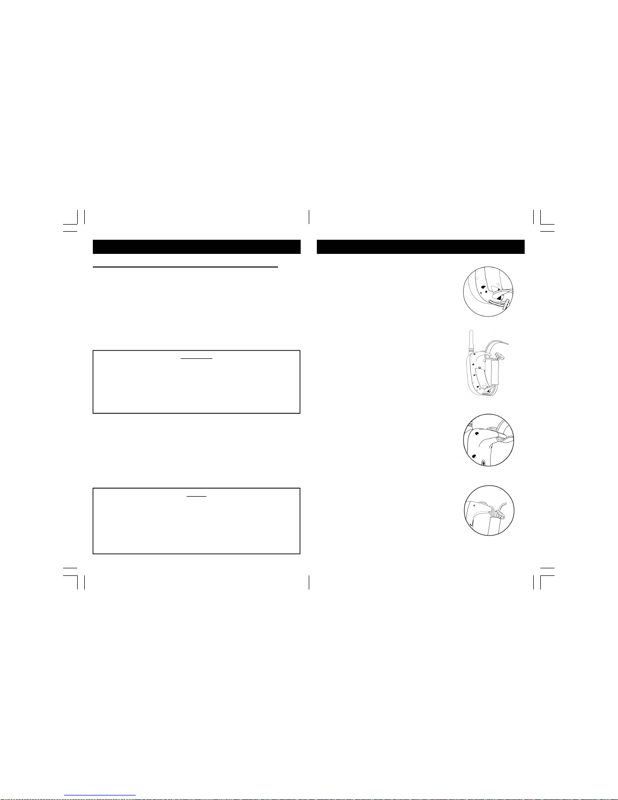
• Re-Thread SureGrip Strap..... 15
• Programming the Collar......................................16
• Properly Fitting the Collar ................................... 17
• Setting the Intensity Level................................... 18
• Setting the Rapid Access Button ........................ 19
• Maintenance ....................................................... 20
• Important Safety Notes .......................................21
• Warranty ............................................................. 22
• FCC/IC/CE Compliance......................................23
• Contact Information ............................................24

4
INTRODUCTION
Thank you for purchasing our Rapid Acce Pro Trainer
(R.A.P.T.
TM
) erie remote training collar, the latest in e-
collar technology and ergonomic design. The highlight of
the system is the unique "hands-free" design of the remote
transmitter - the new patented “Rapid Access
TM
" total
control button is easily accessible for instantaneous cor-
rection of your dog and our patented "SureGrip
TM
" strap
securely holds the unit in place - freeing up your hands for
other activities. The compact design offers worry-free op-
eration and the downsized collar unit means worry-free
use and freedom of movement for your dog in the field.
The R.A.P.T.
TM
erie features a 1,400 yard range made
possi le y our exclusive MAXX-Range 360 technology to
ensure positive FM signal reception, no matter the terrain.
The R.A.P.T.
TM
1400 e-collar also oasts full waterproof
capa ility of the Collar and the Transmitter (the Transmit-
ter even floats just in case it ever goes over oard).
The Gentle Touch feature (with 16 levels of stimulation)
easily adjusts at your fingertips and always ensures the
proper setting for your dog's unique personality. The
R.A.P.T 1400 also features Vi ration Assist and Jump
Stimulation.
Our Vi ration Assist lends a helping hand in the form of an
audi le vi ration emitted from the collar to aid in training
for a no-shock alternative stimulus.
The new D.T. Systems R.A.P.T.
TM
1400 collar is the result
of over 30 years of experience researching, producing,
and field testing the est E-collars in the usiness.
D.T. Sy tem . Dog Te ted, Dog Tough Since 1983.
21
IMPORTANT SAFETY NOTES
•
Before training with this unit, your dog’s health
should e examined y a veterinarian.
•
Do not use with aggressive-tempered dogs.
•
••
•
Your R.A.P.T. Serie
TM
collar is a very valua le tool
if used correctly. It is extremely important that you
completely understand all the functions of the collar
and how to properly train with it efore placing it on
your dog.
•
Test your system efore placing the collar unit on
your dog(s) to help prevent possi le interruptions
and inconsistencies during training and field time.
•
Never leave your dog unattended with the unit
on. Since no electronic device is perfect, there is a
very slight possi ility that your dog may receive an
unintentional electric stimulation.
•
To prevent neck irritation , the collar hould
never be worn for more than 12 hour a day.
Changing the collar location on the dog’s neck daily
will also help prevent irritations. It is recommended
to reposition the collar every 1-2 hours of use.
•
It is important to keep the collar clean. Clean the
electrodes regularly with a mild anti- acterial soap.
•
If an irritation is found, carefully wash the dog’s neck
with soap and water and then wipe the area with
Hydrogen peroxide. Dry thoroughly and apply an
anti iotic ointment. If condition persists eyond 48
hours, please consult a veterinarian.

20
MAINTENANCE
It is very important to periodically clean your R.A.P.T.
Serie
TM
system for maximum performance. Regular
cleaning will also lengthen the life of your unit.
•
Clean the collar ox, elt and uckle with lukewarm
water and a mild anti- acterial soap.
•
Thoroughly clean the space etween the electrodes
and the elt.
•
Always allow the entire unit to completely dry efore
charging/using.
NOTE - The Collar Unit should e rinsed with fresh, clean
water after use in wet conditions, especially salt water.
Battery Maintenance
To get the maximum performance and life out of your
rechargea le atteries:
•
Remove the unit from the charger as soon as the
SmartLED turns green during a charging session.
•
It is recommended not to leave your unit charging
for more than 12 hours at a time.
When storing your unit for extended periods of time:
•
Remove the 9V attery from the Transmitter.
•
Do not store your Collar Unit with depleted atteries.
•
Fully charge and test your unit a out once a month.
•
Do not store your unit in extreme temperatures.
•
Store your unit in a dry environment.
CAUTION
Dispose of atteries properly y calling your local
waste service.
5
PACKAGE CONTENTS
• Transmitter with Antenna and Lanyard
• Collar Receiver
• NiMH Batteries for Collar (already installed)
• Battery Charger
• Triple-Jack Splitter/Adaptor Ca le for charging
• Test Light
• Owner’s and Training Manuals
• PATENTED Curved Transmitter for one finger operation
• Programma le “Rapid Access
TM
” utton
• Small, Compact, Lightweight, “Hands-Free” design
• Multiple Grip options for am idextrous use
• 1,400 Yard (3/4 Mile) range (MAXX-Range 360)
• 16 levels of stimulation (Gentle Touch)
• Vi ration Assist
TM
Technology and “Jump
TM
” Stimulation
utton
• 3-dog expanda le
• Waterproof collar (rechargea le NiMH att)
• Waterproof floating Transmitter unit (9V attery)
• SmartLED
TM
charging and attery life status indicator
• Magnetic On/Off
• Safety Lockout feature on Transmitter
• MAXX-Range™ Internal Antenna System
MODEL FEATURES

6
Tran mitter
PARTS & FUNCTIONS
Jump Button
SureGrip
Strap
Battery Cover
Rapid Acce Button
(default Nick Stim.) LED Indicator Light
Continuou
Stimulation Button
Collar Selector Dial
with Lockout
Vibration Button
Antenna
Tran mitter Antenna - Always check that the
Antenna is securely fastened to the transmitter efore
each use. Hand tighten only. Use caution when
attaching Antenna as over-tightening may cause
damage to the Antenna or antenna mount.
Inten ity Level Dial
Lanyard Connection
Magnet ON/OFF
Switch (white dot)
19
SETTING THE INTENSITY LEVEL
Setting the Jump Stimulation Level (cont.):
1. Press and hold Button Jump utton.
2. While holding the Jump utton, turn the Intensity Dial to
the desired Jump stimulation level. The LED will start
flashing to indicate that you are programming the Jump
stimulation level
3. Release the Jump utton. The LED will flash the num-
er of the new Jump level to confirm successful Jump
level programming.
The Jump intensity setting will stay at this level until a differ-
ent Jump level is programmed. Changing your normal in-
tensity level will not affect the Jump setting. When applying
the Jump stimulation, the intensity level will return to its nor-
SETTING THE RAPID ACCESS BUTTON
The Rapid Access Button’s default setting is Nick Stimulation.
However, you can set it to e Continuous Stimulation, Vi ration, or
Locate (varies with model).
1. Set Collar Selector Dial in the Lockout position (upper-most
solid dashed line).
2. Turn Intensity Dial to 1 (Nick), 2 (Continuous), 3 (Vi ration), or
4 (Locate). See Below .
3. Press and hold the Rapid Access Button and Jump Button
simultaneously until the LED turns on.
4. Release uttons. The LED will flash 1 to 4 times depending
on chosen setting as confirmation.
Intensity Dial Setting Rapid Access Button Setting
Level 1 Nick (default)
Level 2 Continuous
Level Vibration

18
SETTING THE INTENSITY LEVEL
It is very important to set the correct intensity level on
your R.A.P.T. Training System efore eginning your
training sessions to provide the proper level of
stimulation without over-stimulating your dog.
1. Place the Intensity Selection dial so that the system
is set on Level 1.
2. Turn on the Collar Receiver and then fit it properly
around your dog’s neck.
3. Press the ‘Cont.’ utton and check for a reaction.
Indications of your dog feeling the stimulation
include confusion on it’s face, ears perking up,
changes in tail movements, etc.
4. If there are no signs of your dog feeling the
stimulation, increase the Intensity Level in
increments of one until your dog reacts to the
stimulation.
5. At this point, increase the Intensity Level y one or
two. This should e your dog’s ideal training level.
NOTE
Some dogs may require more or less stimulation depending
upon their individual temperament and/or size.
Setting the Jump Stimulation Level:
CAUTION: To avoid accidentally stimulating your dog,
please make sure that the collar is NOT on the dog
while setting the jump level.
7
Inten ity Selection Dial - The
intensity selection dial can e set from
level 1 to level 16 to find the exact
stimulation level for your dog (see
page 18).
LED Indicator Light - The LED lights while pressing
any of the Transmitter uttons. The LED flashes
rapidly after pressing a utton if the attery is low,
PARTS & FUNCTIONS
Continuou Stimulation Button - Pressing this
utton emits a continuous stimulation while the utton
is eing pressed (up to an 8 second safety cutoff).
Collar Selector Dial with Lockout - Switching
etween collar units can e controlled y toggling the
Collar Selecting Switch to the desired unit. Lockout
position prevents accidental utton activations.
Lockout position is the upper-most position that is a
solid dash line.
Battery Cover (Back of Tran mitter) - Covers
attery and attery compartment. Held y 2 small
Phillips screws.
Rapid Acce Button - Default setting is ’Nick’
Stimulation, which makes the collar emit a quick, split-
second stimulation. This utton can e programmed
to e different functions as well (see page 19).
SureGrip Strap - Allows Transmitter to e worn on
hand for “hands-free” operation.

8
PARTS & FUNCTIONS
Vibration and Jump Button - Pressing the Vi ration
Button makes the collar vi rate only. Pressing the
Jump Button makes the collar give a ‘Jump’ Stimula-
tion, making the intensity level instantly “jump” to a
user-programmed intensity level (see page 18).
Lanyard Connection - Point of attachment for
lanyard.
Magnetic ON/OFF Switch - White dot on Transmitter
indicating location of the magnet used to power ON/
OFF the Collar Unit.
17
PROPERLY FITTING THE COLLAR
NOTE: Proper collar tightness and
position are very important to insure
safe and consistent collar use.
All electronic collars need to e
very snug around the dog’s neck
to work properly. They must e
just tight enough to allow the
“contacts” or electrodes to make good contact on your
dog’s skin. If the collar is too loose, the stimulation
may not work properly ecause good/consistent skin
contact is not eing achieved. This can directly affect
the performance of the collar unit and whether or not
the dog will receive the stimulation. Always check for
good contact to the skin if it appears that your dog is
not responding to the stimulation. A loose collar can
also result in skin irritations from moving or ru ing
too much against your dog’s neck while they are
running or training. A proper fit will help prevent this
from occurring.
•
Place the collar unit high and tight on your dog’s
neck with the collar receiver ox centered elow the
neck. Placing it at the wider ase of the neck can
let it travel up to the narrower part of the neck while
your dog is moving, loosening as it goes.
•
It should e tight enough to fit two fingers etween
the collar elt and your dog’s neck, ut not tight
enough to restrict your dog’s reathing.

16
PROGRAMMING THE COLLAR
When adding an “Add-On” collar, the collar will need to
be programmed to the tran mitter. If your current collar
unit i not re ponding to the tran mitter, it may al o
need to be reprogrammed to the tran mitter.
1. Select the desired Collar Selecting Switch position
on the transmitter.
2. Hold the Transmitter Magnet Indicator (white dot)
directly against the Magnetic Activation Switch (small
ump) on the right side of the Collar Receiver.
3. The SmartLED light inside the Collar Receiver will
light up solid for a out 1 second, followed y 6
flashes. You must keep the Transmitter next to the
Collar Receiver during this time.
4. Continue to hold the Transmitter against the Collar
Receiver until the SmartLED light stays on solid. The
Collar Receiver is now in the Code Running Mode (the
SmartLED light will stay lit for approximately 8
seconds while it is in this mode).
5. Remove the Transmitter from the Collar Receiver
and press the Rapid Access and CONT uttons
simultaneously while it is in the Code Running Mode.
6. When the SmartLED links 3 times, the Collar ID
is programmed and the Collar Receiver is now ON.
NOTE – Do not move the Tran mitter Magnet ON/OFF
witch from the Collar Receiver Magnetic Activation
Switch until after the SmartLED top fla hing and
tay on olid or the Collar Receiver will not go into the
Code Running Mode. You mu t pre the NICK and
CONT button imultaneou ly while the SmartLED i lit
olid.
9
Collar Receiver
PARTS & FUNCTIONS
Contact - Contacts should fit snugly against the
dog’s neck to ensure good contact with the skin. For
more information on the proper fit of the collar, see
page 17.
Charging Receptacle
SmartLED
Indicator Light
Magnetic ON/OFF
Activation Switch
Contact
Collar Belt with
MAXX-Range™
360 Antenna
Collar SmartLED Indicator Light - Shows charging
status and attery life status (see page 11).
Magnetic ON/OFF Activation Switch - Raised dot
turns the Collar Receiver unit ON and OFF (see page
13).
Buckle
Unit Dimen ion Weight
Transmitter 4 1/2” x 2 1/8” x 1” 3.8 oz.
Collar Receiver
4.7 oz. (with elt)
6.1 oz. (with eeper elt)
2 5/8” x 2” x 1 1/2”
Transmitter and Collar Unit Specifications

10
PARTS & FUNCTIONS
CAUTION
If the collar elt is too long, we recommend looping the ex-
cess collar elt ack around through the uckle. We DO
NOT recommend cutting the collar elt. Cutting the collar
elt too short can drastically reduce the range of your collar
unit. However, the collar elt can e cut up to a out 3
inches without affecting the range too much.
Collar Belt with MAXX-Range™ 360 Antenna - The
em edded MAXX-Range™ Antenna is woven into the
collar elt and runs along the entire length of the elt,
providing extended range without the draw ack of an
external antenna. Because it wraps around the neck
along with the collar elt, the MAXX-Range Antenna
provides 360˚ degrees of signal reception and is not
locked y your dog’s ody, regardless of which
direction your dog is facing.
NOTE
The unit is still waterproof even if water gets into the charg-
ing receptacle. However, if water should get in, we recom-
mend rinsing out the charging receptacle and allowing it to
dry, especially after use in salt water. This will prevent pre-
mature corrosion in the metal pins inside that make contact
with the charger plug.
Battery Charging Receptacle - The charger ca les
plug into the Charging Receptacle for recharging
(located on the side of the Collar Receiver facing the
dog’s neck). After charging, always close the Charg-
ing Receptacle with the ru er plug to prevent
foreign particles from getting inside the unit.
15
Re-Thread SureGrip Strap
1. With the buckle of the strap fac-
ing outwards, thread the suregrip
strap through the bottom guide.
2. Thread both sides of the sure-
grip strap through the neoprene
. Thread loose end (non-buckle
end) of the strap through the top
4. Thread loose end through the
top-portion of buckle as shown.

14
To Te t the Vibration:
1. Press Vi rate Button on the transmitter and the col-
lar unit will vi rate only.
Before te ting, make ure that both unit are fully
charged and the power to the Collar Receiver i “ON”.
To Te t the Electronic Stimulation:
1. Place the tester firmly on the contacts
of the Collar Receiver.
2. Set the intensity (note - an intensity
level setting of 4 or less might not e
enough to light the tester).
3. Push the ‘NICK’ or ‘CONT’ utton.
4. The tester light will quickly flash once when the Nick
utton is pushed and light repeatedly when the
Continuous Stimulation utton is pushed (the test
light will e righter at higher intensity levels).
TESTING
To Te t the Jump:
1. Press Jump Button on the transmitter and test light
rightness will reflect the user-programmed Jump
level (see page 19).
2. The intensity level will return to its original setting
when the Jump utton is released.
NOTE: If the collar unit is not responding to any signals
from the transmitter, the collar may need to e repro-
grammed to the transmitter (see page 16).
11
SmartLED
**Charging Error - If the SmartLED has a long link every other
second while charging, the rechargea le attery pack may need to
e replaced. New atteries may also initially give an error light.
Contact D.T. Systems if the pro lem persists after a few charging
sessions.
R.A.P.T. Serie collar units are equipped with the SmartLED
attery status system. The SmartLED system lets you know when
the unit is charging and when the charging is complete. It also
gives you a status on how much charge is remaining in the attery
during use, when it needs charging, and when the atteries will
need to e replaced.
Action LED COLOR/
PATTERN Statu
Charging
(collar only)
Red Charging
Green Charging complete*
Long Red link every
other second Charging error**
Flashing Green 51%-100% charge left
Flashing Red 21%-50% charge left
Red dou le flash or
rapid flash
Battery charge is low and
requires charging soon
While Unit
is On
(collar only)
*Charging Complete - Once charging is complete, your unit will
go into a trickle charge to prevent overcharging. However, it is
recommended that you remove your unit from the charger as soon
as charging is complete.
Tran mitter Battery Indicator - The LED lights while pressing
any of the Transmitter uttons. The LED flashes rapidly after
pressing a utton if the attery is low.

12
CHARGING THE BATTERIES
All R.A.P.T. Serie
TM
collar units are equipped with
rechargea le Nickel Metal Hydride (NiMH) atteries,
which are not memory sensitive and do not require
depletion efore recharging. Although atteries come
partially charged from the factory, it is recommended
that they are given a full charge (a out 12 hours)
efore initial use.
Battery Charging Procedure
1. Make sure the unit is off.
2. Plug the charger into a
standard electrical outlet.
3. Connect the Triple-Jack Ca le to the end of the
charger and plug the end into the collar unit. The
SmartLED should light solid red while charging.
Additional Collar Units can e charged
simultaneously with the Triple-Jack Ca le.
4. Charging is complete when the SmartLED turns
green (may take up to 12 hours).
5. When charging is complete, disconnect the attery
charging ca les from the receptacles, securely
replace the ru er attery receptacle covers, and
test unit.
ARNING: DO NOT CHARGE HILE UNIT IS ET!
NOTE
Rechargea le atteries typically last a out 2-5 years on
average depending on use and care. Keep atteries away
from flamma le su stances. See page 20 for more infor-
mation on attery maintenance.
13
TURNING ON AND OFF
The Transmitter is always in a permanent sleep state.
It is only ON when a utton is eing pressed and does
not need to e turned off y the user. If the
Transmitter does not activate, make sure you have a
good attery installed and that your Collar Selector
Dial is not in the Lockout position.
Turning the Collar Unit ON/OFF:
Turning the Collar Unit ON and OFF uses the same
procedure:
1. Hold the Transmitter Magnet Indicator (white dot)
directly against the Magnetic Activation Switch
(small bump) on the right side of the Collar Unit.
2. The SmartLED Indicator will light solid for a
second and then start flashing. Remove the
Transmitter from the Collar Unit when the
SmartLED light egins to flash.
If the Collar Unit has een turned ON, the SmartLED
will flash approximately every other second. If the
Collar Unit has een turned OFF, the SmartLED will
no longer e flashing.
NOTE
If the LED on the Transmitter flashes red rapidly after any
utton is pressed, the 9V attery will need to e replaced.
If the SmartLED on the Collar Unit dou le-flashes red every
other second while ON, the unit will need to e recharged.
If this happens soon after a full charging session, the re-
chargea le atteries in the Collar Unit may need to e re-
placed.
This manual suits for next models
1
Table of contents
Other D.T. System Pet Care Product manuals

D.T. System
D.T. System Micro-iDT PLUS Series User manual

D.T. System
D.T. System Micro-iDT PLUS Series User manual

D.T. System
D.T. System SPT 2420 User manual

D.T. System
D.T. System EZT 1000 User manual

D.T. System
D.T. System H20 1810 Series User manual

D.T. System
D.T. System Micro-iDT Z3000 User manual

D.T. System
D.T. System ULTRA MIN-E 2090 User manual