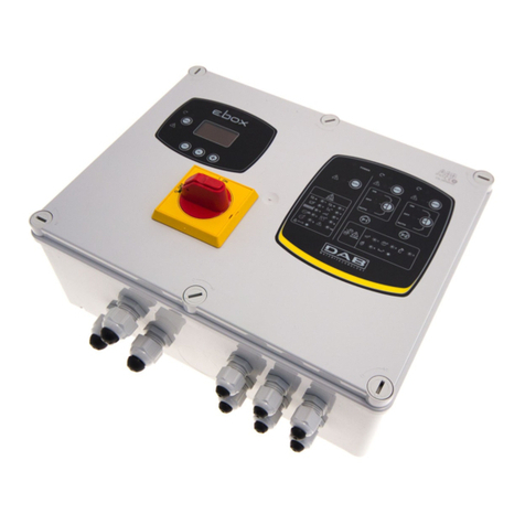
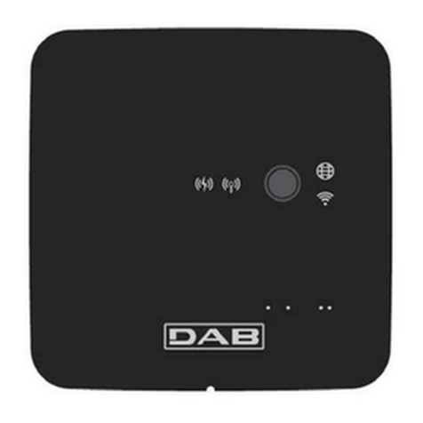
DAB ESY I/O Operating and maintenance manual

ISTRUZIONI PER L'INSTALLAZIONE E LA MANUTENZIONE (IT)
INSTRUCTIONS FOR INSTALLATION AND MAINTENANCE (GB)
INSTRUCTIONS POUR L´INSTALLATION ET LA MAINTENANCE (FR)
INSTALLATIONS- UND WARTUNGSANLEITUNGEN (DE)
INSTRUCCIONES DE INSTALACIÓN Y MANTENIMIENTO (ES)
INSTRUCTIES VOOR INSTALLATIE EN ONDERHOUD (NL)
ИНСТРУКЦИЯ ПО МОНТАЖУ ИТЕХНИЧЕСКОМУ ОБСЛУЖИВАНИЮ (RU)
POKYNY K INSTALACI A ÚDRŽBĚ (CZ)
INSTRUKCJA MONTAŻU I KONSERWACJI (PL)
INSTRUÇÕES PARA A INSTALAÇÃO E A MANUTENÇÃO (PT)
ASENNUS- JA HUOLTO-OHJEET (FI)
INSTALLATIONS- OCH UNDERHÅLLSANVISNING (SE)
INSTRUCŢIUNI PENTRU INSTALARE ŞI ÎNTREŢINERE (RO)
ΟΔΗΓΙΕΣ ΓΙΑ ΤΗΝ ΕΓΚΑΤΑΣΤΑΣΗ ΚΑΙ ΤΗ ΣΥΝΤΗΡΗΣΗ (GR)
KURMA VE BAKIM BİLGİLERİ (TR)
INSTALLÁCIÓS ÉS KARBANTARTÁSI KÉZIKÖNYV (HU)
ИНСТРУКЦИЯ ЗА МОНТИРАНЕ ИПОДДРЪЖКАТА (BG)
ﺔﻧﺎﯿﺼﻟاو ﺐﯿﻛﺮﺘﻟا تﺎﻤﯿﻠﻌﺗ)ﺔّﯿِﺑَﺮَﻌﻟا ﺔﻐﻠﻟا(
ESY I/O

Manuale valido per le versioni firmware 1.x.x
(IT)
Manual valid for firmware versions 1.x.x
(GB)
Manuel applicable aux versions de firmware 1.xx
(FR)
Für Firmware 1.x.x gültiges Handbuch
(DE)
Manual válido para las versiones de firmware 1.x.x
(ES)
Handleiding geldig voor firmwareversies 1.x.x
(NL)
Руководство действительно для версий программы 1.x.x
(RU)
Návod platí pro verze mající firmware 1.x.x
(CZ)
Instrukcja ważna dla wersji firmware 1.x.x
(PL)
Manual válido para as versões firmware 1.x.x
(PT)
Käyttöopas laiteohjelmaversioille 1.x.x
(FI)
Bruksanvisning för programvaruversioner 1.x.x
(SE)
Manual valabil pentru versiunile firmware 1.x.x
(RO)
Το εγχειρίδιο αυτό ισχύει για τις εκδόσεις firmware 1.x.x
(GR)
1.x.x donanım yazılımı (firmware) sürümleri için geçerli kılavuz
(TR)
1.x.x Firmware verziókra érvényes kézikönyv
(HU)
Ръководство, валидно за версии на фърмуера 1.x.x
(BG)
(AR) ﺔﺗﺑﺎﺛﻟا ﺞﻣارﺑﻟا تارادﺻﻹ ﺢﻟﺎﺻ لﯾﻟد1.x.x

2
ITALIANO
pag.
01
ENGLISH
page
13
FRANÇAIS
page
25
DEUTSCH
seite
37
ESPAÑOL
pág.
49
NEDERLANDS
pag.
61
РУССКИЙ
стр.
73
ČEŠTINA
strana
85
POLSKI
strona
97
PORTUGUÊS
pag.
109
SUOMI
sivu
121
SVENSKA
sid.
133
ROMÂNĂ
pag.
145
ΕΛΛΗΝΙΚΑ
σελίδα
157
TÜRKÇE
sf.
169
MAGYAR
oldal
181
БЪЛГАРСКИ
Стр.
193
205
ﺔﺤﻔﺼﻟا
ﺔﻐﻠﻟاﺔَﯿِﺑَﺮَﻌﻟا

ENGLISH
13
CONTENTS
1. GENERAL ................................................................................................................................................................................... 14
1.1 Content of the pack.................................................................................................................................................................. 14
1.2 Applications.............................................................................................................................................................................. 14
2. INSTALLATION........................................................................................................................................................................... 14
2.1 Electrical connections...................................................................................................................................................... 15
2.2 Product characteristics .................................................................................................................................................... 16
2.3 User interface .................................................................................................................................................................... 16
2.4 Local connection via APP ................................................................................................................................................ 17
2.5 Updating the software ...................................................................................................................................................... 17
2.6 Dab Proprietary Wireless connection ............................................................................................................................. 17
2.7 Optoisolated digital inputs............................................................................................................................................... 18
2.8 Output contacts................................................................................................................................................................. 19
2.9 Remote pressure sensor.................................................................................................................................................. 20
2.10 RS485 Modbus RTU connection...................................................................................................................................... 21
2.11 Fault management ............................................................................................................................................................ 23
3. PROBLEM SOLVING.................................................................................................................................................................. 24
KEY
The following symbols have been used in the discussion
SITUATION OF GENERAL DANGER.
Failure to respect the instructions that follow may cause harm to persons and property.
SITUATION OF ELECTRIC SHOCK HAZARD.
Failure to respect the instructions that follow may cause a situation of grave risck for personal safety.
Notes and general information.
WARNINGS
The products dealt with in this discussion fall within the category of professional equipment and belong to insulation
class 1.
Read this documentation carefully before installation. Installation and operation must comply with the local safety regulations
in force in the country in which the product is installed. Everything must be done in a workmanlike manner
Failure to respect the safety regulations not only causes risk to personal safety and damage to the equipment, but invalidates
every right to assistance under guarantee.
Skilled personnel
Installation must be carried out by competent, skilled personnel in possession of the technical qualifications required by the
specific legislation in force. The term skilled personnel means persons whose training, experience and instruction, as well as
their knowledge of the respective standards and requirements for accident prevention and working conditions, have been
approved by the person in charge of plant safety, authorizing them to perform all the necessary activities, during which they
are able to recognize and avoid all dangers. (Definition for technical personnel IEC 364)
This appliance can be used by children aged from 8 years and above and persons with reduced physical, sensory or mental
capabilities or lack of experience and knowledge if they have been given supervision or instruction concerning use of the
appliance in a safe way and understand the hazards involved.

ENGLISH
14
Failure to observe the warnings may create situations of risk for persons or property and will void the product guarantee.
Particular warnings
Always switch off the mains power supply before working on the electrical or mechanical part of the system. Before
opening the equipment, wait at least five minutes after disconnecting it from the power supply. Only firmly cabled
mains connections are admissible.
1. GENERAL
ESY I/O is designed to provide the Esyline range of products with optoisolated inputs and outputs, access via BMS systems via MODBUS RTU
Rs485, remote pressure sensor.
ESY I/O is configured and updated via the DConnect APP.
1.1 Content of the pack
- ESY I/O
- Quick Guide.
1.2 Applications
Esy I/O allows the following applications:
• connection to BMS (Build Management Systems) equipped withRS485 MODBUS RTU interface
• Connection with clean contact inputs (e.g. floats)
• Output connection, (e.g. sirens)
• Connection of remote pressure sensor, to compensate for pressure losses
2. INSTALLATION
For the first installation, if wall mounting is necessary, proceed as described below:
1. Remove the front panel by unscrewing the 4
retaining screws with a straight tip
screwdriver.
2.
Drill holes in the wall and insert
fixtures aligned with the panel
columns
3. Remove the clips for tightening the plastic
screws of the panel
Safety
Use is allowed only if the electric system is in possession of safety precautions in accordance with the regulations in force in
the country where the product is installed (for Italy CEI 64/2).
The power supply cable must never be used to carry or shift the device.
Never pull on the cable to detach the plug from the socket.

ENGLISH
15
4. Screw the panel onto the wall
5.
Replace the clips for tightening
the plastic screws of the panel
6. Screw the panel on again
Before screwing the panel back on, make sure that the cable between the two boards is correctly connected!
2.1 Electrical connections
ESY I/O requires the connection of an L-N single-phase power supply cable, the characteristics of which must be as follows:
- Single cable copper section minimum 0.8mm2 (AWG 18)
- Maximum sheath diameter 10mm
- Minimum sheath diameter 5mm
1. Insert the cable in the cable gland shown in Figure 1, circled in orange (Cable gland 3)
Figure 1: Front view of cable glands
2. Connect the power cable before closing the front panel as shown below:
3. Tighten the cable gland to maintain the IP rating of the panel
Depending on the application, the user can make other electrical connections, see Figure 1.
The cable glands in section 1 are used to wire Inputs (see Paragraph 2.7), pressure sensor (see Paragraph 2.9) and Rs485 Modbus (see
Paragraph 2.10).
The cable glands in section 2 are used to wire Outputs (see Paragraph 2.8).

ENGLISH
16
2.2 Product characteristics
The product characteristics are listed below:
- Supply voltage: 100-240 VAC
- Frequency: 50-60Hz
- Rated current (rms) @ 230 VAC: 125 mA
- Optoisolated digital inputs: 4
- Output: 4 NO (Normally open) , max 5A @230VAC
- 1 RS485 (Modbus RTU)
- Working temperature: 0 -50 °C
- Protection rating: IP55
- Radio Modules:
oDAB Proprietary Wireless (IEEE 802.15.4), FFC ID: OA3MRF24J40MA
oWifi (802.11 b/g/n 2.4 GHz)
oBluetooth V4.2 BR/EDR, Bluetooth LE
2.3 User interface
Figure 2: Esy I/O label
On the Esy I/O there are LEDs indicating the system operating status.
Characteristics of the LEDs
Led
Colour
Description
Power
White
On: Esy I/O powered
Off: Esy I/O not powered
Fault
Red
Lit blinking: Error present (see paragraph 2.10)
Off: No error
Pressure
Green
On: Pressure sensor connected
Off: Pressure sensor not connected
Modbus
Green/Red
Steady green: Gateway modbus active
Regular blinking green: Modbus gateway in alignment
Green with temporary blinking: message transmission in progress
Steady red if error (error message, timeout error)
Blinking red: Modbus Gateway alignment error
Off: Gateway modbus not active
Internet
Blue RFU
Bluetooth
Blue
On: Bluetooth connection active
Off: Bluetooth connection not active
Input (4 leds)
Green
On: Corresponding input energised (e.g. contact closed)
Off: Corresponding input not energised (e.g. contact open)
Output (4 leds)
Yellow
On: Corresponding relay closed
Off: Corresponding relay open
Dab Proprietary
Wireless
Blue
On with a fixed light: wireless communication present
On blinking: Network configuration present, but connection not active or not
complete

ENGLISH
17
Off: Wireless network configuration not present
Wifi
Blue
On: Wifi connection present
Blinking: AP mode
Off: Wifi connection not present
Table 1: Led Description
Esy I/O has two touch buttons in the interface (Wireless and wifi). When the touch button is pressed, the corresponding LED blinks rapidly.
The implementation of the commands, described below, is confirmed by a beep.
2.4 Local connection via APP
The “Smart Solution” DConnect APP is the interface for local control of the Esy I/O device. Via the DConnect APP you can update the product
and configure the main parameters of the device with the convenience of an easy-to-use and always handy APP. Via the APP it is possible to
interact locally with the product through the “Direct Connection” menu accessible directly from the main page of the APP.
Figure 3: Dconnect APP main screen
Select the image related to the Esy I/O product, and follow the instructions during the process.
2.5 Updating the software
Updates ensure a better use of the services offered by the product. Before starting to use the product, make sure that it is updated to the latest
software version available. During the software update the products involved cannot carry out their functions. For this reason a manned update
is recommended.
NOTE 1: The update can take up to 5 minutes per product and when it ends the device will restart.
2.6 Dab Proprietary Wireless connection
The basic function of the Esy I/O is that it can be connected by means of a wireless interface 802.15.4, equipped with a DAB proprietary
protocol, to one or more supported e.syline products.
The proprietary wireless connection is also necessary for the alignment to use Esy I/O as Modbus gateway (see Paragraph 2.10 )
Proprietary wireless connection procedure
It is possible to connect the Esy I/O to a device or to several devices using the following procedure:
• Put the device to be connected into association status (see the manual of the product to be associated)
• Press the key on Esy I/O for a least 5 seconds, then wait for the blue led (seeTable 1) to light up with a fixed light.
To interrupt the procedure it is possible to press the left key on the Esy I/O.

ENGLISH
18
In the event of a momentary disconnection of the associated device, the blue LED will flash to indicate that the device is not connected, but is
trying to restore the connection.
The wireless network configuration is maintained even in the case of a temporary power cut or if the device is switched off.
Disconnection procedure and resetting of the wireless configuration.
Hold down the key for 5 seconds. If the operation has been successful the blue LED will be off.
2.7 Optoisolated digital inputs
ESY I/O has the possibility to connect up to 4 optoisolated inputs.
The 4 digital inputs are optoisolated, they can be energised either with continuous negative and positive voltages or with alternating current at
50-60 Hz. Table 2 describes the characteristics and the limits of the digital inputs:
Characteristics of the inputs
DC inputs [V]
AC inputs 50-60 Hz [Vrms]
Minimum switch-on voltage [V]
6.2
4.5
Maximum switch-off voltage [V]
2
1.5
Maximum admissible voltage [V]
40
40
Current absorbed at 12V [mA]
1.4
1.4
Max. accepted cable section [mm²]
1.5
Table 2: input characteristics
The optoisolated terminals are connected by applying a voltage to the terminals or by connecting the common signal to GND as a jumper and
connecting the Insignal to a contact (e.g. float, pressure switch, etc.)
Input wiring
Input connected to clean contact
Voltage input
Input
Clean contact between
pins
Jumper
Connection
I1
I1-V+
C1/2 - CM
I1 – C1/2
I2
I2-V+
C1/2 - CM
I2 - C1/2
I3
I3-V+
C3/4 - CM
I3 – C3/4
I4
I4-V+
C3/4 - CM
I4 – C3/4
Table 3: Input wiring
Below, Figure 4: Example of clean contact connectionFigure 4, an example of clean contact wiring on I1.
Figure 4: Example of clean contact connection
For the configuration of the inputs (e.g. Float Pressure Switch, Disable, etc.), refer to the manual of the device connected to ESY I/O.
The input status is displayed both by the Input LEDs (see Table 1), and on the APP Status page (see Figure 5).

ENGLISH
19
Figure 5: Input Status Page
2.8 Output contacts
The connections of the outputs listed below refer to the terminal board indicated with screen printing O1, O2 and CA.
Table 3 describes the characteristics and limits of the output contacts.
Characteristics of the output contacts
Type of contact
NO (Normally open)
Max. bearable voltage [V]
230 VAC
Max. bearable current [A]
5 -> resistive load
2.5 -> inductive load
Max. accepted cable section [mm²]
2.5
Table 4: Characteristics of the output contacts
The correspondences between relays and outputs are described below:
Label
Corresponding Output
RL6
O1
RL7
O2
RL8
O3
RL9
O4
Table 5: Relay Output correspondence
An example of a connection is shown below, on output O1 with a 230V load.

ENGLISH
20
Figure 6: Example of O1 connection with 230V load
Switching on and off will depend on the settings made on the device/group of devices (see associated product manual).
The output status is displayed both by the Output LEDs (see Table 1), and on the APP Status page (see Figure 7).
Figure 7: Output Status Display
2.9 Remote pressure sensor
The Esy I/O allows the use of 1 remote pressure sensor, directly on the 4-pole connector PR1 (see Figure 8).

ENGLISH
21
Figure 8: Connection of the pressure sensor
The mode of use will depend on the settings made on the device/group of devices (see associated product manual).
Via the Dconnect APP, it is possible to select the sensor used.
Figure 9: Pressure Sensor Setting Page
The following sensors are currently supported:
1) HUBA pressure sensor 0-25 bar
2.10 RS485 Modbus RTU connection
Esy I/O can be used as an RS485 gateway, with MODBUS RTU protocol, in order to perform data monitoring and control on devices supported
by Esy I/O.

ENGLISH
22
Wiring
Modbus communication with 2-wire RS485 contemplates the use of 3 cables (A, B and GND). Connect the 3 cables correctly.
It is recommended to use a screened 2-pole cable, with a twisted pair, adapted to 120 ohm if termination resistors are to be used.
Figure 10: Rs485 Modbus Wiring
MODBUS Terminals
Description
A
Terminal -
B
Terminal +
GND
Reference
Table 6: Description of Rs485 Terminals
The typical connection with an RS485 BUS is shown below.
The recommended connection is always of the Daisy chain type (option 1). Do not use star (option 2) or ring connections. The termination
resistors, if necessary, must be inserted in the first and last device on the bus (e.g. Figure 11: The termination resistors must be inserted in
Master BMS and Device n) Figure 11: Examples of bus wiring.
The maximum recommended number of connected devices is 32, consistent with other devices in the network. The length of the cables
depends on the baud rate chosen, i.e. the higher the baud rate, the shorter the cable length.
Figure 11: Examples of bus wiring
Parameter configuration
Esy I/O parameters are configured via Dconnect APP, connecting point-to-point via smartphone.

ENGLISH
23
Figure 12: APP page for setting Modbus parameters
The characteristics of the Modbus connection are as follows (the options at the first start-up are shown in bold):
Parameter
Description
Settable values
Baud rate (bps)
Transmission speed
2400, 4800, 9600, 19200, 38400, 57600,
115200
Parity
Parity check
No, Even, Odd
Stop bit
Number of stop bits
1.2
Minimum response delay (ms)
Minimum response time (e.g., if 100, Esy I/O will
respond to the message after at least 100ms)
0– 1000
Id
Slave identification (each slave device on the Modbus
network must have a different Id)
1-247
Table 7: Modbus characteristics
For information on Modbus registers that can be consulted and/or modified, refer to the manual of the device connected to Esy I/O.
IMPORTANT! In order to use the Modbus peripheral, enable it via APP by configuring the Modbus Mode parameter.
2.11 Fault management
Table 8 Describes possible faults that may be encountered by Esy I/O.
Fault
FAULT LED
General
On with fixed light
Insufficient supply voltage
1 blink
Pressure sensor error (if sensor use is set)
2 blinks
Internal error
3… 7 blinks
Wireless
8 blinks
Wifi
9 blinks
Table 8: List of faults

ENGLISH
24
3. PROBLEM SOLVING
Before starting to look for faults due to the wiring it is necessary to disconnect the power supply to the pump (take the plug
out of the socket).
Below is a list of possible problems:
Problem
Problem description
Possible solution
Power led off
No power supply
Check power supply wiring
Check for short circuits due to incorrect
wiring
Error Insufficient supply voltage
Board power supply voltage not sufficient
Check for overloads due to incorrect wiring
of sensors, inputs and outputs
Pressure sensor error
Pressure sensor out of range
Check that the pressure sensor connection
is correct (PR1 connector)
Green pressure sensor led not active
Although the pressure sensor is connected,
the led does not work
Make sure the pressure sensor is enabled
(proceed via APP)
Modbus communication not working
If Modbus LED is GREEN:
1)
Check that Modbus is enabled,
via APP (Modbus Mode
parameter = enabled)
2)
Check that Modbus parameters
are correct (Baud rate, parity, stop
bits, ID), via APP
3) Check RS485 wiring
If Modbus LED is RED:
1)
Make sure that wireless
communication between
pump/group and ESY I/O is
active.

DAB PUMPS LTD.
6 Gilbert Court
Newcomen Way
Severalls Business Park
Colchester
Essex
C04 9WN - UK
Tel. +44 0333 777 5010
DAB PUMPS GmbH
Am Nordpark 3
41069 Mönchengladbach, Germany
Tel. +49 2161 47 388 0
Fax +49 2161 47 388 36
DAB PUMPS HUNGARY KFT.
H-8800
Nagykanizsa, Buda Ernőu.5
Hungary
Tel. +36 93501700
DAB PUMPS DE MÉXICO, S.A. DE C.V.
Av Amsterdam 101 Local 4
Col. Hipódromo Condesa,
Del. Cuauhtémoc CP 06170
Ciudad de México
Tel. +52 55 6719 0493
DAB PUMPS OCEANIA PTY LTD
426 South Gippsland Hwy,
Dandenong South VIC 3175 – Australia
Tel. +61 1300 373 677
DAB PUMPS B.V.DAB PUMPS B.V.
Albert Einsteinweg, 4Albert Einsteinweg, 4
5151 DL Drunen - Nederland5151 DL Drunen - Nederland
Tel. +31 416 387280Tel. +31 416 387280
Fax +31 416 387299Fax +31 416 387299
DAB PUMPS BVDAB PUMPS BV
‘tHofveld 6 C1‘tHofveld 6 C1
1702 Groot Bijgaarden - Belgium1702 Groot Bijgaarden - Belgium
Tel. +32 2 4668353Tel. +32 2 4668353
DAB PUMPS IBERICA S.L.DAB PUMPS IBERICA S.L.
Calle Verano 18-20-22Calle Verano 18-20-22
28850 - Torrejón de Ardoz - Madrid28850 - Torrejón de Ardoz - Madrid
SpainSpain
Tel. +34 91 6569545Tel. +34 91 6569545
Fax: + 34 91 6569676Fax: + 34 91 6569676
DAB PUMPS INC.
3226 Benchmark Drive
Ladson, SC 29456 - USA
Tel. 1- 843-797-5002
Fax 1-843-797-3366
OOO DAB PUMPS
Novgorodskaya str. 1, block G
office 308, 127247, Moscow - Russia
Tel. +7 495 122 0035
Fax +7 495 122 0036
DAB PUMPS (QINGDAO) CO. LTD.
No.40 Kaituo Road, Qingdao Economic &
Technological Development Zone
Qingdao City, Shandong Province - China
PC: 266500
Tel. +86 400 186 8280
Fax +86 53286812210
DAB PUMPS S.p.A.
Via M. Polo, 14 - 35035 Mestrino (PD) - Italy
Tel. +39 049 5125000 - Fax +39 049 5125950
www.dabpumps.com
DAB PUMPS SOUTH AFRICA
Twenty One industrial Estate,
16 Purlin Street, Unit B, Warehouse 4
Olifantsfontein - 1666 - South Africa
Tel. +27 12 361 3997
DAB PUMPS POLAND SP. z.o.o.
Ul. Janka Muzykanta 60
02-188 Warszawa - Poland
02/21cod.60202789
Table of contents
Other DAB Control Unit manuals
Popular Control Unit manuals by other brands

Kieback&Peter
Kieback&Peter FSM21 Device description

Paradox
Paradox Spectra 1759EX V1.0 Reference & installation manual

IBC control
IBC control VariMax25 manual

Krom Schroder
Krom Schroder JSAV operating instructions

Fantini Cosmi
Fantini Cosmi CH193VMC Instructions for use

Keyautomation
Keyautomation 900CT-24M instruction manual