DAC Limited 711 Series User manual

GENERAL CARE AND MAINTENANCE
The 711 telephone does not require any regular maintenance.
To clean the telephone wipe with a damp cloth.
Do not use any abrasive cleaners on the telephone as this
may cause the product to become discoloured.
DAC LIMITED
Distributed by:-
USER GUIDE
Vandal Resistant Telephones
DAC Limited
214a Lomeshaye Business Village
Turner Road
Nelson, Lancashire, UK
BB9 7DR
T +44 (0) 1282 447000
F +44 (0) 845 2801915
www.daclimited.co.uk
711 Full Keypad Telephone

CONTENTS
Page 2 Approved Facilities
Page 3 Electrical Installation
Page 4 RA711 PCB [Key components]
Page 5 Installation
Page 7 Set Up Features
Page 8 Setting up Expansion Board
Page 11 General Care and Maintenance
Page 1
THIS PAGE LEFT BLANK INTENTIONALLY

Approved Facilities
This telephone is designed to operate via a standard
analogue telephone PBX or exchange. Any other usage will
invalidate the approval of the apparatus and as a result it
then ceases to comply with the standards against which
approval was granted.
Connection is affected by plugging in to an appropriate line
connection via the LINE connection terminal as described in
the section marked ELECTRICAL INSTALLATION. If in any
doubt please contact your telephone installer or network
supplier.
It is assumed that this equipment will be installed by a
qualified telephone installer, incorrect installation will
invalidate any warranty. If you are in any doubt regarding
network connectivity or operation please contact your
supplier or network manager. Correct installation and
connection of this apparatus is mandatory as failure to
install and connect correctly will invalidate any approval
given to this apparatus.
Technical assistance, if necessary, is availble from DAC
direct by telephoning +44 (0) 1282 447000.
*1*nn Where nn represents the PIN/command
mode timeout value 01-99 seconds (10
seconds default)
*2*nn Where nn represents the voltage free
contact energise time value 01-99 seconds
(2 seconds default)
*3*xxxxyyyy Where xxxx is the current PIN and
yyyy is the new PIN (xxxx = 1234 default)
*4*n Where n represents the PIN entry mode
loudspeaker mute status 0 - disabled or 1 -
enabled (1 default)
Example: * 1 * 1 5 = PIN/command timeout set to 15
seconds
Example: * 3 * 1 2 3 4 9 4 2 6 = PIN set to 9426 from
default
ELECTRICAL INSTALLATION
Line Terminal Connections and Selections
When populated, the Terminal block mounted at the back of the
unit is labelled as follows:-
1. Load
2. Load
Connect the load (0 Volts) to the terminal block marked 1 and
2.
This is the output from the relay which is energised upon pin
entry.
Page 9 Page 2

ELECTRICAL INSTALLATION
Line Terminal Connections and Selections
The number of telephones that can be connected to a direct
exchange line or PBX extension is limited by the ringer
equivalence number (REN) of all the telephones connected, this
should not exceed a total value of 4.
The REN value of this telephone is 1. In case of doubt consult
your telephone supplier.
The Terminal block mounted at the back of the unit is labelled as
follows:-
A. (A)
ER. Earth when using
Earth Recall
B. Line (B)
Connect the telephone line to the wires marked A and B. If you
are to use Earth Recall then also connect the earth wire to the
terminal marked ER.
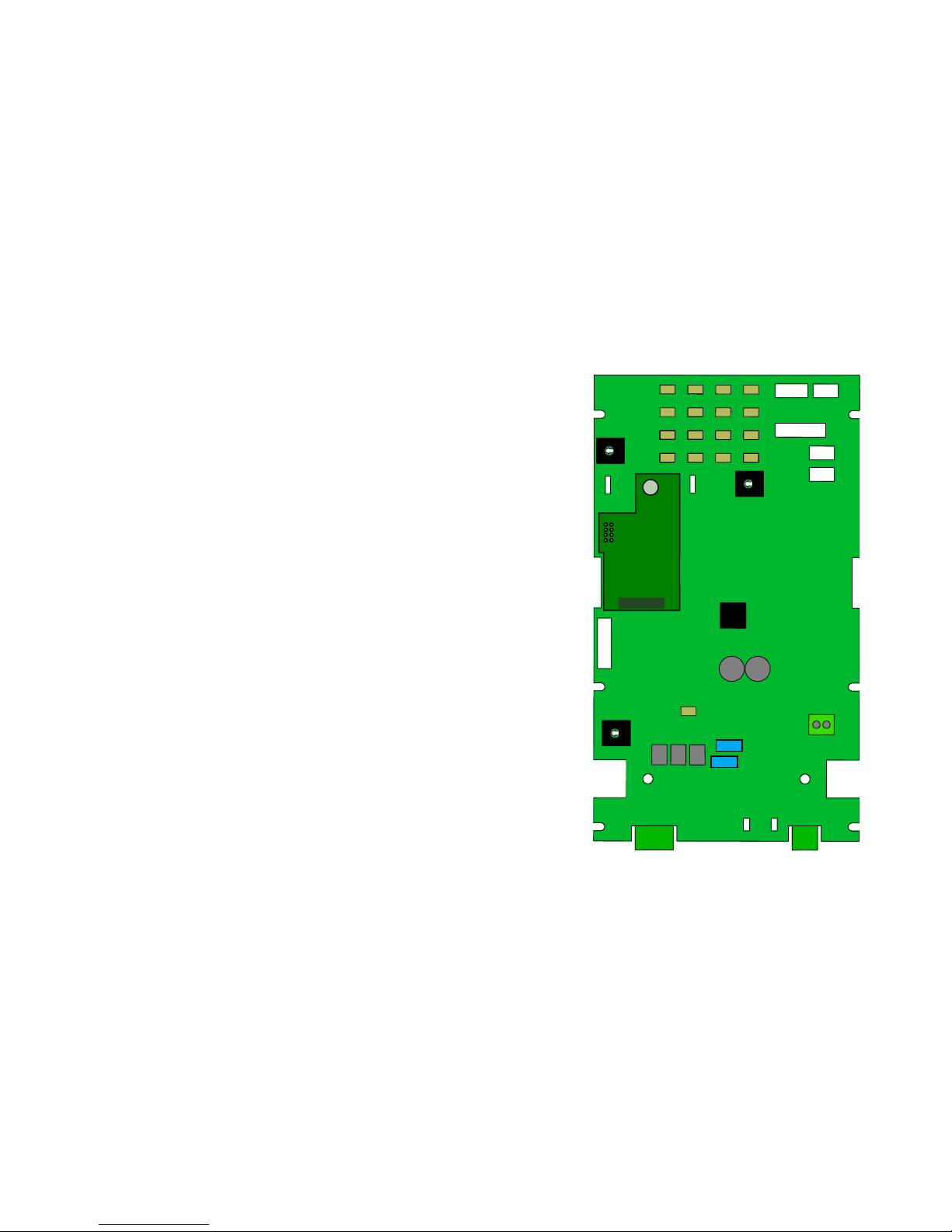
Once the line is connected please allow 30 seconds for the
phone to completely power up before trying to use it. If
the phone does not power up you can also press the small
button labelled ‘BOOT’, located on the rear of the phone
near to the bottom of the Circuit board.
Page 3
SETTING UP THE EXPANSION BOARD.
Overview.
The DAC DTMF controller expansion board product consists of a
Printed Circuit Board (PCB) which can be attached to the DAC
range of telephone products which feature an expansion port.
The PCB provides a DTMF decoder and controller which allow a
voltage free contact to be energised.
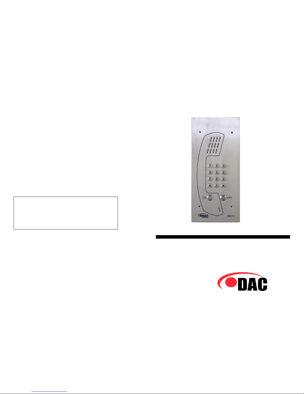
Pin entry mode.
The product waits for the DTMF tone representing ‘#’ (hash) and
enters PIN entry mode. The loudspeaker on the RA711
(handsfree) telephone is muted (default, see below) while
another four (4) DTMF tones (digits) are entered, which
represent the PIN code, before the loudspeaker is de-muted. A
comparison is made between the four (4) digits entered and the
currently configured PIN code (default 1234, see below) and if
found to be the same the voltage free contact is energised for a
period of two (2) seconds (default, see below). Should entry of
the four (4) PIN digits be interrupted or incomplete then PIN
entry mode is aborted after a period of ten (10) seconds
(default, see below) and the loudspeaker de-muted.
Example (default PIN): # 1 2 3 4 = contact energised for 2
seconds.
The product also features an override mode which can be used to
immediately de-energise the voltage free contact. After entering
the PIN in the normal manner to energise the contact, a second
sequence consisting of a ‘#’ (hash) digit followed by a second ‘#’
(hash) digit is entered and the contact is immediately de-
energised.
Command mode. [Please note that telephone needs to be off
hook when entering these commands]
The product waits for the DTMF tone representing ‘*’ (star) and
enters command mode. Four (4) commands are available to
allow product configuration, as follows:
Page 8

HF GAIN
HANDSET
HKSW
HFBUTS
HFHLS
HFLLS
LOAD
1 2
LINE
A ER B
+ -
POWER
TMR
TYPE
NRM
MIC
ENABLE
DISABLE
HS LOOP
LP GAIN
KEYPAD
HK TIME
DIAL BREAK
MF
LD
TBR
ER
BOOT
ON HK
R/P
PG
MR
V+ V-
M1 M2 M3
RA711 Printed Circuit Board
CN13
Page 4
DTMF CONTROLLER
SETTING UP THE 711 FEATURES.
Volume.
To adjust the volume of the speaker use the V+ and V- keys on
the rear of the phone. The volume once set will remain at the
user set level until it is re adjusted.
Call termination settings.
Call termination can be by pressing the off button on the front of
the telephone [if available], by tone detection or preset timer.
Timer
To select preset timer place the link provided on the header
marked TMR TYPE on to the NRM setting, then select a duration
for maximum call length by adjusting the potentiometer marked
HK TIME (variable between 1 -10 minutes). Function can be
disabled by turning the potentiometer fully anti clockwise.
Tone detection
To select the tone detection option place the link provided on the
header marked TMR TYPE on to the NRM setting. This will
automatically clear the line at the end of a call by detecting the
tones on the line.
TBR recall- Take the link and place it onto the header marked
BREAK placing it on the TBR link.
ER recall- Take the link and place it onto the header marked
BREAK placing it on the ER link.
Dialling modes
The telephone has selectable links for the different dialling and
recall modes. These are selected by placing the links onto the
relevant headers at the bottom of the board.
Dial modes
MF dialling- Take the link and place it onto the header marked
DIAL placing it on the MF link.
LD dialling- Take the link and place it onto the header marked
DIAL placing it on the LD link.
Recall modes
Page 7

Wall Surface Installation
1. Fix the surface
mounting back box to the
wall, with cut-out at the bottom,
using size 8 or 10 screws with
rawplugs (4 off).
2. Connect the cabling, as
detailed under Electrical
Connections, and then fit to the
back box (as described under Wall
Flush Installation, item 3).
3. Use any suitable silicone
waterproofing sealant (such as
Unibond Waterproof Flexible
Frame Sealant) to seal to the back
box. Leave a 12mm to 13mm
(0.5") gap at the bottom for
drainage.
Top-of-pole Installation
1. Place the top-of-pole
mounting over the top of the
pole.
2. Tighten the grub screws
to secure the mounting.
3. Fix the surface mounting
back-box to the top-of-pole
mounting with the screws
provided.
4. Connect the cabling, as
detailed under Electrical
Connections, and then fit to the
back-box (as described under
Wall Flush Installation, item 3).
Page 6
INSTALLATION
The following information is provided for use by the approved
installer or telephone network supplier only. The RA711
telephone can be either wall mounted or top-of-pole mounted.
Wall mounting can be surface, flush or inset into the wall.
Various electrical options are available as defined under the
Electrical Connections section. Make sure that these are set
correctly before finally fitting the unit to the back box.
Wall Flush Installation
1. Produce hole in wall 285mm high 120mm wide 60mm
deep.
2. Use size 8 or 10 screws with rawplugs (4 off) to fix back
box into wall, with cut-out at the bottom
3. Connect the cabling, Use a 2.5mm socket-head key for
the M4 bolts, through the 4 small holes in the front plate,
to fit the telephone unit to the back-box. Start each screw
by turning several rotations at a time until all 4 screws
are secure. To remove the telephone from the box,
reverse the procedure.
4. Use any suitable silicone waterproofing sealant (such as
Unibond Waterproof Flexible Frame Sealant) to seal to the
wall. Leave a 12mm to 13mm (0.5") gap at the bottom
for drainage.
Page 5
Other manuals for 711 Series
1
This manual suits for next models
1
Table of contents
Other DAC Limited Telephone manuals