Electrical Retirements
IMPORTANT: The information below appNes only to free standing
units equipped for use in the U.S.A. and units with the self
rimming option.
It is the owner's responsibility to ensure that the electrical
connection of this appNance Jsperformed by a Ncensed
electrician. The electrical JnstaNatJon,including minimum supply
wire size and grounding, must be Jnaccordance with the National
Electric code ANSl/NFPA 70-1993" (or latest revision) and local
codes and ordinances. A copy of this standard may be obtained
from:
National Fire Protection Association
1 Batterymarch Park
Quincy, Massachusetts 02269-9101
• The correct voltage, frequency and amperage must be
supplied to the appliance from a separate, grounded, circuit
that is protected by a properly sized circuit breaker or time
delay fuse. Refer to the ratings on the range rating label.
The ratings above are for reference only -
refer to the range rating label (see page 3)
• Consult local building codes for the type and minimum wire
gauge to use for the power requirements listed on the rating
label.
• Suggested wiring color code: Black, white, red and green.
• The wiring needs to be tong enough to allow the range
to be pulled out from the wall for service, while remaining
connected. See page 12 for further details.
• The wiring to the range must:
0 Have a minimum rating of 250 Volts @ 30 Amps
0 Include a strain relief
0 Be terminated by tinned leads, closed loop terminals or
open ended spade tugs with upturned ends
• Where local code permits, a three (3) or four (4) wire
appliance cord may be used. The appliance cord must:
0 Be UL listed type SRD or SRDT
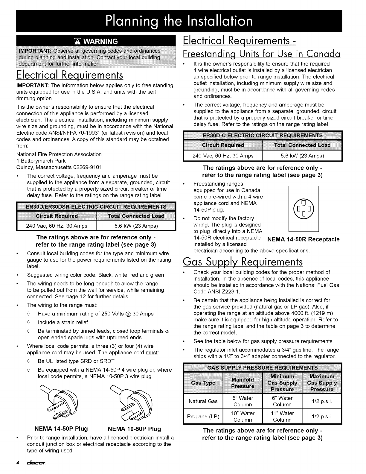
0 Be equipped with a NEMA 14-50P 4 wire plug or, where
local code permits, a NEMA 10-50P 3 wire plug.
NEMA 14-50P Plug NEMA 10-50P Plug
Prior to range installation, have a licensed electrician install a
conduit junction box or electrical receptacle according to the
type of wiring used.
Electrical Retirements -
Freestanding Units for Use in Canada
• It Jsthe owner's responsibility to ensure that the required
4 wire electrical outlet Jsinstalled by a licensed electrician
as specified below prior to range installation. The electrical
outlet installation, including minimum supply wire size and
grounding, must be Jnaccordance with all governing codes
and ordinances.
The correct voltage, frequency and amperage must be
supplied to the appliance from a separate, grounded, circuit
that is protected by a properly sized circuit breaker or time
delay fuse. Refer to the ratings on the range rating label.
240 Vac, 60 Hz, 30 Amps 5.6 kW (23 Amps) I
The ratings above are for reference only -
refer to the range rating label (see page 3)
• Freestanding ranges
equipped for use in Canada
come pre-wired with a 4 wire
appliance cord and NEMA /f E] -"_
14-50P plug. ttgJ
Do not modify the factory
wiring. The plug is designed
to plug directly into a NEMA
14-50R electrical receptacle NEMA 14-50R Receptacle
installed by a licensed
electrician according to the above specifications.
Gas Su J_,w uirements
• Check your local building codes for the proper method of
installation. In the absence of local codes, this appliance
should be installed in accordance with the National Fuel Gas
Code ANSI Z223.1.
Be certain that the appliance being installed is correct for
the gas service provided (natural gas or LP gas). Also, if
operating the range at an altitude above 4000 ft. (1219 m)
make sure it is equipped for high altitude operation. Refer to
the range rating label and the table on page 3 to determine
the correct model.
• See the table below for gas supply pressure requirements.
• The regulator inlet accommodates a 314" gas line. The range
ships with a 112"to 314" adapter connected to the regulator.
iiiiiiiiiiiiii i' i ! !i i i ii i! i ;!i i ili i i ili,!ii!a777777777iilIi ! 7
5" Water 6" Water
Natural Gas Column Column 1/2 p.s.i.
10" Water 11" Water
Propane (LP) Column Column 1/2 p.s.i.
The ratings above are for reference only -
refer to the range rating label (see page 3)
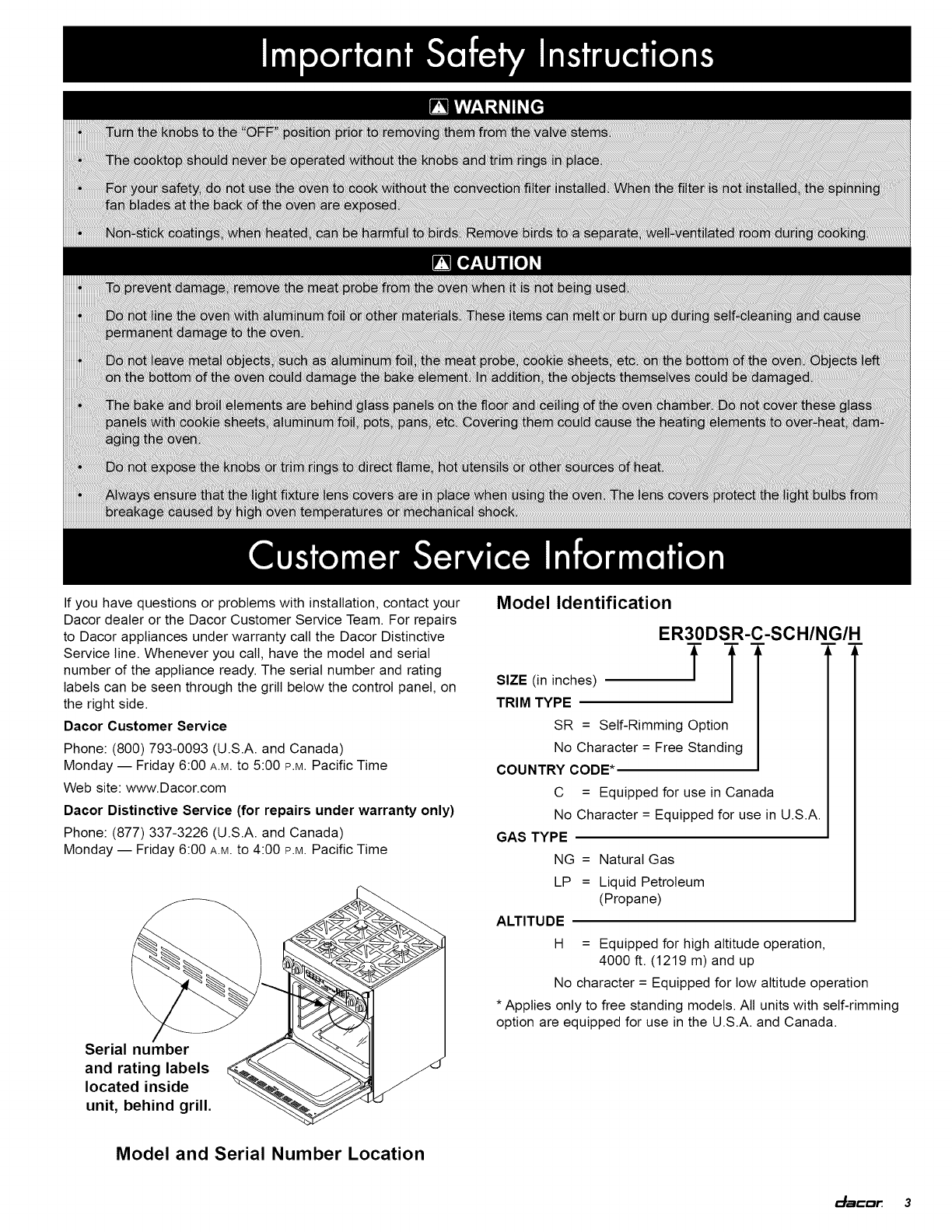
4_acar