Dacor Built-In Dishwasher User manual

Service Manual
Built-In Dishwasher

Table of ConTenTs
Section 1 - Safe Servicing Practices............................. 1-1
Section 2 - Operation ...................................................2-1
Static Fill..............................................................................2-1
Dynamic Fill.........................................................................2-1
Wash System.......................................................................2-2
Soil Sensing........................................................................2-2
Main Wash/Temp Assure....................................................2-3
Temperature Controls.........................................................2-3
Rinse Phases .....................................................................2-4
Condensate Drying.............................................................2-4
Section 3 - Cycle, Systems & Components ...............3-1
Dishwasher Control............................................................3-1
Auto Wash.........................................................................3-1
Heavy Wash......................................................................3-1
Normal Wash ...................................................................3-1
Short Wash........................................................................3-1
Rinse Hold.........................................................................3-1
Component Function Test .................................................3-1
Water/Service Test............................................................3-1
Entering the Water/Service Test........................................3-2
Water Temperature Test Mode..........................................3-2
Soil Sensor Test Mode......................................................3-3
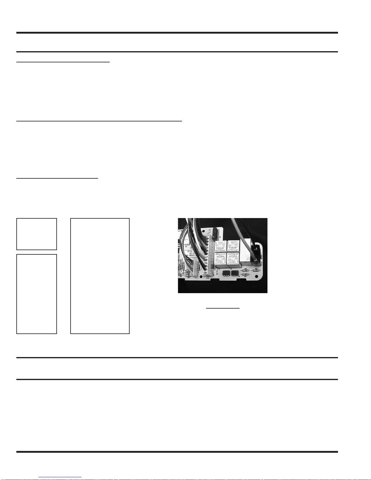
Electronic Control and Keypad Assembly.........................3-3
Control Board Plugs..........................................................3-3
Fill System...........................................................................3-3
Inlet Water Valve .................................................................3-3
To Check Inlet Water Valve...............................................3-4
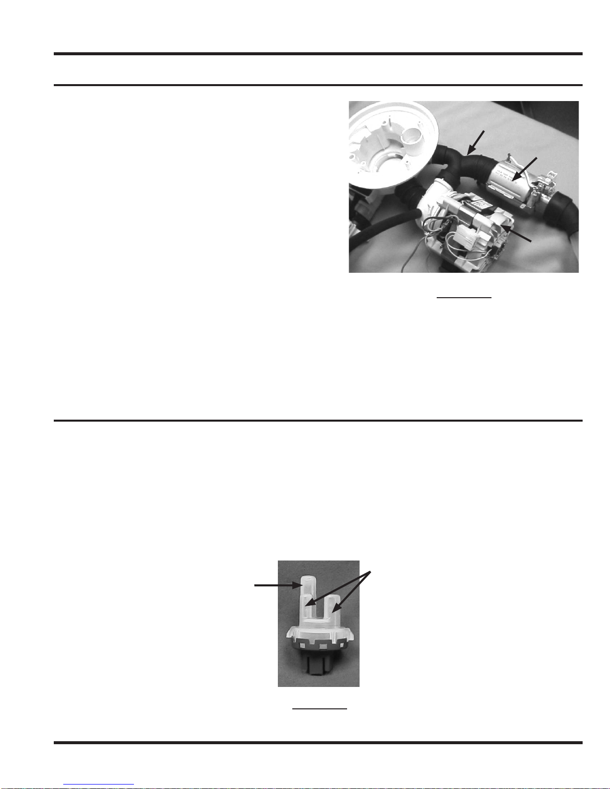
Pressure Switch Assembly................................................3-4
Low Water Level Switch.....................................................3-4
Checking Low Water Level Switch....................................3-5
High Water Level Switch....................................................3-5
Checking High Water Level Switch...................................3-6
Wash Motor .........................................................................3-6
Checking the Wash Motor.................................................3-6
Checking the Tachometer .................................................3-6
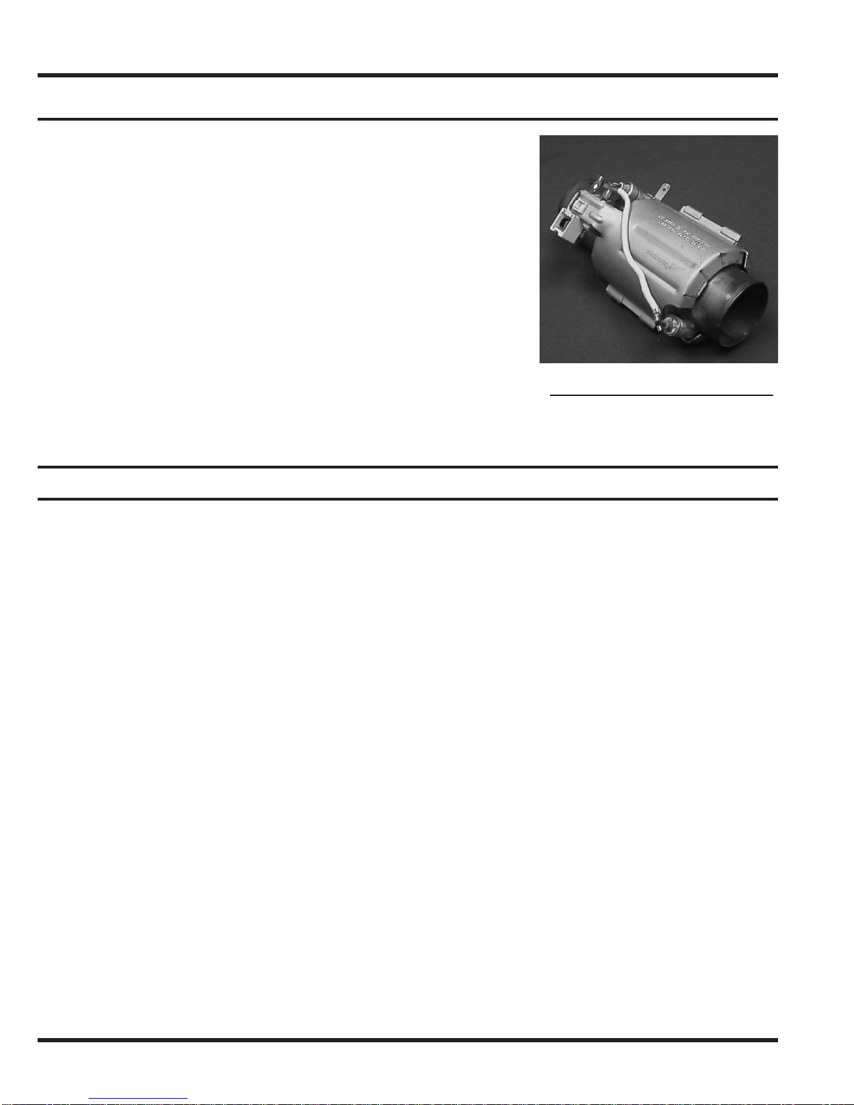
Heater...................................................................................3-7
Temperature Sensor and Soil Sensor...............................3-7
Checking the Thermistor...................................................3-7
Checking the Soil Sensor..................................................3-8
Drain Pump..........................................................................3-8
Checking the Drain Pump.................................................3-8
Dispenser.............................................................................3-9
Checking the Dispenser....................................................3-9
Fan Dry Unit ......................................................................3-10
Checking Fan Dry Motor.................................................3-10
Section 4 - Service & Disassembly.............................4-1
Safety Precautions .............................................................4-1
Door Panel...........................................................................4-1
Control.................................................................................4-1
Dispenser.............................................................................4-2
Lower Access Panel...........................................................4-2
Door Latch/Door Switch.....................................................4-2
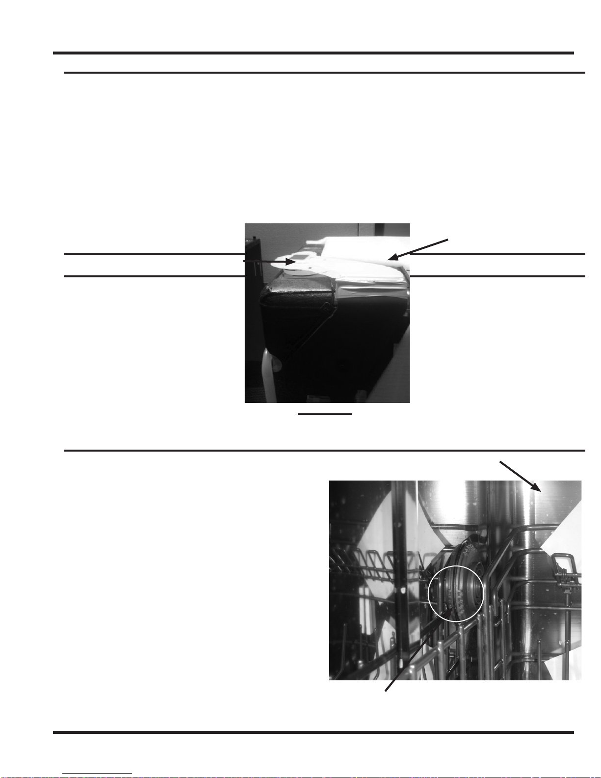
Upper Spray Arm ................................................................4-3
Lower Spray Arm................................................................4-3
Center Spray Arm and Upper Rack Manifold...................4-4
Main Delivery Tube.............................................................4-4
Upper Spray Arm Mount ....................................................4-5
Bottom Door Seal ...............................................................4-5
Door Seal.............................................................................4-5
Water Valve..........................................................................4-6
Cabinet Removal.................................................................4-6
Door Spring.........................................................................4-7
Hinge “C” Arm ....................................................................4-7
Door Seal Retainer..............................................................4-8
Pressure Switch Assembly................................................4-8
Thermistor/Soil Sensor......................................................4-9
Inline Heater .......................................................................4-9
Drain Pump........................................................................4-10
Wash Motor .......................................................................4-10
Capacitor ...........................................................................4-11
Blower Assembly..............................................................4-12
Sump..................................................................................4-12
Side Vent and Fill Hose....................................................4-13
Section 5 - Troubleshooting Tips................................5-1
Section 6 - Parts Breakdown.......................................6-1
Section 7 - Electrical Diagram.....................................7-1

Page 1-1
seCTion 1 - safe serviCing PraCTiCes
To avoid personal injury and/or property damage, it is important that Safe Servicing Practices be
observed. The following are some limited examples of safe practices:
DO NOT attempt a product repair if you have any doubts as to your ability to complete it in a safe
and satisfactory manner.
Before servicing or moving an appliance:
• Remove the power to unit.
• Turn off the gas supply.
• Turn off the water supply.
3. Never interfere with the proper operation of any safety device.
4. USE ONLY REPLACEMENT PARTS CATALOGED FOR THIS APPLIANCE. SUBSTITUTIONS MAY
DEFEAT COMPLIANCE WITH SAFETY STANDARDS SET FOR HOME APPLIANCES.
5. GROUNDING: The standard color coding for safety ground wires is GREEN, or GREEN with
YELLOW STRIPES. Ground leads are not to be used as current carrying conductors. It is
EXTREMELY important that the service technician reestablish all safety grounds prior to completion
of service. Failure to do so will create a hazard.
6. Prior to returning the product to service, ensure that:
• All electrical connections are correct and secure
• All electrical leads are properly dressed and secured away from sharp edges, high-temperature
components, and moving parts
• All non-insulated electrical terminals, connectors, heaters, etc. are adequately spaced away from
all metal parts and panels
• All safety grounds (both internal and external) are correctly and securely connected
• All panels are properly and securely reassembled
ATTENTION
This service manual is intended for use by persons having electrical and mechanical training and a
level of knowledge of these subjects generally considered acceptable in the appliance repair trade.
Dacor cannot be responsible, nor assume any liability, for injury or damage of any kind arising from
the use of this manual.
1.
2.
Section 1 - Safe Servicing Practices

Page 2-1
DaCor builT-inDishwasher serviCe Manual
In order to address service issues with the Dacor Built-In Dishwasher, the primary elements
of its operation are described below, as well as its physical components.
Static Fill
The cycle begins by activating the drain pump, ensuring the sump is empty. Operation then proceeds to
the fill stage where the fill valve regulates inlet water to 1.08 GPM between 20 and 120 psi. A fill hose
is attached to the fill valve and clamped to the bottom of an air gap mounted on the left hand side of
the tub. (The air gap prevents the siphoning of wash water back into the water supply system should
the water pressure drop to less then atmospheric pressure.) The inlet water enters the tub through
the vent opening on the left sidewall of the tub. As the fill continues, both the time of the fill and the
amount of water in the sump are monitored by the electronic control.
The pressure switch assembly mounted to the right side front frame has two pressure switches; a low
water level and a high water level switch. The contact in the low water level switch is open until the
water reaches the proper level in the sump. At this point, the switch closes (neutral to P3-9), starting
the Dynamic Fill.
Dynamic Fill
The closed circuit from the pressure switch starts the wash motor. The wash motor gains speed at the
rate of 100 RPM/second until full speed is attained. The water level inside the sump falls as the wash
motor gains speed. This opens the circuit on the low level pressure switch, allowing the water valve to
introduce more water to the tub. Once the wash motor reaches full speed, the inlet water continues to
fill until the low level pressure switch is reactivated (neutral to P3-9). This completes the fill phase of
the cycle.
PRESSURE SWITCH ASSEMBLY – FIGURE 1
Section 2 - Operation
Low Water Level Switch
High Water Level Switch

Page 2-2
seCTion 2 - oPeraTion
Wash System
Once filling is complete, the dishwasher enters the
pre-wash phase. The pre-wash phase conditions the
soil with water and detergent to prepare it for removal
in the main wash phase.
Once water enters the tub, the pump draws the water
into the sump through a primary filter at the bottom
of the tub to prevent food from circulating through the
wash system and redepositing on the dishes. In the
center of the primary filter is the lower spray arm and
drain filter assembly. The drain cap, snapped into the
drain cup, prevents food particles from entering the
drain section of the sump.
As the wash water flows through the filters, soil levels
and water temperatures (see Soil Sensing section, this
page) are measured by the Soil Sensor/Thermistor
assembly. The wash motor discharges the wash water
through two ports, feeding the lower, center, and
upper spray arms. The larger of the ports feeds water
through a “Y” hose to separate the lower and center
spray arm wash water. The water flowing to the center
spray arm first passes through an inline water heater
before entering the delivery tube. The water flowing to
the lower spray arm passes through the sump on its
way to the lower spray arm.
Soil Sensing
Soil sensing is performed in all wash cycles except the Rinse Only cycle. Mounted on the right side of
the sump, the soil sensor transmits light from a transmitter to a receiver to measure the amount of soil
in the water. This information will be used by the control to determine the length of the cycle.
Once pre-wash loosens food on the dishes, the motor stops for 30 seconds. This allows the wash water
and food soils to settle for the soil sensor to check the soil levels in the water.
Now that this reading is taken, the dishwasher drains the dirty water and fills again for the pre-wash
rinse. Once this rinse is complete, the wash motor pauses again, a soil level measurement is again
taken. The control uses these readings to adjust the wash cycle to ensure a clean load of dishes.
FIGURE 3
FIGURE 2
Sump
“Y” Hose
Inline Heater
Wash
Motor
Thermistor Soil Sensor

Page 2-3
DaCor builT-inDishwasher serviCe Manual
Main Wash/Temp Assure
After the final reading by the soil sensor, the unit drains before
starting to fill for the main wash. The tub fills, with the wash
motor starting after the low level pressure switch is activated.
The detergent dispenser now opens, introducing detergent
into the wash cycle. The electronic control checks the water
temperature through the thermistor, energizing the inline heater
to maintain or heat the wash water entering the second level
spray arm.
The main wash temperature has been predetermined for the
wash cycle selected. At this point, depending on the required
temperature (Temp Assure), the electronic control pauses the
time remaining to allow the wash water to heat to the desired
setting. If Temp Assure is not reached, the dishwasher pauses
time between 0 and 10 minutes to allow the temperature to
increase during several periods of the main wash. Once the main
wash cycle is completed, the dishwasher goes through the drain
phase before filling for the rinse phase of the cycle.
Temperature Controls
Options allow the consumer the choice to control the temperature at which the main wash operates.
The main wash water can be heated to increase the performance of the chosen wash cycle.
If the High Temp option is chosen, the required temperature (Temp Assure) during the main
wash is increased to 140°F. The control will pause the time remaining for up to 10 minutes
to allow the water to heat to this temperature. Whether or not the water temperature
reaches this in 10 minutes, the cycle continues without indication that it reached or did not
reach this temperature.
When the Sanitize option is chosen, the National Sanitation Foundation requires, in the final rinse cycle,
that 155°F be reached and maintained for a certain amount of time. During the final rinse, the control
pauses the time remaining for up to 30 minutes to reach Temp Assure (155°F for Sanitize) before
proceeding to the end of the cycle. Should the cycle meet the requirements defined by the Sanitize
option, the Sanitize ring will remain lit following the completion of the cycle. The ring will not light if
Temp Assure is not met.
INLINE HEATER – FIGURE 4

Rinse Phases
The first rinse phase follows the pre-wash portion of a wash cycle. During this rinse phase, the motor
ramps up by 100RPM/second to full speed (2800RPM). Once at full speed, however, the motor will cycle
between 1600RPM and 2800 RPM throughout the rest of this rinse phase. This motor action aids in the
removal of food from the dishes so it can be filtered from the water.
The final rinse phase begins, following the end of the main wash. Rinse agent is added to the
water during the final rinse. Rinse agent speeds drying, removes water spots, and water streaks
from glassware.
If the Sanitize option has been chosen, the control will pause the time remaining to allow the heater to
increase the water temperature to 155°F. This delay will last up to 30 minutes before resuming the rest
of the cycle. The Sanitize outer ring will light following the wash only if 155°F is achieved.
FIGURE 5
Condensate Drying
This dishwasher is designed and equipped with a
condensate drying system. Steam is drawn from the
tub by the condensate fan and forced through the
condensate duct. As it flows through the condensate
duct, the cool surface of the baffles condenses the
steam into water allowing the now cooler and drier
air to exit into the tub through the condensate vent.
The condensate vent is also the exit for the water
from the condensate duct into the
tub to be drained.
This circulation starts before the unit has completed
draining and continues for the rest of the drying
phase of the wash cycle. The air intake and
condensate vent are shown in Figure 6.
The final operation of the wash cycle energizes the
fill valve long enough to allow the soil sensor to
recalibrate itself with fresh, clean water.
Page 2-4
seCTion 2 - oPeraTion
Blower Fan
Air Duct
Intake
Side Vent
Air Return

Knowledge of the dishwasher’s cycles and systems is necessary in diagnosing any potential
operational problems. Methods for diagnosing these problems, such as taking resistance
readings and testing for closed circuits are outlined in the following section as well.
Dishwasher Control
All of the functions and operations of this dishwasher are dictated and monitored by the electronic
control. The control maintains the proper water temperature in the wash and rinse cycles to ensure
proper cleaning for the wash cycle selected. (This temperature may not be the same for all cycles.)
The control also monitors the soil concentration in the water with the use of a turbidity sensor mounted
in the sump.
Auto Wash
This cycle factors in the size of the load, the amount of soil on the dishes, and the temperature of the
water to create an appropriate cycle for each load. Auto wash uses water temperature to determine
the length of the wash cycle. Water temperature is monitored to assess the rate at which the water
temperature decreases. A rapid decrease in temperature alerts the control to extend the wash time.
(Larger loads have higher rates of temperature decrease, therefore longer wash cycles.)
As the water is assessed for temperature changes, it is also adjusted to maintain proper temperature
throughout the cycle. The control also checks the soil concentration in the water to determine the
number of rinses needed for cleaning.
Heavy Wash
This cycle is intended for heavy soil levels. The water temperatures for both wash and rinse cycles are
automatically selected. It includes a high temperature wash and sanitize rinse. Soil sensing is used in
this cycle.
Normal Wash
This cycle is intended for normal soil level. All options (high temperature wash, sanitize rinse, and delay
start) are available at the user’s discretion. Soil sensing is used in this cycle.
Short Wash
This cycle is intended for light soil levels. All options (high temperature wash, sanitize rinse, and delay
start) are available at the user’s discretion. Soil sensing is used in this cycle.
Rinse Hold
This cycle is intended for dishes that are to be washed later. It is a rinse-only cycle; options and soil
sensing are not available.
Component Function Test
Water/Service Test
The service test will check the electronic control’s ability to run all functions of the dishwasher.
This test may be entered from an idle mode or the power failure mode, however different pads
are used to activate.
Section 3 - Cycle, Systems & Components
Page 3-1
DaCor builT-inDishwasher serviCe Manual

Page 3-2
seCTion 3 - CyCle, sysTeMs & CoMPonenTs
Component Function Test (continued)
Entering the Water/Service Test
From Power Failure
While the control displays power failure or flashing lights, press and hold the Short wash and the Rinse
& Hold pads simultaneously for one second. The dishwasher will start through the test cycle.
From Idle
With no cycle selected and the dishwasher sitting idle, press and hold the Hi-temp and the Start pads
simultaneously for one second. The dishwasher will start through the test cycle.
The chart below shows the complete Water/Service Test cycle. To manually move to the next phase
of the cycle press the Start pad. If at any time the door is opened the test cycle will end and flashing
lights will come on showing power failure. The Sanitize LED will light at the end of test to check the
LED. If the rinse aid dispenser is empty, the display will read LO to indicate the contact in the dispenser
is closed.
Water Temperature Test Mode
This test is for testing the thermistor in the sump as well as the control.
Start a Normal wash cycle and allow the dishwasher to fill and wash for two minutes at which time,
press the Start/Cancel pad twice (2). This will stop the dishwasher and send it to idle.
With the dishwasher in idle press and hold the Normal wash and the Start/Cancel pads
simultaneously will start the test. The test will show a two digit display for the temperature of the
water (from 0°F to 99°F). If the water temperature is over 99°F a decimal point will be displayed
to show 100°F, then the added degrees over. This reading will be updated every three seconds until
the Start/Cancel pad is depressed to stop the test.
1.
2.
Step
Description
Time
Water Valve
Wash Motor
Drain Pump
Heater
Dispenser
Fan
Sensing LED
Drying LED
Sanitized LED
Dispenser Low LED
Clean LED
1 Fill / Dispenser
3 Wash / Heat
4 Pause
5 Wash / Heat
6 Wash / Heat / Dispenser
7 Drain
Completion
* Dynamic fill - water valve is open until pressure switch is closed
2 Fill / Dispenser / Wash
8 Dry
59 1 0 0 0 0 0 1 0 0 0 0
21 1 0 0 1 0 1 0 0 0 0
*
45 0 1 0 1 0 0 1 0 0 0 0
0.6 0 0 0 0 0 1 0 0 0 0 0
75 0 1 0 1 0 0 0 0 0 0 0
80 0 1 0 1 1 0 0 0 0 0 0
90 0 0 1 0 0 0 0 0 0 0 0
90 0 0 0 1 0 1 0 1 0 0 0
460.6 1 0/1 1

Component Function Test (continued)
Soil Sensor Test Mode
This tests the sensor for proper operation as well as the value that the sensor is detecting.
To activate the test you must press and hold the Heavy and Start pads simultaneously.
When the test mode is activated, the digit display will show the turbidity value of the sensor.
This display will be a voltage reading in the decimal value.
To terminate this test press the Start pad.
Electronic Control and Keypad Assembly
The control on the dishwasher consists of the control board and the switch assembly. The switch is
installed into the top of the outer door panel, an elastomer keypad, used to actuate the switch, is
inserted into holes in the top of the outer door panel. The keypad assembly is attached to the control
board with a connecting ribbon. The keypad is held in place by a spacer that is clipped to the top of the
mount holding the control board. The control is mounted to a carrier panel that is attached to the outer
door panel. It is covered with a mylar blanket.
Control Board Plugs
Throughout this section references are made to the plug and pin location on the electronic control.
Figure 7 shows a picture of the electronic control pointing out plug numbers as well as pin and color of
the wire in each location.
Fill System
Two major components in the fill system are the inlet water valve and the pressure switch assembly.
Inlet Water Valve
The inlet valve is an electrically controlled shut-off valve that is used to allow water to enter the
dishwasher. The valve has a flow restrictor to regulate the water flow to 1.08 GPM at between 20 and
120 psi into the tub. The inlet valve is wired to the electronic control and is opened and closed by the
control. The inlet water valve is located on the front left frame leg just behind the lower front panel.
1.
2.
3.
FIGURE 7
Page 3-3
DaCor builT-inDishwasher serviCe Manual
Plug #1
#1 Black
#8 Gray
Plug #2
Black 1
Red 2
Purple 3
Brown 5
Orange 6
White 7
Plug #3
1 White
2 Brown
3 Blue
4 Black
5 Yellow
6 Brown
7 Black
8 White
9 Orange
10 Blue
11 Red

Inlet Water Valve (continued)
To Check Inlet Water Valve
Disconnect dishwasher from power supply.
To access electrical connections to valve, remove lower front panel.
Using ohmmeter, check between P3-5 (yellow wire) and P3-8
(white wire). The resistance reading of the solenoid coil should
be 1126 ohms.
Pressure Switch Assembly
The pressure switch assembly consists of a low water level switch and a high water level switch with
common bracket. This assembly is mounted to the right side frame behind the junction box.
Low Water Level Switch
The low water level switch is used to maintain the water level in the sump for the fill cycle. The
switch has a hose connecting it to the sump. As the water level in the sump rises, air in the hose is
compressed and forced against the diaphragm in the switch. This compressed air causes the contact in
the switch to close. When the switch closes the first time, it starts the wash motor.
1.
2.
3.
Page 3-4
seCTion 3 - CyCle, sysTeMs & CoMPonenTs
FIGURE 8
FIGURE 9
Low Pressure Switch
High Pressure
Switch

Low Water Level Switch (continued)
Checking Low Water Level Switch
Disconnect power to dishwasher.
Gain access to electronic control and check between P3-9 (orange wire) and P3-8 (white wire).
This should be an open contact.
These wires are connected to center terminal #1 and terminal to the right of center #3.
Add water to sump to close switch. (See Figure 10)
High Water Level Switch
The high water level switch is a back up, or safety, for the low water level switch. The high water level
switch is placed in series with the drain pump. If the low water level switch fails to close, the drain
pump starts automatically. The high water level switch is an open switch. It is connected to the sump
by a separate hose.
1.
2.
3.
4.
FIGURE 10
Low Water Level
Switch will close at
this level
FIGURE 11
Low Water LevelHigh Water Level
Check between
these two terminals
Check between
these two terminals
Page 3-5
DaCor builT-inDishwasher serviCe Manual

High Water Level Switch (continued)
Checking High Water Level Switch
Checking continuity through the high water level switch is easier at the control.
Disconnect power to dishwasher.
Gain access to electronic control and check for continuity between the L1 black wire and P3-6
(brown wire). This contact should be open.
These wires are connected to center terminal #1 and terminal to the right of center #3 on
the switch.
This contact will close when water inside the tub reaches the rails for the lower wash rack.
Wash Motor
The wash motor, mounted to left side of the sump, is connected
to it by two separate hoses. The permanent split capacitor motor
operates on 120 VAC, 1.8 amp 60 Hz.
The motor speed varies as needed for different wash cycles. The
speed varies by changes made to the voltage sine wave, as power
is applied to the motor. At full speed the wash motor runs at
approximately 2800 RPM.
The motor speed varies at the beginning of the wash cycle as the
tub fills with water. After the wash motor starts at 310 RPM, it
increases speed at a rate of 100 RPM/second until full speed is
reached. The motor speed also varies during Pulse Wash, where
the motor speed is changed from 1600 RPM to 2800 RPM to aid in
cleaning the filter, while reducing noise.
The electronic control monitors the speed of the motor through
the tachometer mounted on the rear of the motor. (See Figure
13) The tachometer is an AC generator, which provides feedback
information to the control for regulating the motor speed.
Checking the Wash Motor
Disconnect dishwasher from power supply.
Due to the location of the motor disconnect plug, resistance
readings should be made at the control.
• Remove outer door panel to gain access to the control.
• The run windings for the motor are connected between
P3-1 and P3-4.
The resistance should read 14 ohms.
Checking the Tachometer
Disconnect dishwasher from power supply.
Due to the location of the motor disconnect plug, resistance
readings should be made at the control.
• Remove outer door panel to gain access to the control.
• The tachometer leads are between P3-10 and P3-11.
• The resistance should read 246 ohms.
1.
2.
3.
4.
5.
1.
2.
3.
1.
2.
Page 3-6
seCTion 3 - CyCle, sysTeMs & CoMPonenTs
WASH MOTOR – FIGURE 12
FIGURE 13
Tachometer mounted on the rear
of the motor

Page 3-7
DaCor builT-inDishwasher serviCe Manual
Heater
The heater in this dishwasher is inline between the wash
motor and the delivery tube. The 1200W heater wraps around
a stainless steel core tube. The heater can only be energized,
during a wash cycle, while the wash pump is running after the
low level pressure switch has been activated. Water is heated
as it passes through the heater to the center spray arm. This
heater has internal thermal protection.
While checking the heater, do not apply power to
it until the tub has filled with water and the motor
is operating!
Temperature Sensor and Soil Sensor
The electronic control reads information from two sensors to
adjust the wash cycle. The Thermistor and soil sensor are
integrated into the same housing mounted to the right side of
the sump. Both sensors extend into the outer section of the
sump to perform independent tasks.
The electronic control uses the Thermistor to monitor the
temperature of the water in the dishwasher. The turbidity or
soil sensor is used to monitor soil levels during a wash cycle.
A small amount of DC power is sent to the soil sensor emitter
mounted in one of the posts of the sensor housing. This emitter
turns DC power into a small beam of light to be transmitted to a
detector in the other post. As this light passes from one post to
another, the amount of soil in the water partially blocks the light
seen by the detector. The detector changes this light back into
DC voltage which returns to the control for analysis.
The level of soil in the water can be determined by this
returned voltage. Based on this information, the control makes
adjustments to the remainder of the wash cycle.
Checking the Thermistor
Start a Normal wash cycle and allow the dishwasher to fill and
wash for two minutes at which time press the Start/Cancel pad
twice (2). This will stop the dishwasher and send it to idle.
With the dishwasher in idle, press and hold the Normal wash and
the Start/Cancel pads simultaneously to start the test. The test
will show a two digit display for the temperature of the water
(from 0°F to 99°F). If the water temperature is over 99°F a
decimal point will be displayed to show 100°F, then the added
degrees over. This reading will be updated every three seconds
until the Start/Cancel pad is depressed to stop the test.
Refer to Water Temperature Test Mode on page 3-2 to check
the temperature of the thermistor.
1.
2.
INLINE HEATER – FIGURE 14
SENSOR MOUNTED
INTO SUMP – FIGURE 15
Thermistor
SENSOR WITH SEAL
– FIGURE 16
Thermistor Turbidity Sensor

Page 3-8
seCTion 3 - CyCle, sysTeMs & CoMPonenTs
Checking the Soil Sensor
While in idle mode, simultaneously press and hold Heavy Wash and Start/Cancel buttons.
• This activates the sensor value test.
• If a number does not display, continue with the test.
Disconnect dishwasher from power supply.
Check soil sensor circuit at control.
• A resistance reading should be taken between P2-1 black and P2-7 white at the control for
the emitter.
• A resistance reading should be taken between P2-2 red and P2-7 white at the control for
the detector.
Drain Pump
This dishwasher contains an independent drain pump. It is of a wet rotor design to prevent leaks. The
drain pump is mounted directly to the rear of the sump. The pump cover can be removed for cleaning.
The discharge end of the pump has a check valve to prevent water and odors from entering the
dishwasher from the house drain system. The intake of the pump is connected to the sump by a short
connecting hose. The pump is delivered as a complete assembly.
Checking the Drain Pump
A service test can be performed to test all functions of the dishwasher, including the drain pump.
• The service test is covered in section “Component Function Test”.
IF THE DRAIN PUMP DOES NOT OPERATE
Disconnect dishwasher from power supply.
The location of the drain pump requires that you check the circuit at the control.
• Check between P3-6 brown and P3-8 white.
The resistance should read 26 ohms.
1.
2.
3.
1.
2.
3.
DRAIN PUMP – FIGURE 17
Check Valve Mounting Tab

Page 3-9
DaCor builT-inDishwasher serviCe Manual
Dispenser
The dispenser consists of two dispensers in one housing, controlled by the use of one wax motor
actuator. The first time the actuator is energized in the cycle, detergent is dispensed. The second time
the actuator is energized, rinse agent is dispensed.
The rinse aid half of the dispenser can be adjusted to meet the customer’s needs. This is done by
removing the cap from the dispenser and adjusting the arrow inside to a higher number. The higher
the number, the more agent is dispensed during the rinse cycle. A sensor inside the rinse aid reservoir
triggers the control to display “LO” when the level of rinse agent is low. The “LO” display on the control
will not affect the operation of the dishwasher.
Checking the Dispenser
An operational check of the dispenser can be done using the
Component Function Test.
• The service test is covered in section “Componenet Function Test”.
IF THE DISPENSER DOES NOT OPEN
Disconnect dishwasher from power supply.
Remove outer door panel.
• The wax motor normal resistance is 1665.
3. Check rinse agent indicator switch.
• An empty dispenser will have a resistance reading
of 0 ohms.
• A dispenser with rinse agent will have an open
resistance reading.
1.
2.
FIGURE 18
Contacts for Rinse
Aid Level Switch
FIGURE 19
Arrow Adjustment for Rinse Aid
Wax Motor Actuator

Page 3-10
seCTion 3 - CyCle, sysTeMs & CoMPonenTs
Fan Dry Unit
Dishes are dried with a fan driven condensate system. This system is made up of
(refer to Figures 20, 21):
Fan Dry Motor
Air Intake
Condensate Duct
Condensate Vent
As the dishwasher completes its final drain, the fan dry motor forces saturated air across cool baffles
in the condensate duct, resulting in the removal of moisture from the air. The cooler, drier air and
condensed water are returned to the tub through the condensate vent. The drying process continues
until moisture is removed from the air left in the tub, thus allowing the hot dishes to completely dry.
Checking Fan Dry Motor
Disconnect dishwasher from power supply.
Fan dry motor can be checked at the control panel between P3-3 blue and P3-8 white.
• Normal resistance is 2088 ohms.
1.
2.
3.
4.
1.
2.
FIGURE 20
Air Intake Fan Dry Motor
FIGURE 21
Condensate Duct
Condensate Vent
Inlet Water Connection

Page 4-1
DaCor builT-inDishwasher serviCe Manual
Safety Precautions
Always turn off the electric power supply before servicing electrical components, testing with an
ohmmeter, or replacing parts. Refer to Safe Servicing Procedures at the front of this manual before
servicing the dishwasher.
All voltage checks should be made with a voltmeter having a full scale range of 130 volts or higher.
After service is completed, be sure all safety-grounding circuits are complete, all electrical connections
are secure, and all access panels are in place.
If the repair on this product requires the removal of door panel, liner, or the cabinet, you may find
exposed sharp edges. Removing the door could expose sharp edges - use extreme caution.
Care must be taken to avoid injury while working with exposed sharp edges. It is highly recommended
that protective clothing and gloves are worn while performing service to this product.
Door Panel
In order to access the electronic controls, the outer door panel
must be removed from the door assembly.
Disconnect dishwasher from power supply.
The outer door panel is mounted to the inner door panel by
Phillips head screws (Figure 22).
Removing the outer door panel will expose sharp edges on
the inner door panel.
Be sure to support outer door as screws are removed to
prevent damage to outer panel and dishwasher.
Remove wiring harness from control and ground connection
on door panel.
The outer door panel is disconnected.
Control
Disconnect dishwasher from power supply.
Remove outer door panel (see Service and Disassembly
section labeled Door Panel).
Lay outer door panel face down on a protective surface.
Compress plastic retainers with a pair of pliers to release
the electronic control from carrier panel (Figure 23).
Lift control from mount.
With the control removed, pull protective shield back to
free ribbon from keypad assembly.
Remove two screws holding outer door reinforcement to
outer door panel.
These screws also hold the door handle in place.
Do not drop door handle.
Remove this reinforcement to gain access to keypad assembly.
To install parts, reverse procedure.
1.
2.
3.
4.
5.
6.
1.
2.
3.
4.
5.
6.
7.
8.
9.
10.
11.
Section 4 - Service & Disassembly
FIGURE 22
PLIERS ON MOUNT – FIGURE 23

Page 4-2
seCTion 4 - serviCe & DisasseMbly
Dispenser
Disconnect dishwasher from power supply.
Remove outer door panel (see previous section for
detailed instructions).
Remove six screws securing dispenser assembly to
inner door panel. Retainer brackets on the top and
bottom may also need to be removed.
Lower Access Panel
Remove bottom kick plate.
Remove screws on each side of lower access panel.
(See Figure 25)
Remove access panel.
EDGES ARE SHARP - USE EXTREME CAUTION
Door Latch/Door Switch
Remove outer door panel. (See previous section for detailed instructions.)
Remove two screws mounting the latch/switch assembly to inner door panel, and then
remove two wires.
Reinstall wires to door latch/switch assembly and remount assembly to inner door panel.
Close door to make sure strike catches latch cam to close door switch.
If door strike needs to be adjusted, loosen retaining screw in top of tub. This allows strike
to be moved as needed. Tighten retaining screw after adjustment is made.
1.
2.
3.
1.
2.
3.
1.
2.
3.
4.
5.
FIGURE 24
FIGURE 25
Remove these screws
FIGURE 26 FIGURE 27
Latch cam in
open position

Page 4-3
DaCor builT-inDishwasher serviCe Manual
Upper Spray Arm
The center of the upper spray arm is a locking mount.
Turn upper spray arm and mount counterclockwise to remove. (See Figure 28)
To reinstall upper spray arm, line up locking posts in center mount with locking tabs on upper spray
arm support. Turn clockwise until it locks securely.
Lower Spray Arm
Remove lower rack.
Lower spray arm snaps onto volute cover.
Lift arm to remove.
1.
2.
3.
1.
2.
3.
FIGURE 28
Turn center of spray arm to remove
FIGURE 29
All 3 dishwasher spray arms
Table of contents
Other Dacor Dishwasher manuals

Dacor
Dacor DDWF24S User manual

Dacor
Dacor ED24 User manual

Dacor
Dacor EDWH24S Technical manual

Dacor
Dacor DDW24M999UM User manual

Dacor
Dacor DDWF24S Technical manual

Dacor
Dacor DDW24T99 Series User manual

Dacor
Dacor EDW24S User manual

Dacor
Dacor Epicure ED30 User manual

Dacor
Dacor DDWF24S Technical manual

Dacor
Dacor DDWF24S User manual

Dacor
Dacor DDW24S Technical manual

Dacor
Dacor Millennia EDW24 User manual

Dacor
Dacor RDW24 User manual

Dacor
Dacor DDW24S User manual

Dacor
Dacor EW User manual

Dacor
Dacor Millennia MDW24S Owner's manual

Dacor
Dacor RDW24 User manual

Dacor
Dacor EDW24S User manual

Dacor
Dacor DDW24S User manual

Dacor
Dacor ED24 User manual